Redland DuoPlain User manual

SOLAR PV TILES
Installation Instructions for Redland DuoPlain Solar PV Tiles
Version: 3
Date: July 2012
Author: Kevin Ley / Michael McHugh / Graham Faulkner
Department: Redland Technical Solutions / Marketing

Solar PV Tiles – Installation Instructions 18 July 2012
Page 1 of 13
TABLE OF CONTENTS
Table of Contents 1
1 INTRODUCTION 2
1.1 Health & Safety 2
1.2 Equipment Required 3
2 PRELIMINARIES 4
2.1 Circuit Diagram & Layout 4
2.2 Felt & Battens 5
2.3 Marking Position 5
2.4 Rafter Pitches & Lengths 5
2.5 Fixing 6
2.6 Installation 7
3 DUOPLAIN 8
4 CONNECTIONS TO INVERTER 11
5 REPLACING A PV LAMINATE 13

Solar PV Tiles – Installation Instructions 18 July 2012
Page 2 of 13
1 INTRODUCTION
It is highly recommended that you read all the guidance and
installation notes before starting the installation to ensure that the
Redland Solar PV tiles and system are installed safely.
1.1 HEALTH & SAFETY
1.1.1 GENERAL GUIDANCE
•Ensure most up to date Construction (Design and Management) Regulations (CDM) and
general construction site training are followed.
•Any person handling PV tiles should be trained in correct manual handling practice. Please
note also that PV tiles can have sharp edges and so appropriate safety gloves should be
worn when handling panels.
•All appropriate Health and Safety regulations should be followed correctly.
•Avoid installing the system in poor weather conditions, including strong wind, rain, ice or
snow.
•Do NOT walk on the PV tiles at any time.
•The slating and tiling should be carried out in accordance with the current version of British
Standard BS 5534, Code of practice for slating and tiling (including shingles) and current
Redland Solar PV tile fixing instructions.
•Install all components as specified within this guide to ensure weather-tightness and wind
uplift security.
1.1.2 ELECTRICAL HAZARDS
Photovoltaic (PV) tiles do not present a risk as long as appropriate safety practices are
followed at all times during installation. In particular, you must be aware of the following:
•PV tiles produce a DC voltage whenever exposed to light. This voltage cannot be switched
off.
•All work must be carried out with the system disconnected from the main electrical supply.
•PV tiles are pre-wired with insulated connectors to prevent an electrical shock during
general handling. However, care must be taken not to cut or damage PV tile cable
insulation or expose bare wire.
•Ensure all PV tile cable connectors are dry and free of dirt before making connections.
•Ensure no PV tile cable ends are left exposed to the weather during pauses in the work
schedule or after completion of the works.
1.1.3 INSTALLATION PREPARATION
Follow the guidance below to ensure the Redland PV tiles are installed and handled
correctly:
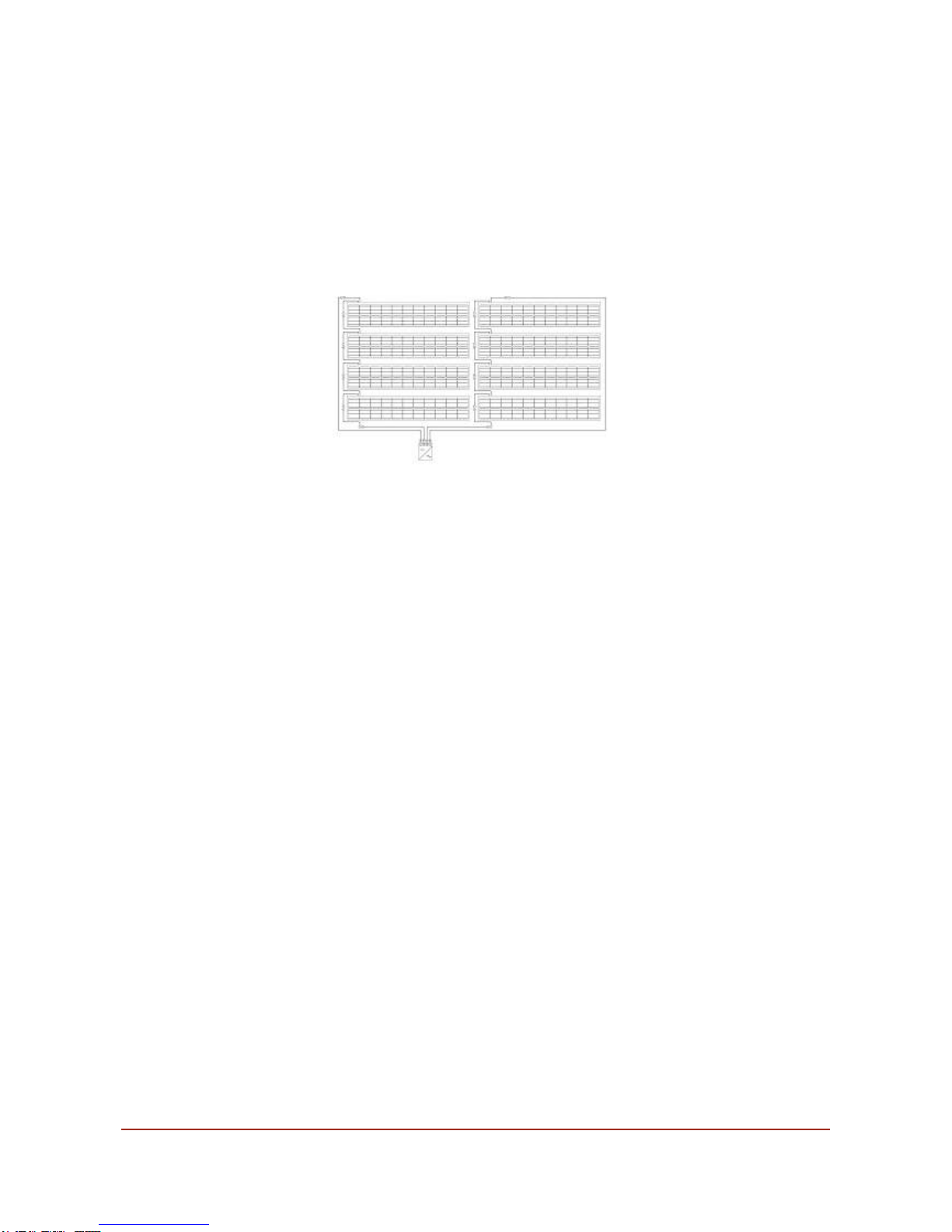
•Use this installation guide alongside your PV tile layout and circuit diagram to determine
the location and layout of the Redland Solar PV tiles and associated PV tile cables on the
roof.

Solar PV Tiles – Installation Instructions 18 July 2012
Page 3 of 13
•Keep the Redland PV tiles in a weatherproof environment prior to installation.
•Carry the Redland PV tiles with both hands by the frame, avoiding touching or scratching
the face of the panels.
•Only load as many Redland PV tiles onto the roof as you expect to install during the work
session.
•Secure or remove any uninstalled PV tiles before leaving the roof to avoid possible wind
damage or theft.
•Do not leave tools or unsecured materials above the Redland PV tile installation area, to
avoid potential damage to the PV tiles.
1.2 EQUIPMENT REQUIRED
•Screwdriver or hand-held power screwdriver with pozi-drive head.
•Voltmeter to check PV tile cable connections (Note: It is recommended to test the voltage
across every 4 connected PV tiles as the installation proceeds to check the integrity of the
PV tiles and their electrical connections).

Solar PV Tiles – Installation Instructions 18 July 2012
Page 4 of 13
2 PRELIMINARIES
2.1 CIRCUIT DIAGRAM & LAYOUT
Before starting please check the circuit diagram to confirm the required layout of the PV tile
array and the associated electrical connections between PV tiles and also back to the DC to
AC Inverter. Redland Solar PV tiles are connected in electrical series in strings with each
string having its own connections back to the inverter. The PV tile connectors and cables
provided must be used for the series connection of the PV tile columns. PV tiles come with
pre-wired connectors for tile-to-tile connections within a PV column. Additional PV tile cables
are available in two lengths – 2 m cables for tile-to-tile connections between columns and 10
m cables for tile-to-inverter connections. A circuit diagram showing the recommended cabling
plan (not to scale) for a single string array of 8 PV tiles is shown below.
For Redland Solar PV tiles, the recommended direction of cabling within a string is in column
fashion, from bottom to top, then top to bottom in adjacent column, and then bottom to top
again, and so on as you work across the PV array with the PV tile columns running from right
to left. The pre-wired connectors attached to the PV tiles should be used for all the electrical
connections up or down a column. 2 m cables should be used for connecting PV tile columns
to each other; connections between adjacent PV tile columns should be made top-to-top,
then bottom-to-bottom, then top-to-top, and so on as you work across the PV array. The 10 m
cables should be used to connect the first and last PV tiles in the string to the inverter. As a
rule of thumb, the 10m cables should be long enough for the connections to the inverter for
PV tile arrays up to 4 columns of PV tiles wide; for wider PV tile arrays it may be necessary
to use longer inverter cables. Monier Limited can also supply 25m inverter cables if required.
Note that for all electrical connections the pre-wired connectors and cables are used to
connect from the + terminal to the - terminal in electrical series.

Solar PV Tiles – Installation Instructions 18 July 2012
Page 5 of 13
Additional strings of PV tiles connected in electrical series can be connected to the inverter
using the other sets of + and – inputs available on the inverter box. Note the maximum
number of PV tiles that can be connected to the inverter is only limited by the capacity of the
inverter. Check that the inverter has sufficient capacity for the size of the array being
connected. For large projects more than one inverter may be required.
The circuit diagram below shows the recommended cabling plan (not to scale) for 2 strings of
4 PV tiles each connected to a single inverter.
2.2 FELT & BATTENS
Felt and batten the roof in the normal manner ensuring the roofing underlay is laid with an
approximate 10mm drape between rafters and that the tiling battens are laid at the
appropriate gauge for the PV tile type to be used (see relevant section to follow for the
specific PV tile being installed).
2.3 MARKING POSITION
To make sure the PV tile array is installed in the correct position of the roof, it is
recommended that you first mark out the area where the PV tiles are to go before you begin.
It is also recommended that the position of the inverter(s) within the building in relation to the
PV array is (are) identified.
2.4 RAFTER PITCHES & LENGTHS
For Cambrian Slate, Mini Stonewold, Mockbond Mini Stonewold, Landmark Double Pantile,
Grovebury, Landmark Double Roman, 50 Double Roman, DuoPlain, Richmond 10, Saxon 10,
Landmark Slate 10, MockBond Richmond 10, Natural Slate and Plain Tiles (including
Rosemary Clay Plain Tiles) follow the appropriate PV tile installation instructions in following
sections. The maximum rafter length for flat interlocking tiles and slates at minimum rafter
pitch is 10 m. (9 m for Natural Slate in moderate exposure areas, 6 m in severe). Please
contact Technical Solutions for further advice on rafter lengths. Note that the minimum and
maximum rafter pitch for use of each of the Redland Solar PV tiles is shown in the table
below:

Solar PV Tiles – Installation Instructions 18 July 2012
Page 6 of 13
REDLAND SOLAR
PV TILE
RAFTER PITCH
°
(MIN - MAX)
Natural Slate (500
x 250 mm) 25 - 69
Cambrian 25 - 69
Richmond 10 22.5 - 69
Saxon 10 22.5 - 69
Landmark Slate 10 22.5 - 69
MockBond
Richmond 10 27.5 - 69
Mini Stonewold 22.5 - 69
Mockbond Mini
Stonewold 22.5 - 69
Landmark Double
Pantile 20 - 69
Grovebury 20 - 69
Landmark Double
Roman 20 - 69
50 Double Roman 20 - 69
DuoPlain 25 - 69
Plain Tiles (incl.
Rosemary Clay
Plain Tiles) 35 - 69
2.5 FIXING
The fixing instructions in the following sections are those that apply where the supporting
rafters/frame or tiling batten supports are spaced at no more than 600mm centres and the
tiling battens used are 50 x 25 mm (38 x 25 mm for Plain Tiles (incl. Rosemary Clay Plain
Tiles)) in dimension. For other configurations please contact Redland Technical Solutions
(Tel. 08708 702595) for advice before proceeding.
Please note that in all cases the perimeter slates/tiles adjacent to the PV tile array must as a
minimum be screw-fixed in all the available nail-holes using the screw specified for the

Solar PV Tiles – Installation Instructions 18 July 2012
Page 7 of 13
slate/tile. The only exception is centre-nailed Natural Slate which can be fixed in the standard
way with two nail fixings, apart from the cut slate course directly below the bottom course PV
tiles, which must be secured using slate hooks. Slate hooks can also be used around the
sides and top of the PV tile array if so required .
2.6 INSTALLATION
Note that all Redland Solar PV tiles are fully integrated with the slates/tiles and as such are
designed to be installed from right to left (see instructions below). Redland Solar PV tiles are
designed to integrate with at least one slate or tile at the perimeter of the PV tile array to
ensure weather-tightness of the installation; this integration is achieved either directly by
interlocking with the slate/tile in the case of interlocking roof slates/tiles, or indirectly via
special proprietary soakers in the case of double lapped natural slates or plain tiles.
Information on the layout and positioning of the proprietary soakers for the Natural Slate and
Plain Tile PV tiles respectively is given at the start of the relevant sections that follow.

Solar PV Tiles – Installation Instructions 18 July 2012
Page 8 of 13
3 DUOPLAIN
Each DuoPlain PV tile replaces 6.5 DuoPlain Tiles. It is important to
note that the instructions below relate to the PV tile array and any
special detailing required around the array. Everywhere else on the
roof the fixing instructions for DuoPlain Tiles should be followed. For
DuoPlain Tile when installing Redland Solar PV tiles the tiling battens
should first be set out with spacing (gauge) of 188 mm (+0 mm, -5
mm) only. If the PV tiles are set out at a gauge less than this it is
possible that some PV cells will be partially covered or shaded by the
PV tiles in the course above.
i. Install the tiles in the course below the bottom PV tile
course ensuring that the tiles adjacent to the PV tiles
are screw fixed once using 38 x 4.2 mm countersunk
pozi-drive screws (9104).
ii. Before installing the bottom course PV tiles screw-fix
the fixing bracket provided (one for each PV tile
column) as shown above into each rafter using the
screws supplied. The fixing bracket is located flush
against the top of the tiling batten (for the DuoPlain
course below) with its right edge lined up
approximately against the edge of the DuoPlain tile
adjacent to the PV tile. The fixing bracket allows each
bottom course PV tile to be mechanically fixed at its
tail via the hook on the underside of the PV tile
preventing the PV tile from lifting under windy conditions.
iii. Lay the tiles in the course above in three-quarter bond
from right to left in the normal manner up to the
position where the first PV tile is to be fixed ensuring
the tile adjacent to the PV tile is screw-fixed.

Solar PV Tiles – Installation Instructions 18 July 2012
Page 9 of 13
iv. The bottom course PV tile is now ready to be
installed. Slide the PV tile down so that the fixing
hooks on the underside locate under the fixing bracket
shown in (ii) and that the metal nibs at the top of the
PV tile (on the underside) hang on the tiling batten as
shown. Screw-fix the PV tile to the tiling batten below
using the PV tile screws supplied (4 per PV tile).
Depending on the width (number of PV columns) of
the PV tile array install further PV tiles as required in
the same course working right to left.
v. Note that where an odd number (e.g. 1, 3, 5, 7 etc) of
PV tiles make up each course standard tiles will be
required at the left edge of the PV tile array to
maintain the bond of the tiling; where an even number
(e.g. 2, 4, 6, 8 etc) of PV tiles make up each course
then tile-and-a-halves will be required at the left edge
of the PV tile array.
vi. With the first PV tile and tiling course completed
proceed with the installation of the PV tiles and tiling
in the course above. First ensure that the pre-wired
connectors from the PV tile below are pushed up
between the tiling batten and roofing underlay and
connected to the correct pre-wired connectors of the
PV tiles above. Position the PV tile above at the
correct bond in relation to the PV tile below and slide
the PV tile down until the fixing hooks on the
underside of the PV tile locate under the head of the
PV tile below.
vii. Continue laying the PV tiles (following the cabling
plan) and tiles from right to left until the PV tile column
height required is achieved as per circuit diagram.

Solar PV Tiles – Installation Instructions 18 July 2012
Page 10 of 13
viii. In the tile course directly above the top PV tile
course ensure each tile adjacent to the PV tiles are
screw-fixed once. Ensure the pre-wired connector
from the top PV tile is connected to the correct pre-
wired connector of the top PV tile in the adjacent PV
tile column to left using 2 m cable as per circuit
diagram. Complete PV tile array and tiling installation
as per cabling plan and DuoPlain fixing instructions.

Solar PV Tiles – Installation Instructions 18 July 2012
Page 11 of 13
4 CONNECTIONS TO INVERTER
For safety reasons it is very important that the electrical connections
from the inverter to the PV tile array are made as per the following
instructions.
Normally the inverter is located within the roof sub-structure (e.g. loft
space) in the immediate proximity of the PV tile array so as to keep
the length of cable on the DC side of the system to a minimum. The
cabling from the inverter to the PV tile array inside the roof structure
must be properly secured throughout its length using clips or cable
ties as appropriate. The inverter should always be mounted vertically
on the wall on a non-combustible base or board fixed to the roof
structure and in a location that is easily accessible for servicing and
testing.
A DC switch should always be installed between the PV tile array and
the inverter. Many inverters contain an integrated DC switch but it is
possible that your inverter may not have an integrated switch. Check
the technical specifications of the inverter and local regulations
before installation.
As per the circuit diagram at either end of each string of PV tiles
(connected in series) the + and – pre-wired connections must be
connected to the correct inputs of the DC to AC inverter. These
electrical connections are made as follows:
i. The 10 m cables supplied are used to make the
electrical connections from the first and last PV tiles in
each string back to the inverter. It is recommended
that these cables are routed between the underlay
and tiling battens and fed through a horizontal lap in
the underlay near the apex of the roof into the roof
space below (and ultimately to where inverter is
located).
ii. Before the cables from the inverter are connected to
the pre-wired connectors of the PV tile array it is
essential that they are first properly secured by
wrapping around a batten-rafter junction as shown
above. This relieves any strain on the connectors and
prevents the inverter cables detaching from the PV
tile connectors.

Solar PV Tiles – Installation Instructions 18 July 2012
Page 12 of 13
iii. Once the inverter cable has been secured as in step
(ii) then it can be connected to the pre-wired
connectors of the PV tile array as shown.
iv. The + and – connections from each end of the string
of PV tiles are connected to the + and – inputs of the
inverter as per the circuit diagram.
v. Additional strings of PV tiles connected in electrical
series can be connected to the inverter using the
other sets of + and – inputs available on the box. Note
the maximum number of PV tiles that can be
connected to the inverter is only limited by the
capacity of the inverter. Check that the inverter has
sufficient capacity for the size of the PV tile array
being connected. For large projects more than one
inverter may be required.

Solar PV Tiles – Installation Instructions 18 July 2012
Page 13 of 13
5 REPLACING A PV LAMINATE
If a Redland Solar PV tile becomes damaged due to vandalism or for
any other reason it will need to be replaced. It is possible to replace
individual PV tile laminates for Natural Slate, Richmond 10, Saxon 10,
Landmark Slate 10, MockBond Richmond 10, Mini Stonewold /
Mockbond Mini Stonewold, Landmark Double Pantile / Grovebury,
Landmark Double Roman / 50 Double Roman, Plain Tiles (inc
Rosemary Clay) and DuoPlain without stripping off the installed PV
tile array as follows.
i. First remove the damaged laminate by unscrewing the small brackets at the leading
edge of the damaged PV tile and sliding the laminate out of the frame.
ii. Cut the pre-wired connector of the PV tile above the damaged PV tile so that the plug
connection is removed.
iii. Wire a new plug to the pre-wired cable of the PV tile above.
iv. Insert new PV laminate into frame securing with screwed brackets at leading edge.
v. Connect new PV laminate pre-wired connector to new plug of PV tile above.
FIXING INSTRUCTIONS ISSUED BY REDLAND TECHNICAL SOLUTIONS:
ADDRESS: MONIER LTD, BROADWAY LANE, SOUTH CERNEY, CIRENCESTER,
GLOUCESTERSHIRE, GL7 5UH, UNITED KINGDOM.
EMAIL: TECHNICAL.REDLAND@MONIER.COM
TELEPHONE: 08708 702595
FAX: 08708 702596
Table of contents
Other Redland Solar Panel manuals
Popular Solar Panel manuals by other brands

Qcells
Qcells Q.POWER-G5.1 Installation and operation manual

Qcells
Qcells Q.PEAK DUO ML-G9 Plus Installation and operation manual

Lorex
Lorex ACSOL3 Series quick start guide

Solfex
Solfex IRC 2.1 System installation, commissioning and maintenance manual

Ozroll
Ozroll SOLAR PRO II manual

KT SOLAR
KT SOLAR KT70731 user manual

Trina Solar
Trina Solar 210 Vertex Series user manual

EVEBASE
EVEBASE GO 120W user manual

Thunderbolt Magnum Solar
Thunderbolt Magnum Solar 57970 Owner's manual & safety instructions

LG
LG LGxxxS1C(W installation instructions

Erco
Erco ES-650PIA Original Operator's Manual

Sanyo
Sanyo HIP-225HDE1 installation manual