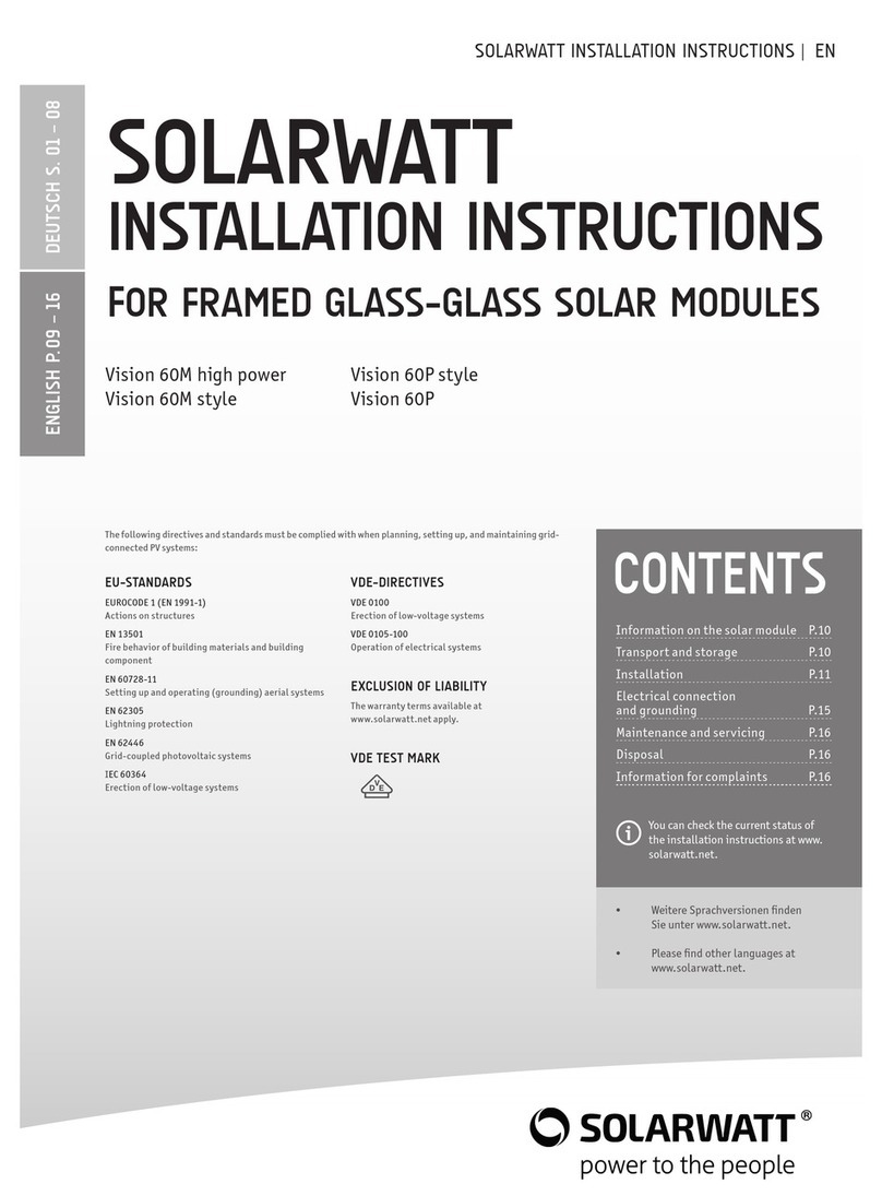
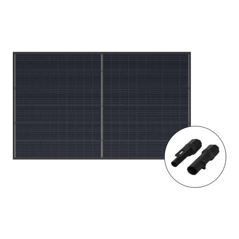
solarwatt Vision 60P style User manual

3 Weitere Sprachversionen finden
Sie unter www.solarwatt.de.
3 Please find other languages at
www.solarwatt.de.
DIN STANDARDS
DIN EN 1991-1 (DIN 1055)
Actions on structures
DIN EN 13501 (DIN 4102)
Fire behavior of building materials and building
components
DIN 18015
Electrical installations in residential buildings
DIN 18382
VOB Construction tendering and contract regulations
– Part C: General technical specifications for building
works (ATV) – low- and medium voltage systems with
nominal voltage up to 36 kV
DIN 43870
Meter panels
DIN EN 60728-11
(VDE 0855-1) Setting up and operating (grounding)
aerial systems
DIN EN 62305 (VDE 0185-305)
Lightning protection
DIN EN 62446
Grid-coupled photovoltaic systems
VDE PROVISIONS
DIN VDE 0100-510
Erection of low-voltage systems – Part 5-51: select-
ing and setting up electrical equipment – general
provisions
Information on the solar module P.10
Transport and storage P.11
Installation P.11
Electrical connection
and grounding P.15
Maintenance and servicing P.16
Disposal P.16
Information for complaints P.16
CONTENTS
You can check the current status of
the installation instructions at www.
solarwatt.de.
The following guidelines, directives, and DIN standards must be complied with when planning, setting up, and
maintaining grid-connected PV systems:
DIN VDE 0100-712
Erection of low-voltage systems – Part 7-712:
Requirements for special installations or locations –
solar photovoltaic (PV) power supply systems
DIN VDE 0100-737
Erection of low-voltage systems – damp and wet
areas and rooms and outdoor systems
DIN VDE 0105-100
Operation of electrical systems
PROPERTy INSURER DIRECTIVES (VDS)
VDS 2023
Guidelines for fire protection in structural systems
VDS 2024
Guidelines for fire protection for
the installation of electrical equipment in fixtures
ExCLUSION Of LIABILITy
The warranty terms available at www.solarwatt.de
apply.
VDE TEST MARK
inStallation inStRuctionS
DEUTSCH S. 01 – 08ENGLISH P. 09 – 16
SOLARWATT
BLUE ROOf
SOLUTION
SolaRWatt Blue 60P | SolaRWatt Blue 60M

These instructions describe the assembly, connection,
maintenance, and disposal of solar modules. Please read them
carefully and comply with them accordingly.
The installation and electrical connection of photovoltaic
systems may only be carried out by specialist personnel,
who are familiar with this work through their professional
qualifications. For the installation of the other components,
comply with the relevant installation instructions from the
manufacturer. The manufacturer is unable to monitor whether
these instructions and the conditions and methods for instal-
lation, operation, use, and maintenance of the inverter are
complied with.
Incorrect installation can cause damage to property, which
could consequently pose a risk to people. SOLARWATT accepts
no responsibility or liability for losses, damage, or costs
resulting from incorrect installation, operation, use, or
maintenance or losses, damage, or costs which are connected
to any of the above in any way. The SOLARWATT installation
instructions should be made available to the operator as part
of the solar power system documentation and stored by the
operator.
Comply with the guidelines, laws, and regulations valid in the
relevant country when planning, setting up, and operating
grid-connected PV systems. For information on additional re-
quirements, please contact the responsible local authorities
and the network operator.
SOLARWATT solar modules are made from high-quality
materials and high-performance solar cells, and are therefore
extremely reliable. The quality of the solar modules made
exclusively in Germany is ensured by multiple tests carried
out on the products throughout the entire production pro-
cess. SOLARWATT solar modules are VDE-tested and fulfill the
requirements of the extended test standard IEC 61215 Ed.2,
as well as the safety standard IEC 61730. In SOLARWATT's
own research and development department, tests are carried
out using measuring, testing, and environmental simulation
equipment which go above and beyond the current valid
standards and enable us to optimize our products continually.
If treated correctly, your SOLARWATT solar modules will offer
you several decades of service.
SOLARWATT recommends insuring the PV system against
reduced yields or damage with SOLARWATT Full Coverage for
complete security. Further information is available from your
SOLARWATT partner or online at www.solarwatt.de.
Information on the solar module
Detailed electrical and mechanical properties for your specific
module type can be found on the relevant data sheet. The key
technical data under standard test conditions [STC, solar cell
temperature: 25°C, irradiation: 1,000 Watt/m², air mass: 1.5
(corresponds to a sun elevation angle of 41.8°)] can also be
found on the nameplate of the solar module.
CONGRATULATIONS ON THE
PURCHASE Of yOUR SOLARWATT SOLAR MODULE
WARNING
Failure to comply with the installation instructions results in the warranty and
guarantee becoming null and void.
STATUS: 06/2012 |
INSTALLATION INSTRUCTIONS
Rev. 5 | Subject to change | © 2012 SOLARWATT AG
10
NOTE
TRANSPORT AND STORAGE
WARNING
The solar module is a glass product and should be handled with appropriate
care. Do not stand on the solar module. Do not allow any objects to fall or
place any objects on the solar module, as it can cause microcracks in the cells.
The rear side in particular must be protected from scratches and similar. Never
hold or transport the solar module by the junction box or connection cables.
Do not remove any parts or name-
plates from the solar module. Do
not install damaged solar modules.
SOLARWATT solar modules are made from high-quality materi-
als and are therefore extremely stable and long-lasting. This
means that, together with the environmentally-friendly,
resource-saving QUICKSTAXX® packaging solution, safe
transportation (tested in accordance with ISTA 3E) and easy
commissioning are guaranteed. The solar modules should nev-
ertheless be left in the packaging until installation to help
prevent any damage. The modules should be stored in a dry
place and protected from weather conditions. The packaging
(film, tape, pallet, etc.) should be recycled. Contact the
responsible local waste disposal company.
The fully biodegradable QUICKSTAXX® packaging edges can
be disposed of as household waste or in a suitable compost
system. Further information is available in the SOLARWATT
product information "Packaging" at www.solarwatt.de.
PROCEDURE IN THE
EVENT Of TRANSPORT DAMAGE
You are responsible for checking the goods and packag-
ing for transport damage immediately on receipt. If any
damage is discovered, note it on the shipping papers
describing each pallet in detail, and take photographs
as documentary evidence. Have the driver countersign
these notes. If more than ten solar modules on one pal-
let are damaged, refuse to accept the pallet. Please fill
out the "Transport Damage Complaint Notification" form
(www.solarwatt.de) and return it to SOLARWATT AG.
INSTALLATION
During installation, please take into account the locally valid
construction regulations, accident prevention regulations,
the relevant, generally accepted rules of technology and
safety regulations for working on roofs and buildings, as well
as electrical installations.
SOLARWATT solar modules must be fixed to suitable substruc-
tures, which are designed for the relevant mechanical wind
and snow loads, as well as the weight of the solar modules.
The instructions from the installation system manufacturer
must also be complied with. No mechanical stresses from the
actual building (e.g., roof truss) must be transferred to the
solar module. Have the structural suitability of the building
for the installation of a solar power system checked by a
specialist. The frame must not be mechanically or chemically
processed.
During installation, avoid creating shades with the module
clips or installation system to improve the energy yield.
Comply with the minimum distance of 5 mm between the
solar modules to allow the material to expand without
tension. SOLARWATT BLUE Line solar modules fulfill all the
requirements of the extended test standard IEC 61215 Ed.2,
11
STATUS: 06/2012 |
INSTALLATION INSTRUCTIONS
Rev. 5 | Subject to change | © 2012 SOLARWATT AG

SCREW fIxTURES
Fastening on the fastening holes with screws.
Only use the holes provided in the frame (diameter: 9 mm).
1
including the increased pressure load of 5,400 Pa, making
them ideal for use in areas with large amounts of snow. The
local regulations or the standard DIN EN 1991-1 (DIN 1055)
should be used for the calculation of the snow loads on the
module. It is important to note that these standards are
designed for impact on structures and do not explicitly take
into account the installation of solar modules.
In regions with particularly high snowfall, the pressure load
calculated in accordance with the standard based on local
snow load information may be significantly exceeded due
to snow overhang or build-up on the solar modules, which
could result in above-average stress on the bottom frame
edge. SOLARWATT therefore tests its modules above and
beyond the standard IEC 61215 Ed.2 and in accordance with
additional standards, taking into account additional loads in
the event of snow overhang or build-up to reflect the actual
loads encountered in practice and to ensure that our products
work safely throughout their entire service life. The maximum
pressure loads for the fastening methods listed below already
take into account these increased requirements and can be
regarded as the maximum pressure load in the installation
conditions taking into account the shape coefficients in ac-
cordance with DIN EN 1991-1 (DIN 1055).
NOTE
The solar module heats up during opera-
tion. Ensure that there is sufficient rear
ventilation to avoid reductions in yield.
Also ensure that no flammable gases can
escape or accumulate close by.
NOTE
WARNING
The solar modules are not designed
for concentrated irradiation. Bundling
or concentrating solar irradiation
through lenses or mirrors is therefore
not permitted and can damage the solar
modules.
The drainage holes in the module frame
must not be covered, as it could cause
frost damage on the module frame. Ensure
that water cannot run constantly towards
the cable screws or plug connectors. Do
not place any plug connectors in the
frame for this reason.
Fastening on the fastening holes
The maximum pressure load taking into account
the shape coefficients in accordance with DIN EN
1991-1 (DIN 1055) for the installation conditions
is 2,400 N/m².
The SOLARWATT BLUE ROOF SOLUTION solar modules can be
fastened in a number of ways:
STATUS: 06/2012 |
INSTALLATION INSTRUCTIONS
Rev. 5 | Subject to change | © 2012 SOLARWATT AG
12

SCREW fIxTURES
Fastening on the fastening holes with screws.
CLAMPING SySTEM
Fix in place with suitable module clips
2
The bracket must not distort the solar
module and the clips must not come
into contact with the front pane. Please
pay attention to the clip manufacturer’s
specifications. The clip surfaces must be
sufficiently sized (areas of 500 mm² per
fastening point are required).
NOTE
SOLARWATT solar modules are not regulated construction products in the sense of DIBt
(German Institute for Building Technology). It is not permitted to use SOLARWATT
solar modules as overhead glazing. For roof installation, the solar modules may only be
installed over a fire-resistant roof covering ("hard roof").
areas approved for fastening
Fastening on long sides
The maximum pressure load taking into
account the shape coefficients in accordance
with DIN EN 1991-1 (DIN 1055) for the instal-
lation conditions is 2,400 N/m².
Fastening on short sides
The maximum pressure load taking into
account the shape coefficients in accordance
with DIN EN 1991-1 (DIN 1055) for the instal-
lation conditions is 2,400 N/m².
Fastening on long sides
The maximum pressure load taking into account
the shape coefficients in accordance with DIN EN
1991-1 (DIN 1055) for the installation conditions is
3,500 N/m².
Fastening on short sides
In addition, this fastening mode requires a central,
round or linear support on the lower frame side (cen-
tral support). The maximum pressure load taking into
account the shape coefficients in accordance with
DIN EN 1991-1 (DIN 1055) for the installation condi-
tions is 2,400 N/m².
Vertical installation
Horizontal installation
100
mm
100
mm
200
mm
200
mm
100
mm
100
mm
100
mm
100
mm
200
mm
200
mm
13
STATUS: 06/2012 |
INSTALLATION INSTRUCTIONS
Rev. 5 | Subject to change | © 2012 SOLARWATT AG

INSERTION SySTEM
Fixed in place by inserting in a supporting frame
3
WARNING
Solar modules generate electrical energy on the front side during incidence of light. A
system with multiple solar modules can generate life-threatening voltages and electri-
cal currents. Do not touch the electrical connections or cable ends while the solar
module is exposed to light.
Vertical installation
The maximum pressure load taking into account
the shape coefficients in accordance with DIN EN
1991-1 (DIN 1055) for the installation conditions is
2,400 N/m².
STATUS: 06/2012 |
INSTALLATION INSTRUCTIONS
Rev. 5 | Subject to change | © 2012 SOLARWATT AG
14

ELECTRICAL CONNECTION AND GROUNDING
SOLARWATT solar modules are equipped at the factory with
high-quality solar cables and reverse-polarity protected,
shock-proof plug connectors. No others may be used. When
connecting the modules, ensure that the plugs engage with
an audible click.
To ensure that the products are safe and comply with the
technical data, only genuine tools from the relevant manu-
facturer may be used when self-assembling solar cables. The
solar cables must be compatible with the module plug system
of the relevant manufacturer.
The recommended maximum number of solar modules in-
stalled in series is 25. The recommended maximum number of
solar modules installed parallel is three (without string fuse).
Please comply with the value specified in the data sheet for
reverse-current feed and only use standardized photovoltaic
cables (recommendation: at least 4 mm² cable cross-section).
The solar modules correspond to application class A and can
therefore be operated in systems with dangerous DC voltages
(larger than 120 VDC in accordance with IEC 61730) and servic-
es. Solar modules in this application class can be used in sys-
tems with unrestricted access, the relevant regulations must
be complied with. SOLARWATT solar modules qualified within
this application class in accordance with IEC 61730 fulfill the
requirements of protection rating II with correct electrical
installation.
WARNING
The plug contacts must not be con-
nected or disconnected under load.
Failure to comply with this warning
could result in DEATH!
NOTE
It is advisable to install lightening protection in exposed locations. The solar modules
should be incorporated in existing lightening protection equipment. For this, take into
account the relevant valid regulations (e.g., DIN EN 62305, VDE V 0185-305 and in par-
ticular DIN EN 62305- 3 Supplement 5 "Lighting and overvoltage protection for photo-
voltaic power supply systems"). The maximum open circuit voltage for the solar genera-
tor must not be higher than the specified maximum system voltage of the solar module.
Module schematic, front view
Connection lines
String connector
Junction box with bypass diodes
Cell connector
Solar cells
15
STATUS: 06/2012 |
INSTALLATION INSTRUCTIONS
Rev. 5 | Subject to change | © 2012 SOLARWATT AG

NOTES ON COMPLAINTS
If you still have cause for complaint despite the high quality of our products,
please contact your dealer directly or:
SOLARWATT AG | Maria-Reiche-Str. 2a | 01109 Dresden | Germany
Tel. + 49 351 8895-0 | Fax + 49 351 8895-111 | info@solarwatt.de
Certified in accordance with ISO 9001 and ISO 14001
A photovoltaic system needs practically no maintenance,
as the solar modules are cleaned by the rain at the recom-
mended minimum angle of 15°. To avoid reductions in yield,
we do, however, recommend carrying out a regular visual
check on the module surfaces. Particularly heavy soiling
(e.g., leaves) can cause shades which reduce performance
and should therefore be removed. Clean the glass surface
with water and a soft sponge only. In exceptional cases, a
conventional cleaning agent may also be used in the recom-
mended dose. Do not use aggressive cleaning agents or met-
al objects, as they can be particularly damaging to the hard-
ened glass surface. The electric cables should (where acces-
sible) be checked regularly for damage, corrosion, and firm
hold. Pay particular attention to BGV A3, DIN VDE 0105-100.
MAINTENANCE AND SERVICING
DISPOSAL
Dispose of defective or old solar modules properly; they
should never be disposed of with domestic waste. For this
reason, we offer our customers return and recycling of our
solar modules. Contact us by e-mail at info@solarwatt.de
and specify the number and type of modules to be returned.
We will then coordinate all further details for returning your
modules.
Detailed view ground connection:
Fixing screw M4
Ring cable lug with ground cable
Toothed locked washer
Module frame with hole
for grounding (ø 4.2 mm)
Spring washer
Nut
In installation conditions, a solar module can deliver a high-
er current and/or higher voltage than under standardized
test conditions. Consequently, the short circuit current ISC
and open circuit voltage UOC specified on the solar modules
should be multiplied by 1.25 to determine the rated voltage
values of components, the rated current values of conduc-
tors, and the size of fuses and to measure controls connect-
ed to the solar modules.
Any type of soiling on the plug contacts before or after in-
stallation (dust, moisture, aerosols containing salt, etc.)
has a negative influence on the system function over the in-
tended service period. For this reason it is necessary to pay
particular attention to cleanliness during installation. The
use of lubricants is not permitted. Always protect unplugged
connectors against soiling of any type during transport,
storage, and during installation, as the connectors only sat-
isfy the requirements for their protection category when
plugged in. It is forbidden to open the junction box or modi-
fy or remove the cable or frame.
The minimum bend radius for the connection cable is 60 mm.
The cables must be laid so that mechanical strain on the
conductors and connections is ruled out. Take into account
the product-specific length of the connection cable specified
in the relevant data sheets at www.solarwatt.de
Potential equalization of the solar generator is prepared in
the factory and is recommended. It can be carried out using
the existing grounding bores on the long sides of the frame
in accordance with the valid local regulations.
STATUS: 06/2012 |
INSTALLATION INSTRUCTIONS
Rev. 5 | Subject to change | © 2012 SOLARWATT AG
16
Other manuals for Vision 60P style
2
This manual suits for next models
1
Table of contents
Other solarwatt Solar Panel manuals

solarwatt
solarwatt BLACK 60M STYLE User manual

solarwatt
solarwatt 36M glass User manual

solarwatt
solarwatt Vision 60P style User manual

solarwatt
solarwatt BLUE 60M User manual

solarwatt
solarwatt Panel vision AM 3.0 User manual

solarwatt
solarwatt Blue 60P/M User manual

solarwatt
solarwatt VISION 36M GLASS User manual

solarwatt
solarwatt Vision 60M high power User manual

solarwatt
solarwatt Vision 60P style User manual

solarwatt
solarwatt Vision 60M high power User manual