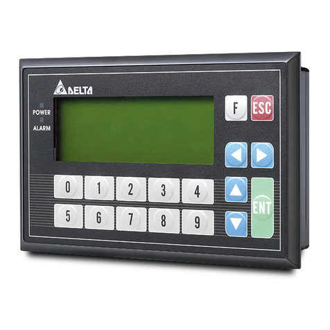
Delta DVP02TK-S User manual

www.deltaww.com
DVP02TK-S / DVP02TU-S
Temperature
Control Module Manual
*We reserve the right to change the information in this catalogue without prior notice.
Industrial Automation Headquarters
Taiwan: Delta Electronics, Inc.
Taoyuan Technology Center
No.18, Xinglong Rd., Taoyuan District,
Taoyuan City 33068, Taiwan
TEL:+886-3-362-6301 / FAX:+886-3-371-6301
Asia
China: Delta Electronics (Shanghai)Co., Ltd.
No.182 Minyu Rd., Pudong Shanghai, P.R.C.
Post code : 201209
TEL: +86-21-6872-3988 / FAX: +86-21-6872-3996
Customer Service: 400-820-9595
Japan: Delta Electronics (Japan), Inc.
Industrial Automation Sales Department
2-1-14 Shibadaimon, Minato-ku
Tokyo, Japan 105-0012
TEL: +81-3-5733-1155 / FAX: +81-3-5733-1255
Korea: Delta Electronics (Korea), Inc.
1511, 219, Gasan Digital 1-Ro., Geumcheon-gu,
Seoul, 08501 South Korea
TEL: +82-2-515-5305 / FAX: +82-2-515-5302
Singapore: Delta Energy Systems (Singapore)Pte Ltd.
4 Kaki Bukit Avenue 1, #05-04, Singapore 417939
TEL: +65-6747-5155 / FAX: +65-6744-9228
India: Delta Electronics (India)Pvt. Ltd.
Plot No.43, Sector 35, HSIIDC Gurgaon,
PIN 122001, Haryana, India
TEL: +91-124-4874900 / FAX: +91-124-4874945
Thailand: Delta Electronics (Thailand)PCL.
909 Soi 9, Moo 4, Bangpoo Industrial Estate (E . P. Z ),
Pattana 1 Rd., T.Phraksa, A.Muang,
Samutprakarn 10280, Thailand
TEL: +66-2709-2800 / FAX: +66-2709-2827
Australia: Delta Electronics (Australia)Pty Ltd.
Unit 20-21/45 Normanby Rd., Notting Hill Vic 3168, Australia
TEL: +61-3-9543-3720
Americas
USA: Delta Electronics (Americas)Ltd.
5101 Davis Drive, Research Triangle Park, NC 27709, U.S.A.
TEL: +1-919-767-3813 / FAX: +1-919-767-3969
Brazil: Delta Electronics Brazil
Rua Itapeva, 26 - 3°, andar Edicio Itapeva,
One -Bela Vista 01332-000 -São Paulo -SP -Brazil
TEL: +55-12-3932-2300 / FAX: +55-12-3932-237
Mexico: Delta Electronics International Mexico S.A. de C.V.
Gustavo Baz No. 309 Edicio E PB 103
Colonia La Loma, CP 54060
Tlalnepantla, Estado de México
TEL: +52-55-3603-9200
EMEA
EMEA Headquarters: Delta Electronics (Netherlands)B.V.
Sales: Sales.IA.EMEA@deltaww.com
Marketing: Marketing.IA.EMEA@deltaww.com
Technical Support: iatechnicalsupport@deltaww.com
Customer Support: Customer-Support@deltaww.com
Service: Service.IA.emea@deltaww.com
TEL: +31(0)40 800 3900
BENELUX: Delta Electronics (Netherlands)B.V.
Automotive Campus 260, 5708 JZ Helmond, The Netherlands
Mail: Sales.IA.Benelux@deltaww.com
TEL: +31(0)40 800 3900
DACH: Delta Electronics (Netherlands)B.V.
Coesterweg 45, D-59494 Soest,Germany
Mail: Sales.IA.DACH@deltaww.com
TEL: +49(0)2921 987 0
France: Delta Electronics (France)S.A.
ZI du bois Challand 2, 15 rue des Pyrénées,
Lisses, 91090 Evry Cedex, France
Mail: Sales.IA.[email protected]
TEL: +33(0)1 69 77 82 60
Iberia: Delta Electronics Solutions (Spain)S.L.U
Ctra. De Villaverde a Vallecas, 265 1º Dcha Ed.
Hormigueras – P.I. de Vallecas 28031 Madrid
TEL: +34(0)91 223 74 20
Carrer Llacuna 166, 08018 Barcelona, Spain
Mail: Sales.IA.Iberia@deltaww.com
Italy: Delta Electronics (Italy)S.r.l.
Via Meda 2–22060 Novedrate(CO)
Piazza Grazioli 18 00186 Roma Italy
Mail: Sales.IA.It[email protected]
TEL: +39 039 8900365
Russia: Delta Energy System LLC
Vereyskaya Plaza II, ofce 112 Vereyskaya str.
17 121357 Moscow Russia
Mail: Sales.IA.RU@deltaww.com
TEL: +7 495 644 3240
Turkey: Delta Greentech Elektronik San. Ltd. Sti. (Turkey)
Şerifali Mah. Hendem Cad. Kule Sok. No:16-A
34775 Ümraniye – İstanbul
Mail: Sales.IA.Turkey@deltaww.com
TEL: + 90 216 499 9910
MEA: Eltek Dubai (Eltek MEA DMCC)
OFFICE 2504, 25th Floor, Saba Tower 1,
Jumeirah Lakes Towers, Dubai, UAE
Mail: Sales.IA.MEA@deltaww.com
TEL: +971(0)4 2690148
DVP-0002220-04
2021/05/03

DVP02TK-S/DVP02TU-S
Temperature Control Module Manual
Revision History
Version Revision Date
1st The first version was published. 2016/11/30
2nd The second version was published. 2017-12-06
3rd 1.Updated specifications.
2.Update device information in chapter 2. 2019/02/20
4th
1.Update the information in chapter 1: Add Ni200 to
thermal resistance; add -100~+100mV to voltage
input; add information of microvolt input to A/D
function specification; add quick AI information to
analog sampling time; update wiring diagrams; update
description of DVP02TK-S dimension.
2.Update information concerning
CR#8/CR#9/CR#10/CR#11~#42 in chapter 2.1.3.
3.Update information concerning CR#11/CR#23/CR#24 in
chapter 2.1.4.
4.Update information concerning CR#13/CR#27~CR#35 in
chapter 2.1.5 and add information of
CR#26/CR#36/CR#37.
5.Update information concerning CR#13/CR#26 and add
information of CR#27~CR#29 in chapter 2.1.6.
6.Add chapter 2.1.11 Automatic PID Calculation Setup
page.
7.Add chapter 2.2 Examples of Setting a Control Register.
8.Update the information in chapter 2.3: Add mode28 and
29 to Current /Voltage; add mode27 to Nickel thermal
resistance.
9.Add content of PID Tuning Guide in chapter 2.6.
10.Add chapter 2.9 Automatic PID Calculation Feature.
2021/04/28


i
DVP02TK-S / DVP02TU-S
Temperature Control Module Manual
Chapter 1 Introduction
1.1 Specification......................................................................................1-3
1.2 Dimensions (mm)..............................................................................1-7
1.2.1 DVP02TU-S.................................................................................. 1-7
1.2.2 DVP02TK-S.................................................................................. 1-8
1.3 Installation........................................................................................1-9
1.4 Terminal arrangement.......................................................................1-9
1.5 Wiring Diagram ...............................................................................1-10
1.6 LED Indicator Description................................................................1-13
1.7 RS-485 Communication for DVP02TK-S Series ................................1-13
Chapter 2 Control Register
2.1 Control Registers...............................................................................2-3
2.1.1 MODBUS Address List for DVP02TK-S Series..................................... 2-3
2.1.2 MODBUS Hex Address List for DVP02TK-S Series............................... 2-3
2.1.3 List of the Control Registers ........................................................... 2-4
2.1.4 Basic Setup Page.......................................................................... 2-6
2.1.5 PID Setup Page .......................................................................... 2-10
2.1.6 Program Control Setup Page......................................................... 2-12
2.1.7 Pattern0, 1 Setup Page................................................................ 2-13
2.1.8 Pattern2, 3 Setup Page................................................................ 2-14
2.1.9 Pattern4, 5 Setup Page................................................................ 2-15
2.1.10 Pattern6, 7 Setup Page................................................................ 2-16
2.1.11 Automatic PID Calculation Setup Page ........................................... 2-18
2.2 Examples of Setting a Control Register ...........................................2-19
2.3 Analog Input Description.................................................................2-20
2.4 Outputs ...........................................................................................2-21

ii
2.4.1 The output value varies with the PV value. ..................................... 2-21
2.4.2 Alarm Outputs............................................................................ 2-21
2.5 ON/OFF Control Mode......................................................................2-23
2.6 PID Control Mode ............................................................................2-24
2.7 Programmable SV Control Mode ......................................................2-28
2.8 ERROR LED Indicator.......................................................................2-28
2.9 Automatic PID Calculation Feature..................................................2-29
2.9.1 Feature Description..................................................................... 2-29
2.9.2 Setup Instructions ...................................................................... 2-29
2.9.3 Additional Instruction .................................................................. 2-30
2.10 RS-485 Communication Setup for DVP02TK-S.................................2-30
2.10.1 MODBUS Communication Protocol .................................................... 2-30
2.10.2 Restore to Factory Settings.............................................................. 2-30
2.10.3 RS-485 Communication Setup ......................................................... 2-30
2.11 TK Wizard – Connection Setup.........................................................2-33
2.11.1 Restore to Factory Settings for DVP02TK-S ........................................ 2-33
2.11.2 COMMGR Set Up............................................................................ 2-33
2.11.3 Settings in TKSoft.......................................................................... 2-33
2.11.4 TKSoft – Scan the Connected Devices............................................... 2-34

1-1
1
Chapter 1 Introduction
Table of Contents
1.1 Specification......................................................................................1-3
1.2 Dimensions (mm)..............................................................................1-7
1.2.1 DVP02TU-S.................................................................................. 1-7
1.2.2 DVP02TK-S..................................................................................1-8
1.3 Installation........................................................................................1-9
1.4 Terminal arrangement.......................................................................1-9
1.5 Wiring Diagram ...............................................................................1-10
1.6 LED Indicator Description................................................................1-13
1.7 RS-485 Communication for DVP02TK-S Series ................................1-13

DVP02TK-S/DVP02TU-S Temperature Control Module Manual
1-2
_1
Thank you for using Delta DVP02TK-S/DVP02TU-S Temperature Control Module. To ensure a successful installation and
for safety reasons, please read this manual carefully before operating.
This manual contains important safety instructions.
Cette notice contient des instructions importantes concernant la sécurité.
Disconnect all sources of supply before servicing.
Couper toutes les sources d’alimentation avant de faire l’entretien et les réparations.
For use in a controlled environment. Refer to manual for environmental conditions.
Pour utilisation en atmosphère contrôlée. Consulter la notice technique.
Warning: proper ventilation is required to reduce the risk of hazardous or explosive gas buildup during indoor charging.
Avertissement : une ventilation adéquate est nécessaire afin de réduire les risques d’accumulation de gaz dangereux
ou explosifs durant la recharge à l’intérieur.
The analog input circuits shall not be connected to MAINS CIRCUIT for measuring or sensing and limited to SELV
circuit only.
The supply voltage and transistor (analog) outputs are SELV circuit and limited energy.
This is an OPEN TYPE module and therefore should be installed in an enclosure free of airborne dust, humidity, electric
shock and vibration. The enclosure should prevent non-maintenance staff from operating the device (e.g. key or
specific tools are required for operating the enclosure) in case danger and damage on the device may occur. Do not
touch any terminal when the power is on.
This manual provides you with the introductions on the specifications, installation, basic operations, setups and
temperature measurements.
Read this manual carefully and follow the instructions to avoid danger and damage to people and property.
DVP02TK-S series includes DVP02TKR-S, DVP02TKN-S and DVP02TKL-S. DVP02TU-S series includes
DVP02TUR-S, DVP02TUN-S and DVP02TUL-S.

Chapter 1 Introduction
1-3
1_
1.1 Specification
DVP02TK-S/DVP02TU-S
Supply voltage 24VDC
Max. rated power
consumption
2.4W, supplied by external power source in compliance with UL61010-2-201 \ IEC61131-2
Connector Type European standard removable terminal block (Pin pitch: 3.5mm)
Operation/storage
temperature
Operation: 0°C ~ 55°C (temperature), 5 ~ 95% (humidity), Pollution degree: 2
Storage: -25°C ~ 70°C (temperature), 5 ~ 95% (humidity), Attitude: up to 2000m;
For use in dry location only
Vibration/Shock
resistance International standards: IEC 61131-2, IEC 68-2-6 (TEST Fc) / IEC 61131-2 & IEC 68-2-27
(TEST Ea)
Connection to
DVP-PLC
The modules are numbered from 0 to 7 automatically by their distance from DVP-PLC. Max. 8
modules are allowed to connect to DVP-PLC and will not occupy any digital I/O points.
I/O points 2 points of universals analog inputs (CH1, CH2), 2 analog outputs (OUT1, OUT2) or 4 digital
outputs (OUT1~OUT4)
General Analog Input
Input CH1,
CH2
Thermal resistance: Pt100, JPt100, Pt1000, Ni100, Ni120, Ni1000, Cu50, Cu100, LG-Ni1000
Thermocouple : J, K, R, S, T, E, N, B, U, L, TXK (L), C, PL II
Voltage input: 0~+50mV, 100~+100mV, 0~+5V, 0~+10V
Current input: 0mA~+20mA, 4~+20 mA
Hardware Resolution
16 bits
Distance 100 meters
Input disconnection
detection Supported by exceeded temperature input range
Analog / Digital Output
Analog OUT1~
OUT2 Analog output, 12-bit: 0~+10V, 0/4~+20mA
Digital OUT1~
OUT4
4 channels digital output, 250VAC, 60Hz/24VDC, 2A, Relay
4 channels digital output, Voltage pulse output, 24VDC, 300mA
A/D Function Specification
Analog / Digital Voltage Input
Maximum rated input 0V~10V 0V~5V
Overall accuracy
(normal temperature) ±0.5%
Overall accuracy
(full temperature range) ±1%
Hardware resolution 16 bits
Input impedance 650KΩ

DVP02TK-S/DVP02TU-S Temperature Control Module Manual
1-4
_1
Analog / Digital Microvolt Input
Maximum rated input 0mV ~+50mV -100mV ~+100mV
Overall accuracy
(normal temperature) ±0.5%
Overall accuracy
(full temperature range) ±1%
Hardware resolution 16 bits
Input impedance 650KΩ
Analog / Digital Current Input
Maximum rated input 0mA~20mA 4mA~20mA
Overall accuracy
(normal temperature) ±0.5%
Overall accuracy
(full temperature range) ±1%
Hardware resolution 16 bits
Input impedance 249Ω
Analog / Digital Temperature Input
Maximum rated input Thermocouple Thermistor
Overall accuracy
(normal temperature) ±0.4%
Overall accuracy
(full temperature range) ±0.8%
Hardware resolution 24 bits
Input impedance 2MΩ
Analog sampling time (by channel)
Analog input type AI Thermocouple Thermistor Quick AI (0~10V)*2 Quick AI (4~20Ma)
Setting time (ms) 80 80 160 3 3
Conversion time (ms) 50 50 100 2 2
Response time (ms) 130 130 260 5 5
Response time = setting time + conversion time
*1. Compared to the response time of the thermocouple temperature, it needs two times of time for the thermistor
temperature to respond, since the thermistor channels require a temperature compensation.
*2. Since there is only one channel used, the time to stabilize the circuit is not required.

Chapter 1 Introduction
1-5
1_
DVP02TKL-S/DVP02TUL-S D/A Function Specification
Analog / Digital Voltage Output
Maximum rated input 0V~10V
Overall accuracy
(normal temperature) ±0.5%
Overall accuracy
(full temperature range) ±1%
Hardware resolution 12 bits
Allowable load
impedance 1kΩ~ 2MΩat 0V~10V
Analog / Digital Current Output
Maximum rated output 0mA~20mA 4mA~20mA
Overall accuracy
(normal temperature) ±0.5%
Overall accuracy
(full temperature range)
(average number of 100
times)
±1%
Hardware resolution 12 bits
Allowable load impedance
≦550Ω
Analog setup time (by channel)
Analog output type Voltage Current
Setting time (µs) 100 250
Conversion time (µs) 500 500
Response time (µs) 600 750
Response time = setting time + conversion time

DVP02TK-S/DVP02TU-S Temperature Control Module Manual
1-6
_1
DVP02TKR-S/DVP02TUR-S/DVP02TKN-S/DVP02TUN-S DO Function Specification
Model
Item
DVP02TKR-S
DVP02TUR-S
DVP02TKN-S
DVP02TUN-S
Output points 4 4
Connector Type Removable terminal block
Output point type Relay-R Transistor-T (NPN)
Voltage specification Below 250VAC, 30VDC 12~30VDC
Maximum load Resistive 2A/1point
(3A/COM)*1
0.3A/1 point
(0.6A/COM)*1
Inductive Life curves*2, 4 7.2W (24VDC)*3
Maximum
output
frequency
Resistive 1Hz 100Hz
Inductive 0.5Hz 0.5Hz
Lamp 1Hz 10Hz
Maximum
response time
OFF→ON 10ms 0.5ms
ON→OFF
*1. Complied with UL61010-2-201 & IEC61131-2 (AC or DC resistance)
*2. Complied with UL61010-2-201 & IEC61131-2 (AC/DC general-use or AC pilot duty)
Rated making capacity: 7.5A; rated breaking capacity: 0.75A; 2.5A thermal continuous at 240VAC
DC pilot duty; rated making capacity: 0.22A; rated breaking capacity: 0.22A; 1A thermal continuous at 30VDC
*3. Complied with IEC/UL61010-2-201 (DC general-use)
*4. Life curves
Disconnect power before servicing to avoid the risk of electric shock.
Utilisez relay est sous tension. Risque de choc électrique, couper le courant avant l’entretien.
Contact Current(A)
20
0.5
0.1 0.2
30
50
0.3 0.7 1 2
200
300
500
100
1000
2000
3000
Operation(X10)
3
120VAC Resistive
30VDC Inductive(t=7ms)
240VAC Inductive(cos 0.4)
ψ
=
120VAC Inductive(cos =0.4)
ψ
30VDC
Inductive
(t=40ms)

Chapter 1 Introduction
1-7
1_
1.2 Dimensions (mm)
1.2.1DVP02TU-S
8
DVP-02TU
1
2
3
4
6
5
7
3.40
60.00
90.00
25.20 60.00 3.00
3.00
3.00
Description
1 Run/Error indicator
2 Model name
3 Removable terminal block
4 I/O terminal layout
5 I/O module clip
6 I/O module connection port
7 Label
8 DIN rail clip

DVP02TK-S/DVP02TU-S Temperature Control Module Manual
1-8
_1
1.2.2DVP02TK-S
8
1
2
3
4
6
7
3.40
60.00
90.00
25.20 60.00 3.00
3.00
3.00
5
9
10 11
Description
1 Run/Error indicator
2 Model name
3 Removable terminal block
4 I/O terminal layout
5 Run/Stop switch
6 I/O module extension port
7 Label
8 DIN rail clip
9 I/O module clip
10 Power connection port
11 RS-485 communication port

Chapter 1 Introduction
1-9
1_
1.3 Installation
Users can connect DVP02TU-S series modules to the right side of the DVP02TK-S series modules as the image shown
below. Up to DVP02TU-S can be connected.
DVP02TU-S
DVP02TK-S
1.4 Terminal arrangement
DVP02TKR-S/DVP02TKN-S
DVP02TUR-S/DVP02TUN-S DVP02TKL-S/DVP02TUL-S
CH1
CH2
L+
I+
.
.
O UT 1
L-
I-
L+
I+
L-
I-
S LD
O UT 2
C0
.
O UT 3
O UT 4
C1
L+
I+
.
.
VO
L-
I-
L+
I+
L-
I-
S LD
IO
AG
.
VO
IO
AG
CH1
CH2
OUT1
OUT2
Warning: DO NOT connect wires to the terminals with No Connection (marked by a dot symbol ).

DVP02TK-S/DVP02TU-S Temperature Control Module Manual
1-10
_1
Mounting Arrangements and Wiring Notes
Please install PLC in an enclosure with sufficient space around it to allow heat dissipation as shown in the figure.
DVP
MP
D
D
DD
D > 50 mm
Warning: shock hazard. Only for mounting in a rack or enclosure fully enclosing all live parts.
Avertissement : risque d’électrocution. Ne doit être installé que dans un bâti ou un boîtier recouvrant entièrement toutes
les pièces sous tension.
1.5 Wiring Diagram
22-16AWG
<1.5mm
1. Use 22-16AWG (1.5mm) single or multiple core wire on I/O wiring terminals. The specification of the terminal is
shown in the figure above. The PLC terminal screws shall be tightened to 1.95 kg-cm (1.7 in-lbs).
2. DO NOT place the I/O signal wires and power supply wire in the same wiring duct.
3. Warning: use conductors with insulation rated for at least 75 °c
Avertissement : employer des conducteurs pour au moins 75 °c.
4. For use with copper conductors only (excluding thermocouplers).
destiné à être utilisé avec des conducteurs en cuivre seulement (sauf thermocouples).
How to install DIN rail
DVP-PLC can be secured to a cabinet by using the DIN rail of 35mm in height and
7.5mm in depth. When mounting PLC to DIN rail, be sure to use the end bracket to
stop any side-to-side movement of PLC and reduce the chance of wires being
loosen. A small retaining clip is at the bottom of PLC. To secure PLC to DIN rail,
place the clip onto the rail and gently push it up. To remove it, pull the retaining clip
down and gently remove PLC from DIN rail, as shown in the figure.

Chapter 1 Introduction
1-11
1_
Sensor input wiring
電流輸出
AG
ADC
AG
INA
隔離線*1 CH1 L+
L-
I-
SLD
2-Wire
I+
SLD
3-Wire
L+
L-
I-
I+
Pt100/JPt100
/Pt1000 隔離線*1 CH2
Ni100/Ni1000/Ni120
LG-Ni1000/Cu50/Cu100
Pt100/JPt100/Pt1000
Shielded
Cable*1
Shielded
Cable*1
Current Output
Voltage/Current input wiring
電流輸出
AG
ADC
AG
INA
隔離線*1 CH1
CH2
0mV~+50mV,
0V~+5V,
0V~+10V
+
-
L+
L-
I-
SLD
I+
0mA~+20mA,
4mA~+20mA
+
-
L+
L-
I-
SLD
I+
-100mV~+100mV,
Shielded
Cable*1 Current Output

DVP02TK-S/DVP02TU-S Temperature Control Module Manual
1-12
_1
Thermocouple input wiring
AG
ADC
INA
+
-
L+
L-
I-
SLD
I+
Thermocouple Current Output
DVP02TKN-S/DVP02TUN-S Output point wiring
24VDC
+
D: 1N4001
Diode or equivalent component
D
OUT1
C0
OUT2
D
OUT3
C1
OUT4
24VDC
+
D: 1N4001
Diode or equivalent component
DVP02TKR-S/DVP02TUR-S Output point wiring
OUT3
C1
OUT4
240VAC
OUT3
C1
OUT4
24VDC

Chapter 1 Introduction
1-13
1_
DVP02TKL-S/DVP02TUL-S Output point wiring
OUT2
AG
OUT1
AG
CH1
CH2
VO
IO
AG
0V~+10V
VO
IO
AG
0mA~+20mA,
4mA~+20mA
RS-485 Wiring
D+ D- SG D+ D- SG SG D+ D-
M ast er Slave Slave
Terminal
impedaance
(120 ohm)
Shielded
cable*1
Shielded
c able *1
1.6 LED Indicator Description
LED Indicator
LED Color
Description
POWER
Green
Power status
A/D Green Operating status
ERROR Red Error display
OUT1~OUT4 Red Output status
1.7 RS-485 Communication for DVP02TK-S Series
Data Transmission
Speed
9,600; 19,200; 38,400; 57,600; 115,200bps
Communication
Format
Stop bit: 1, 2 Parity bit: None, Odd, Even Data bit: 7, 8
Communication
Protocool
MODBUS ASCII/RTU

DVP02TK-S/DVP02TU-S Temperature Control Module Manual
1-14
_1
MEMO

2-1
2
Chapter 2 Control Register
Table of Contents
2.1 Control Registers...................................................................... 2-3
2.1.1 MODBUS Address List for DVP02TK-S Series ................................2-3
2.1.2 MODBUS Hex Address List for DVP02TK-S Series ..........................2-3
2.1.3 List of the Control Registers.......................................................2-4
2.1.4 Basic Setup Page......................................................................2-6
2.1.5 PID Setup Page...................................................................... 2-10
2.1.6 Program Control Setup Page .................................................... 2-12
2.1.7 Pattern0, 1 Setup Page ........................................................... 2-13
2.1.8 Pattern2, 3 Setup Page ........................................................... 2-14
2.1.9 Pattern4, 5 Setup Page ........................................................... 2-15
2.1.10 Pattern6, 7 Setup Page......................................................... 2-16
2.1.11 Automatic PIDCalculation Setup Page .................................... 2-18
2.2 Examples of Setting a Control Register .................................. 2-19
2.3Analog Input Description.........................................................2-20
2.4Outputs .................................................................................. 2-21
2.4.1 The output value varies with the PV value.................................. 2-21
2.4.2 Alarm Outputs ....................................................................... 2-21
2.5ON/OFF Control Mode............................................................. 2-23
2.6PID Control Mode ................................................................... 2-24
2.7Programmable SV Control Mode ............................................. 2-28
2.8ERROR LED Indicator.............................................................. 2-28
2.9Automatic PID Calculation Feature......................................... 2-29
2.9.1 Feature Description ................................................................ 2-29
2.9.2 Setup Instructions.................................................................. 2-29
Other manuals for DVP02TK-S
1
This manual suits for next models
1
Table of contents
Other Delta Industrial Electrical manuals
Popular Industrial Electrical manuals by other brands

Murata
Murata GRT155C81C474KE01 Series Reference sheet

Murata
Murata GRM32ER71A476KE15 Series Reference sheet

Eaton
Eaton COOPER POWER SERIES Maintenance instructions

schmersal
schmersal AZM 161 AS operating instructions

Murata
Murata GJM0225C1E6R3DB01 Series Reference sheet

Sensorex
Sensorex SD7000 Series Product Instruction Sheet