INDEX Document code: DPD00899A
Date 19.01.2012
1. GENERAL ...........................................................................................................................3
2. RS-485 OPTION BOARD TECHNICAL DATA ........................................................................ 4
2.1 General ......................................................................................................................................... 4
3. RS-485 FIELDBUS BOARD LAYOUT AND CONNECTIONS...................................................5
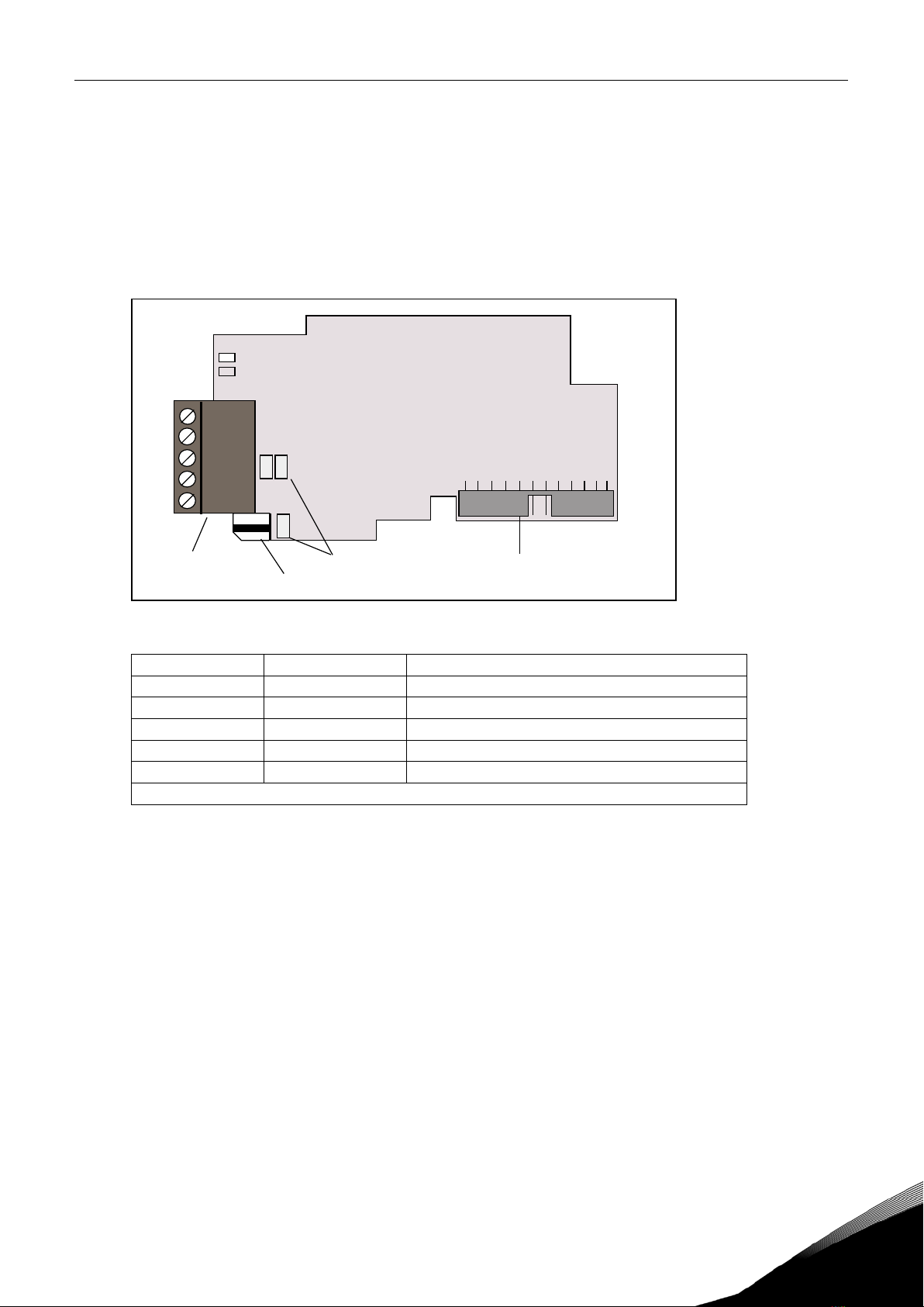
3.1 RS-485 OPTC2 option board ......................................................................................................... 5
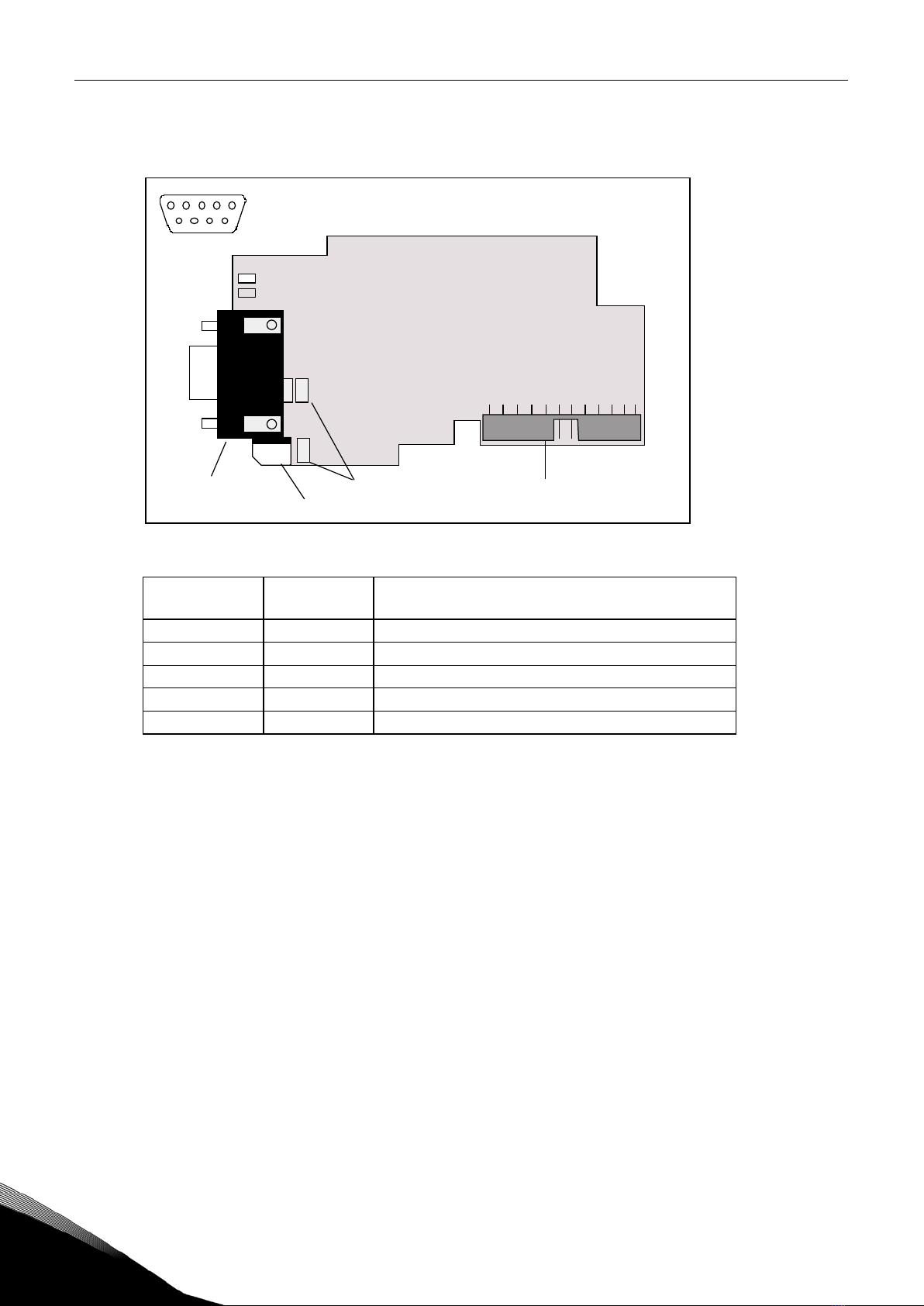
3.2 RS-485 OPTC8 option board ......................................................................................................... 6
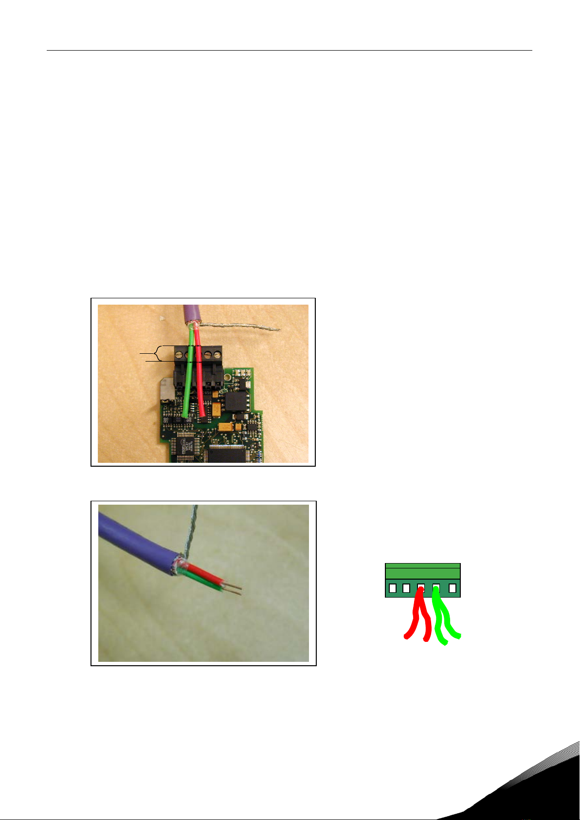
3.3 Grounding ..................................................................................................................................... 7
3.3.1 Grounding by clamping the cable to the converter frame.................................................7
3.3.2 Grounding only one point on the net..................................................................................9
3.3.3 Grounding jumper X1.......................................................................................................10
3.4 Bus terminal resistors................................................................................................................ 11
3.5 Bus Biasing................................................................................................................................. 12
3.6 LED indications........................................................................................................................... 13
4. INSTALLATION OF VACON NX RS-485 BOARD ................................................................. 14
5. COMMISSIONING.............................................................................................................. 16
5.1 Fieldbus board parameters........................................................................................................ 16
6. MODBUS........................................................................................................................... 19
6.1 Modbus RTU protocol, introduction............................................................................................ 19
6.1.1 Supported functions.........................................................................................................21
6.1.2 Exception responses........................................................................................................23
6.2 Modbus interface........................................................................................................................ 25
6.2.1 Modbus registers.............................................................................................................25
6.2.2 Process data ....................................................................................................................25
6.2.3 Process data in ................................................................................................................26
6.2.4 Process data out ..............................................................................................................27
6.2.5 Parameters......................................................................................................................30
6.2.6 Actual values....................................................................................................................30
6.2.7 Example messages..........................................................................................................31
6.3 Start-up test ............................................................................................................................... 33
7. METASYS N2..................................................................................................................... 34
7.1 Metasys N2 Protocol Introduction.............................................................................................. 34
7.2 Metasys N2 interface.................................................................................................................. 34
7.2.1 Analogue Input (AI) ..........................................................................................................34
7.2.2 Binary Input (BI)...............................................................................................................34
7.2.3 Analogue Output (AO).......................................................................................................35
7.2.4 Binary Output (BO)...........................................................................................................35
7.2.5 Internal Integer (ADI).......................................................................................................35
7.3 N2 POINT MAP............................................................................................................................ 36
7.3.1 Analogue Inputs (AI).........................................................................................................36
7.3.2 Binary Inputs (BI) .............................................................................................................37
7.3.3 Analogue Outputs (AO).....................................................................................................37
7.3.4 Binary Outputs (BO) .........................................................................................................38
7.3.5 Internal Integers (ADI) .....................................................................................................38
8. FAULT TRACKING............................................................................................................. 39
APPENDIX 1............................................................................................................................................ 40