Delta 31-484 User manual

31-484
Lijadora de piso de eje
oscilante de uso pesado
Ponceuse à broche oscillante
sur pied haute résistance
Instruction Manual
Manuel d’utilisation
Manual de instrucciones
Français (16)
Español (31)
INSTRUCTIVO DE OPERACIÓN, CENTROS
DE SERVICIO Y PÓLIZA DE GARANTÍA.
LÉASE ESTE INSTRUCTIVO
ANTES DE USAR EL PRODUCTO.
www.DeltaMachinery.com
HEAVY DUTY OSCILLATING
FLOOr SpINDLE SANDEr
STOP
ON

Failure to follow all instructions listed below, may result in electric shock, fire,
and/or serious personal injury or property damage.
Woodworking can be dangerous if safe and proper operating procedures are not followed. As with all
machinery, there are certain hazards involved with the operation of the product. Using the machine with
respect and caution will considerably lessen the possibility of personal injury. However, if normal safety
precautions are overlooked or ignored, personal injury to the operator may result. Safety equipment such
as guards, push sticks, hold-downs, featherboards, goggles, dust masks and hearing protection can reduce your
potential for injury. But even the best guard won’t make up for poor judgment, carelessness or inattention. Always
use common sense and exercise caution in the workshop. If a procedure feels dangerous, don’t try it. Figure out
an alternative procedure that feels safer. Your personal safety is your responsibility. For additional
information please visit our website
This machine was designed for certain applications only. DELTA®Power Equipment Corporation
strongly recommends that this machine not be modified and/or used for any application other than
that for which it was designed. If you have any questions relative to a particular application, DO NOT use the
machine until you have first contacted DELTA®to determine if it can or should be performed on the product.
If you have any questions relative to its application DO NOT use the product until you have written DELTA® Power
Equipment Corporation and we have advised you. Contact us online at www.DeltaMachinery.com or by mail at
Technical Service Manager, DELTA®Power Equipment Corporation, 4825 Highway 45 North, Jackson, TN 38305.
Information regarding the safe and proper operation of this tool is available from the following sources:
• Power Tool Institute, 1300 Sumner Avenue, Cleveland, OH 44115-2851or online at www.powertoolinstitute.com
• National Safety Council, 1121 Spring Lake Drive, Itasca, IL 60143-3201
• American National Standards Institute, 25 West 43rd Street, 4 floor, New York, NY 10036 www.ansi.org - ANSI 01.1
Safety Requirements for Woodworking Machines
• U.S. Department of Labor regulations www.osha.gov
MotorSpecifications........................................................... 5
GroundingInstructions....................................................... 5
ExtensionCords................................................................. 6
AttachtheMotorCover....................................................... 8
AttachtheSpindleTiltWheel.............................................. 8
AttachStorageHooks......................................................... 8
InstallSandingSleevesontoSpindles................................ 9
InstalltheSpindleontotheSander..................................... 9
SelectandInstalltheTableInsert..................................... 10
SquaretheTabletotheSpindle........................................ 11
ConnecttoaDustCollector............................................. 11
AdjusttheSpindleTilt....................................................... 13
AdjustThe90°and45°PositiveStops............................. 13
RoutineInspection............................................................. 14
Bearings............................................................................. 14
ChangingtheGearOil....................................................... 14
2

This manual contains information that is important for you to know and understand. This information relates to
protecting YOUR SAFETY and PREVENTING EQUIPMENT PROBLEMS. To help you recognize this information, we
use the symbols below. Please read the manual and pay attention to these sections.
Indicates an imminently hazardous situation which, if not avoided, will result in death or serious
injury.
Indicates a potentially hazardous situation which, if not avoided, could result in death or serious
injury.
Indicates a potentially hazardous situation which, if not avoided, may result in minor or moderate
injury.
Used without the safety alert symbol indicates potentially hazardous situation which, if not avoided,
may result in property damage.
•
Learn the unit’s application and limitations as well as the specific hazards peculiar to it.
• Cluttered areas and benches invite accidents.
• Don’t use this unit in damp or wet locations, or expose it to rain.
Keep work area well-lighted.
• All children and visitors should be kept a safe distance from work area.
• before servicing.
• Before further use of the unit, properly repair or replace any part that is damaged.
1. Read and understand the warnings posted on the
machine and in this manual. Failure to comply with
all of these warnings may cause serious injury.
2. Replace the warning labels if they become
obscured or removed.
3. This machine is designed and intended for use by
properly trained and experienced personnel only.
If you are not familiar with the proper and safe
operation of a heavy duty floor spindle sander, do
not use until proper training and knowledge have
been obtained.
4. Do not use this machine for other than its intended
use. If used for other purposes, DELTA®Power
Equipment Corporation disclaims any real or
implied warranty and holds itself harmless from any
injury that may result from that use.
5. Always wear approved safety glasses/face shields
while using this spindle sander.
6. Before operating this sander, remove tie, rings,
watches and other jewelry, and roll sleeves up past
the elbows. Remove all loose clothing and confine
long hair. Non-slip footwear or anti-skid floor strips
are recommended. Do not wear gloves.
7. Wear ear protectors (plugs or muffs) during
extended periods of operation.
8. Some dust created by power sanding, sawing,
grinding, drilling and other construction activities
contain chemicals known to cause cancer,
birth defects or other reproductive harm. Some
examples of these chemicals are:
• Lead from lead based paint.
• Crystalline silica from bricks, cement and other
masonry products.
• Arsenic and chromium from chemically treated
lumber.
To reduce your exposure to
these chemicals, work in a well-ventilated area and
work with approved safety equipment, such as face or
dust masks that are specifically designed to filter out
microscopic particles.
9. Do not operate this machine while tired or under
the influence of drugs, alcohol or any medication.
10.Make certain the switch is in the OFF position
before connecting the machine to the power
source.
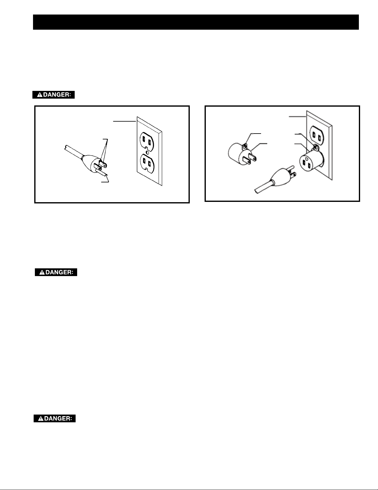
11.Make certain the machine is properly grounded.
12.Make all machine adjustments or maintenance with
the machine unplugged from the power source.
continued on page 4
3
5. Always wear approved safety glasses/face shields
while using this spindle sander.
6. Before operating this sander, remove tie, rings,
watches and other jewelry, and roll sleeves up past
the elbows. Remove all loose clothing and confine
long hair. Non-slip footwear or anti-skid floor strips
are recommended. Do not wear gloves.

13.Form a habit of checking to see that all extra
equipment such as adjusting keys, wrenches,
scrap, stock, and cleaning rags are removed away
from the machine before turning on.
14.Keep safety guards in place at all times when the
machine is in use. If removed for maintenance
purposes, use extreme caution and replace the
guards immediately when maintenance is complete.
15.Make sure the tool is firmly secured to the floor
before use.
16.Check damaged parts. Before further use of the
machine, a guard or other part that is damaged
should be carefully checked to determine that it will
operate properly and perform its intended function.
Check for alignment of moving parts, binding of
moving parts, breakage of parts, mounting and
any other conditions that may affect its operation.
A guard or other part that is damaged should be
properly repaired or replaced.
17.Provide for adequate space surrounding work area
and non-glare, overhead lighting.
18.Keep the floor around the machine clean and free of
scrap material, oil and grease.
19.Keep visitors a safe distance from the work area.
Keep children away.
20.Make your workshop child proof with padlocks,
master switches or by removing starter keys.
21.Give your work undivided attention. Looking
around, carrying on a conversation and “horse-
play" are careless acts that can result in serious
injury.
22.Maintain a balanced stance at all times so that you
do not fall or lean against the tool or its moving
parts. Do not overreach or use excessive force to
perform any machine operation.
23.Use the right tool at the correct speed and feed
rate. Do not force a tool or attachment to do a job
for which it was not designed. The right tool will do
the job better and safer.
24.Use recommended accessories; improper
accessories may be hazardous.
25.Maintain machinery with care. Follow instructions
for lubricating and changing accessories.
26.Turn off the machine before cleaning. Use a brush
or compressed air to remove dust or debris — do
not use your hands.
27.Do not stand on the machine. Serious injury could
occur if the machine tips over.
28.Never leave the machine running unattended. Turn
the power off and do not leave the machine until it
comes to a complete stop.
29.At all times, hold the stock firmly.
30.Always turn the sander on and allow it to come
up to full speed before allowing the workpiece to
contact the sanding surface.
31.Make sure to use the appropriate size table insert
for the sanding spindle selected.
32.Do not use this machine for other than it intended
use. If used for other purposes, DELTA®Power
Equipment Corporation disclaims any real or
implied warranty and holds itself harmless for any
injury or damage which may result from that use.
This means that if precautions are not heeded, it may
result in minor injury and/or possible machine damage.
This means that if precautions are not heeded, it may
result in serious injury or possibly even death.
4

A separate electrical circuit should be used for your machines. This circuit should not be less than #12 wire and
should be protected with a 20 Amp time lag fuse. If an extension cord is used, use only 3-wire extension cords
which have 3-prong grounding type plugs and matching receptacle which will accept the machine’s plug. Before
connecting the machine to the power line, make sure the switch (s) is in the "OFF" position and be sure that the
electric current is of the same characteristics as indicated on the machine. All line connections should make good
contact. Running on low voltage will damage the machine.
Your machine is wired for 115 volts, 60 HZ alternating current. Before connecting the machine to the power source,
make sure the switch is in the “OFF” position.
In the event of a malfunction or breakdown, grounding provides a path of least resistance for electric current to
reduce the risk of electric shock. This machine is equipped with an electric cord having an equipment-grounding
conductor and a grounding plug. The plug must be plugged into a matching outlet that is properly installed and
grounded in accordance with all local codes and ordinances.
Do not modify the plug provided - if it will not fit the outlet, have the proper outlet installed by a qualified electrician.
Improper connection of the equipment-grounding conductor can result in risk of electric shock. The conductor with
insulation having an outer surface that is green with or without yellow stripes is the equipment-grounding conductor.
If repair or replacement of the electric cord or plug is necessary, do not connect the equipment-grounding conductor
to a live terminal.
Check with a qualified electrician or service personnel if the grounding instructions are not completely understood,
or if in doubt as to whether the machine is properly grounded.
Use only 3-wire extension cords that have 3-prong grounding type plugs and matching 3-conductor receptacles that
accept the machine’s plug, as shown in Fig. A.
Repair or replace damaged or worn cord immediately.
5

RECOMMENDEDSIZESFORUSEWITHSTATIONARYELECTRICMACHINES
GREATERTHAN50FEETNOTRECOMMENDED
6
The DELTA®Heavy Duty Oscillating Floor Spindle Sander is designed for sanding or polishing flat, round, or curved
surfaces on wood, plastic materials.

7
Oscillation rate 60 Strokes Per Minute (SPM)
Oscillation stroke 1-1/2”
Spindle Speed 1725 RPM
Motor 1 HP, 110V, 10 Amps
Table Size 24 – 5/8” X 24 – 1/2”
Spindle Tilt 0° - 45°
Spindle Size Range 1/4”, 3/8”, 1/2”, 5/8”, 3/4”, 1”, 1-1/2”, 2”, 3”, 4”
Dust Chute 4”
Base Dimensions 24 – 3/4” X 19 – 3/4”
NET Weight 374 Lbs
The machine is heavy, be careful when removing it from the shipping container! Failure to comply
may cause serious injury and/or damage to the tool and/or property!
The machine is heavy, be careful when removing it from the shipping
container! Failure to comply may cause serious injury and/or damage to the machine and/or
property!
Your DELTA®Heavy Duty Oscillating Floor Spindle Sander comes packed in a single container. Use a safety strap to
avoid tip-over when lifting machine. Check shipping carton and machine for damage before unpacking.
1. Carefully cut the banding straps and remove them from the container.
2. Cut along the tape line at the top of the container.
3. Remove any loose parts accessible from the top of the container and set aside.
4. Cut vertically along each of the four sides of the container to fully expose the machine.
5. Remove any loose parts or hardware and set aside.
6. With the help of a second adult, carefully lift the machine off the pallet and onto a level floor surface.
7. Compare all parts to the list below and check that all parts are present and in good condition.
• Floor spindle sander (1)
• Motor cover (1)
• Steel spindles and sanding
sleeves (4) (Diameter - 1/4”,
3/8”, 1/2”, 5/8”)
• Rubber spindles and sanding
sleeves (6) (Diameter - 3/4”, 1”,
1-1/2”, 2”, 3”, 4”)
• Oblong table inserts (3 (small,
medium, large)
• Round table inserts (3) (small,
medium, large)
• Open end spindle wrenches (2
• Storage hooks (2)
• Spindle tilt wheel (1)
• Spindle tilt retaining knob (1)
• Hardware package (1)
• Owner’s manual (1) (not shown)
Report any missing or damaged parts to your distributor or dealer. Prior to tool assembly and use, read this manual
thoroughly to familiarize yourself with proper assembly, maintenance and safety procedures.
Remove any protective materials and coatings from all of the parts and the sander. The protective coatings can be
removed by spraying WD-40 on them and wiping it off with a soft cloth. This may need redone several times before
all of the protective coatings are removed completely.
If any parts are missing, do not attempt to plug in the power cord and turn “ON” the machine. The
machine should only be turned “ON” after all the parts have been obtained and installed correctly.
• 3mm Hex Wrench (1)
• 4mm Hex Wrench (1)
• 6mm Hex Wrench (1)
• 12mm Open Wrench (1)

8
1. Slide the hinge pins (A) in the motor cover into the
hinge holes located on the motor housing.
2. Carefully press in the left side of the motor cover
until the knob (B) engages in the opening.
3. Tighten the lock knob on the motor cover. A
B
1. Place the spindle tilt wheel (A) over the threaded
shank by aligning the slot in the spindle tilt wheel
with the pin in the shank.
2. Attach the knurled spindle tilt retaining knob (B) by
screwing it onto the shank.
To protect sanding spindle assemblies and the table
inserts, it is recommended that you use the on-board
storage to keep them safely out of the way and within
easy reach.
The six table inserts and two spindle wrenches can be
stored on the left side of the machine. Attach the two
storage hooks (A) to the machine using two M5 X 15
Phillips round head screws.
The ten spindle assemblies can be stored in the fitted
compartments on either side of the machine.

9
1. Loosen the small clamping set screw (A) located at
the base of the spindle.
2. Slide the sanding sleeve onto the spindle
completely, ensuring the sleeve slides into the
recess located at bottom of spindle. Ensure the set
screw is not hindering the seating of the sanding
sleeve and that the sleeve is completely seated.
3. Re-tighten the set screw to secure the sleeve in
place
4. To ensure the sleeve is secure on the spindle, pull
on the sleeve to make sure it does not slide.
Do not over tighten the set screw as it
may damage the sanding sleeve and
can cause the sleeve to come off the spindle during
use.
1. Slide the sanding sleeve onto the spindle, ensuring
the bottom edge of the sleeve is even with the
bottom edge of the spindle.
2. Using the open end spindle wrench supplied,
tighten the nut (A)on the top of the spindle.
3. To ensure the sleeve is secure on the spindle, pull
on it. If the sleeve slides on the spindle, continue
tightening the nut at the top in ½-turn increments as
needed.
1. Screw the threaded end of the spindle into the
spindle seat and hand tighten.
2. Open the rear access panel (A).
3. Use the two open end spindle wrenches (supplied),
one on the spindle and the other on the spindle seat
as shown in Figure 6, to tighten.
Do not over tighten the spindle as this can make
it difficult to remove later.

10
Failure to use the proper insert with the
corresponding spindle may result in
injury and/or damage to the machine or the work piece.
Your DELTA®Heavy Duty Oscillating Floor Spindle
Sander comes with six table inserts. The table inserts
with the round openings are designed for sanding jobs
where the spindle is in the fully upright (90°) position.
The table inserts with the oblong openings are for
beveled sanding.
1. Using the recommended table inserts shown in
Figure 7, select the desired table insert.
2. Slip the table insert over the spindle. Ensure the
table insert is properly seated by aligning the small
notch in the table insert (A) with the corresponding
small tab (B) in the table as shown in Figure 8.
SPINDLE
DIAMETER FOR 0° FOR 45°
4" E F
3" D E
2" D D
1 1/2" C C
1" B C
3/4" B B
5/8" A B
1/2" A B
3/8" A B
1/4" A A

11
To ensure proper operation and consistent results, the
spindle must be square to the table surface. To check
the alignment
1. Make sure the spindle tilt indicator is at 90°.
If necessary, see instructions for “Adjusting
the Spindle Tilt” on page 13 and reposition the
spindle to 90°.
2. Use a square with one side flush against the spindle
and the other side resting on the table surface to
check the alignment of the table relative to the
spindle.
If the table is out of square, you must adjust the 90°
positive stop. Refer to Figure 9 and do the following:
1. Unlock the lock knob on the motor cover (Figure 1
on page #) and open the cover.
2. Locate the 90° positive stop collar (A) on the long
threaded rod (B) that runs front to back on the left
side of the machine.
There are two stop collars located on the
threaded rod. The collar furthest to the rear of the
machine is the 90° positive stop collar.
3. Loosen the 2 set screws on the 90° positive stop
collar, using a 3mm hex wrench.
4. Rotate the 90° positive stop collar, re-tighten the
set screws and re-measure the table alignment,
repeating steps 2 and 3 if necessary until table and
spindle are in square.
5. Adjust the spindle tilt indicator to read 90°
by unscrewing the four Phillips head screws
securing the tilt indicator window to the cabinet
and removing the window. Loosen the tilt arrow
retaining screw, reposition the arrow, re-tightening
the retaining screw.
The spindle sander creates a large amount of dust while in use. It is strongly recommended that you connect the
spindle sander to a dust collector. Your DELTA®Heavy Duty Oscillating Floor Spindle Sander is equipped with a 4”
dust port which is located at the bottom in the rear of the machine. This must be connected to dust collector hoses
to ensure safe operation.
Do not attempt to operate this tool without first connecting it to an adequate dust collection system.
Always turn on the dust collector before starting the sander and always stop the sander before
turning off the dust collector.

12
warnings and safety guidelines provided in this
manual may lead to serious injury and / or damage to machine or the work piece.
Be sure the sanding spindle is securely installed in the machine.
Make sure the spindle tilt lock is secured and that the spindle is locked in place at the desired angle
or tilt.
Make sure the machine is installed on a flat, sturdy and stable surface able to support the weight of
the machine and the work piece to be sanded.
1. Select and install the desired sanding spindle with
the corresponding table insert (see page 10).
2. Ensure the spindle is at the correct sanding angle
(page 13) and that the spindle position is locked
in place.
3. To start the machine, lift the red the safety paddle
(A) and push the green “START” button. Wait for the
spindle to reach full speed before sanding.
4. Hold the work piece firmly and work from a stable
standing position. When the spindle is fully vertical
(90°), you may sand from any part of the table.
When the spindle is tilted make sure the work piece
is positioned on the front half of the table.
5. To achieve the best finish results and to ensure
maximum sanding sleeve life, slowly move the work
piece back and forth across the entire surface of
the sanding spindle
6. To stop the machine, push the red “Stop” button
and wait for the spindle to come to a complete
stop.
Your DELTA®Heavy Duty
Oscillating Floor Spindle Sander is equipped with an
emergency stop safety paddle, enabling you to easily
shut off the machine. To use the Safety Paddle simple
depress the paddle.

13
For any bevel sanding operation, you
must use a table insert with an oblong-
shaped opening. Failure to do so may lead to serious
injury and / or damage to machine or the work piece.
1. Loosen the spindle tilt lock knob (A).
2. Rotate the spindle tilt wheel (B), using the tilt
indicator (C) for reference.
3. Once the spindle is at the desired angle, re-tighten
the spindle tilt lock knob.
To adjust the 90° positive stop, see the section
“SQUARE THE TABLE TO THE SPINDLE” on page 11.
To adjust the 45° positive stop, refer to Figure 12
and do the following:
The 90° stop must be adjusted and squared to
table the 45° stop can be adjusted.
1. Verify the spindle is square to the table surface and
the tilt indicator is set to 90°.
2. Unlock the spindle tilt lock knob and rotate the
spindle tilt wheel until the tilt indicator reaches 45°.
3. Locate and remove the rubber access plug (A) on
the right side of the machine.
4. Using a 3 mm Allen wrench, loosen the 2 set screws
on the 45° positive stop collar (B).
5. Hold the collar in place with the wrench and rotate
the spindle tilt wheel. This will reposition the 45°
positive stop collar on the threaded rod.
6. Using a measuring triangle, check the angle of the
spindle to the table, repeating step 4 above until the
spindle is at a 45° angle to the table.
7. Tighten the 45° positive stop collar set screw and
replace the access plug.
8. Lock the spindle tilt lock knob.

A complete line of accessories is available from your DELTA®Supplier, DELTA®Factory Service Centers,
and DELTA®Factory Service Centers, and DELTA®Authorized Service Centers. Please visit
our Web Site for an online catalog or for the name or your nearest
supplier.
14
It is recommended that you periodically inspect your
spindle sander as a precautionary action. During this
time, check for the following:
• Inspect all hardware, fittings and fasteners that may
have loosened due to vibration and re-tighten as
needed.
• Check for dust and/or wood particles that may have
accumulated on or in the machine. Check all dust
collection fittings – re-tighten as needed.
• Inspect the ON/OFF SWITCH for damage before each
use. Periodically inspect the power cord and plug for
damage. If necessary replace the power cord and the
plug at the first signs of visible damage.
• Check all table inserts, spindles and sanding sleeves
for damage and replace if necessary.
This floor spindle sander features factory-sealed
bearings. A sealed bearing requires no lubrication
during its lifetime. Should a bearing fail, your spindle
sander will probably develop a noticeable rumble,
which will increase when the machine is put under load.
Bearings must be replaced when this occurs.
Gear oil should be changed at 800 hours of use
with a high-quality 90 Wt. SAE gear oil. The oil level
sight glass (B) is located at the back of the gear
box (A), on the left side near the motor. The sander
takes approximately 2 quarts. The oil level should be
checked at least monthly and oil added when indicated
in the oil level sight glass. The oil fill cap is on top of
the gear box and is visible as you look down on the
spindle.
1. Open the access door located on the rear panel of
the cabinet.
2. The oil drain valve and drainage tube (C) are
located on the left side of the gear box. Place a
catch basin beneath the clear drain line and open
the valve to drain the gear oil.
3. Close the valve, remove the catch basin, and close
the access door on the cabinet.
IMPORTANT: Check your local and/or state
environmental codes to ensure that you properly
dispose of all used oil.
4. Locate the oil fill cap. It is located on top of the
gear box and is visible as you look down on the
spindle. To provide easier access to the fill cap,
remove the spindle.
5. Refill the gear box using a high quality 90-weight
SAE gear lube oil.
6. Replace fill cap.
C
A
B

To register your tool for warranty service visit our website at www.DeltaMachinery.com.
This warranty does not apply to products sold in Latin America. For products sold in Latin America,
see country specific warranty information contained in the packaging, call the local company or see website for warranty
information.
All DELTA®machines and accessories are manufactured to high quality standards and are serviced by a network of
DELTA®Factory Service Centers and DELTA®Authorized Service Centers. To obtain additional information regarding
your DELTA®quality product or to obtain parts, service, warranty assistance, or the location of the nearest service
center, please call 1-800-223-7278.
Use only identical replacement parts. For a parts list or to order parts, visit our website at
. You can also order parts from your nearest factory-owned branch, Authorized Warranty Service
Center or by calling Technical Service Manager at 1-800-223-7278 to receive personalized support from one of our
highly-trained representatives.
If your warning labels become illegible or are missing, call
1-800-223-7278
for a free replacement.
All quality tools will eventually require servicing and/or replacement of parts. For information
about DELTA®Power Equipment Corporation, its factory-owned branches, or to locate an
Authorized Warranty Service Center, visit our website at
or call our Customer Care Center at 1-800-223-7278. All repairs made by our service centers are fully
guaranteed against defective material and workmanship. We cannot guarantee repairs made or attempted by
others. By calling this number you can also find answers to most frequently asked questions 24 hours/day.
You can also write to us for information at DELTA®Power Equipment Corporation, 4825 Highway 45 North,
Jackson, TN 38305 - Attention: Technical Service Manager. Be sure to include all of the information shown
on the nameplate of your tool (model number, type, serial number, date code, etc.)
15

16
Le fait de ne pas
respecter toutes les instructions ci-dessous pourrait causer une électrocution, des incendies, et/ou des blessures
personnelles ou des dommages matériels graves.
La meuleuse peut être dangereuse si des procédures d’utilisation sécuritaires et adéquates ne sont pas
respectées. Comme c’est le cas pour toute pièce de machinerie, l’utilisation de ce produit comporte
certains dangers. En utilisant cet appareil selon les directives et avec prudence, vous réduirez de façon
importante les risques de blessures corporelles. Cependant, si les précautions normales de sécurité
sont négligées ou ignorées, la personne qui utilise l’appareil pourrait être blessée. L’équipement de protection
comme les gardes, les poussoirs, les dispositifs de retenue, les planches de protection, les lunettes de sécurité,
les masques antipoussières et la protection pour l’ouïe peut réduire le risque de blessure. Cependant, même le
meilleur dispositif de protection ne peut compenser un mauvais jugement, un manque de prudence ou d'inattention.
Utilisez toujours le bon sens et soyez prudent dans l’atelier. Si une manœuvre a l’air dangereuse, ne l’effectuez
pas. Essayez plutôt de trouver un moyen plus facile. vous êtes responsable de votre sécurité
personnelle. Pour des renseignements complémentaires, rendez-vous sur notre site Web à l’adresse suivante
Cet appareil a été conçu seulement pour certaines utilisations. DELTAMD Power Equipment
Corporation recommande fortement que cet appareil ne soit pas modifié ni utilisé pour
toutes autres fins que celles pour lesquelles il a été conçu. Si vous avez des questions sur une utilisation en
particulier, N’UTILISEZ PAS l’appareil avant d’avoir d’abord communiqué avec DELTAMD pour déterminer si cette
utilisation peut ou si elle devrait être faite sur ce produit.
Si vous avez des questions relativement à son utilisation, N’UTILISEZ PAS le produit tant que vous n’aurez pas
communiqué par écrit avec DELTAMD Power Equipment Corporation et obtenu une réponse de sa part. Contactez-nous
en ligne à www.DeltaMachinery.com ou par courrier à l’adresse suivante : Responsable du service technique, DELTAMD
Power Equipment Corporation, 4825 Highway 45 North, Jackson, TN 38305.
Des renseignements au sujet de l’utilisation sécuritaire et appropriée de cet appareil sont disponibles auprès des
sources suivantes :
• Power Tool Institute, 1300 Sumner Avenue, Cleveland, OH 44115-2851 ou en ligne sur www.powertoolinstitute.com
• National Safety Council, 1121 Spring Lake Drive, Itasca, IL 60143-3201
• American National Standards Institute, 25 West 43rd Street, 4 floor, New York, NY 10036 www.ansi.org - ANSI 01.1
Safety Requirements for Woodworking Machines
• Réglementation du Département américain du travail (OSHA) à l’adresse www.osha.gov
Ce manuel contient des renseignements qu'il est important de connaître et de comprendre. Ces renseignements ont pour
but d’assurer VOTRE SÉCURITÉ et de PRÉVENIR LES PROBLÈMES D’ÉQUIPEMENT. Pour vous aider à reconnaître ces
renseignements, nous utilisons les symboles ci-dessous. Veuillez lire le manuel et prêter attention à ces sections.
Indique une situation extrêmement dangereuse qui, si elle n’est pas évitée, entraînera la mort ou une
blessure grave.
Indique une situation potentiellement dangereuse qui, si elle n’est pas évitée, pourrait
entraîner la mort ou une blessure grave.
Indique une situation potentiellement dangereuse qui, si elle n’est pas évitée, peut entraîner une
blessure mineure ou modérée.
Utilisé sans le symbole d’avertissement, indique une situation potentiellement dangereuse qui, si elle
n’est pas évitée, peut endommager l’appareil.

17
•
Apprenez à connaître son domaine d’utilisation et ses limites, ainsi
que les dangers qui lui sont rattachés.
• Les aires et les bancs de travail encombrés sont propices aux accidents.
• N’utilisez pas cet appareil dans un endroit humide ou
mouillé, et ne l’exposez pas à la pluie. Gardez votre lieu de travail bien éclairé.
• Tous les enfants et visiteurs doivent demeurer à une
distance sécuritaire de l’aire de travail.
• avant toute opération d’entretien.
• Avant d’utiliser l’appareil, bien réparer ou remplacer toute
pièce endommagée.
1. Assurez-vous de lire et comprendre les
avertissements affichés sur l’appareil et dans ce
manuel. Le non respect de tous ces avertissements
peut entraîner des blessures graves.
2. Remplacez les étiquettes d’avertissement si elles
sont masquées ou supprimées.
3. Cet appareil est conçu pour l’utilisation par un
personnel qualifié et expérimenté seulement. En
cas de non familiarité avec le bon fonctionnement
sécuritaire d’une scie à ruban, ne pas l’utiliser avant
d’avoir reçu la formation et les connaissances
appropriées.
4. Ne pas utiliser cet appareil pour autre chose que
son usage prévu. S’il est utilisé à d’autres fins,
DELTA®Power Equipment Corporation décline
toute garantie réelle ou implicite et se dégage de
toute responsabilité pour toute blessure qui pourrait
résulter de cette utilisation.
5. Portez toujours des lunettes/un masque de
protection agréés durant l’utilisation de cette
ponceuse à broche oscillante.
6. Avant d’utiliser cette ponceuse, enlevez cravate,
bagues, montres et autres bijoux, et retroussez
vos manches au-dessus du coude. Retirez tous les
vêtements amples et retenez les cheveux longs.
Il est recommandé de porter des chaussures
antidérapantes ou de poser des bandes de
plancher antidérapantes. Ne portez pas de gants.
7. Portez des protecteurs pour l’ouïe (bouchons ou
manchons) pendant les longues périodes de
fonctionnement.
8. Certaines poussières créées par le ponçage
mécanique, le sciage, le broyage, le perçage
et d’autres activités de construction contiennent
des produits chimiques identifiés comme causes
de cancer, d’anomalies congénitales ou d’autres
préjudices liés à la reproduction. En voici des
exemples :
• plomb de peintures à base de plomb;
• silice cristalline de briques, de ciment et d’autres
produits de maçonnerie;
• arsenic et chrome de bois de sciage traité
chimiquement.
Pour réduire l’exposition à ces produits chimiques,
travaillez dans un endroit bien ventilé et avec de
l’équipement de protection approuvé, comme les
masques antipoussières spécialement conçus pour filtrer
les particules microscopiques.
9. N'utilisez pas cet appareil en état de fatigue ou avec
les facultés affaiblies par la drogue, l’alcool ou les
médicaments.
10.Avant de brancher l’appareil sur la source
d’alimentation, assurez-vous que l’interrupteur est en
position « OFF » (Arrêt).
11. Assurez-vous que l'appareil est correctement mis
à la terre.
12. Ne faites les réglages de l'appareil ou son entretien
que lorsque celui-ci est débranché de la source
d’alimentation.
13. Prenez l’habitude de vérifier que tout l’équipement
supplémentaire tel que les clés de réglage, les clés
à molette, la ferraille, le matériel et les chiffons de
nettoyage a été éloigné de l'appareil avant de le
mettre en marche.
14. Gardez les dispositifs de protection en place en tout
temps lorsque l’appareil est utilisé. Faites preuve
d’une extrême prudence s’ils sont enlevés à des
fins d’entretien et remettez-les en place dès la fin de
l’entretien.
15.Assurez-vous que l'outil est solidement fixé sur une
surface de travail stable avant de l’utiliser.
16.Vérifiez si des pièces sont endommagées. Avant
d’utiliser l’appareil, il faut vérifier soigneusement
le dispositif de protection ou toute autre pièce
endommagée afin de s’assurer que l’appareil
fonctionnera correctement et remplira sa fonction
prévue. Vérifiez l’alignement des pièces mobiles
et leurs joints, tout bris de pièce et du cadrage
et toute autre condition qui pourrait en modifier
le fonctionnement. Un garde ou une autre pièce
endommagée doivent être réparés ou remplacés
sans tarder.
17. Prévoyez un espace suffisant autour de la zone de
travail et un éclairage en plongée non éblouissant.
suite à la page 18

18
18. Gardez le plancher autour de l’appareil propre et
exempt de débris, d’huile et de graisse.
19. Gardez les visiteurs à une distance sécuritaire de la
zone de travail. Tenez les enfants à distance.
20. Rendez votre atelier à l’épreuve des enfants au
moyen de cadenas, de commutateurs principaux ou
en retirant les clés de mise en marche.
21. Concentrez-vous uniquement sur le travail. Regarder
aux alentours, tenir une conversation et faire
du chahut sont des actes négligents qui peuvent
entraîner des blessures graves.
22. Maintenez une position équilibrée en tout temps afin
de ne pas tomber ou de ne pas vous appuyer sur
l'outil ou sur ses pièces mobiles. Évitez de vous étirer
ou d’utiliser une force excessive pour effectuer toute
opération avec l’appareil.
23.Utilisez l’outil approprié à la bonne vitesse et au
bon débit. Ne forcez pas un outil ou un accessoire
à effectuer une tâche pour laquelle il n’a pas été
conçu. Le bon outil fera mieux le travail et sera plus
sécuritaire.
24. Utilisez les pièces recommandées ; les accessoires
inadéquats peuvent être dangereux.
25.Entretenez les appareils avec soin. Suivez
les indications relatives à la lubrification et au
changement d’accessoire.
26. Débranchez l’appareil avant le nettoyage. Utilisez une
brosse ou de l’air comprimé pour enlever la poussière
ou des débris ; n’utilisez pas vos mains.
27.Ne vous tenez pas debout sur l’appareil. Des
blessures graves pourraient se produire si l’appareil
se renverse.
28. Ne jamais laisser l’appareil sans surveillance lorsqu’il
est en marche. Débranchez l’appareil et ne le laissez
pas sans surveillance jusqu’à son arrêt complet.
29. Tenez la poignée fermement en tout temps.
30.Mettez toujours la ponceuse en marche et attendez
jusqu’à ce qu’elle atteigne sa pleine vitesse avant
de laisser la pièce à travailler entrer en contact avec
la surface de ponçage.
31.Assurez-vous d’utiliser un insert de table d’une
taille appropriée pour la plaque d'insertion
sélectionnée.
32.N’utilisez pas cet outil pour d’autres fins que celles
pour lesquelles il est prévu. S'il est utilisé à d’autres
fins, DELTAMD Power Equipment Corporation
décline toute garantie réelle ou implicite et se
dégage de toute responsabilité pour toute blessure
qui pourrait résulter de cette utilisation.
Cela signifie que le non-respect des précautions
peut entraîner des blessures superficielles et/ou
endommager l’appareil.
Cela signifie que le non-respect des précautions peut
causer des blessures graves pouvant même entraîner
la mort.

19
Un circuit électrique séparé devrait être utilisé pour vos appareils. Les fils du circuit doivent être au moins de calibre
12 et être protégés par un fusible à action différée de 20 ampères. Si vous utilisez une rallonge, ne prenez que des
rallonges à trois fils avec des fiches de mise à la terre à trois broches et le réceptacle correspondant qui acceptera la
fiche de l’appareil. Avant de brancher l’appareil sur l’alimentation, assurez-vous que le commutateur est en position
« OFF » (« Arrêt ») et que le courant électrique que vous allez utiliser possède les mêmes caractéristiques que celui
indiqué sur l’appareil. Tous les raccordements doivent établir un bon contact. Une utilisation en basse tension
endommagera l’appareil.
Votre appareil est câblé pour un courant alternatif de 120/240 V, 60 Hz. Avant de brancher l’appareil à la source
d’alimentation, assurez-vous que l’interrupteur est en position « OFF » (Arrêt).
En cas de mauvais fonctionnement ou de panne, la mise à la terre fournit un chemin de moindre résistance au courant
électrique visant à réduire le risque d’électrocution. Cet appareil est équipé d’un cordon électrique possédant un
conducteur de terre et une fiche de terre. La fiche doit être branchée sur une prise correctement installée et mise à la
terre conformément à tous les codes et règlements locaux.
Ne pas modifier la fiche prévue. Si elle n’entre pas dans la prise, faire installer une prise appropriée par un électricien
agréé.
Le raccordement inapproprié du conducteur de terre de l’équipement peut provoquer l’électrocution. Le fil conducteur
avec un isolant comportant une surface extérieure verte, avec ou sans rayures jaunes, est le conducteur de terre. Si la
réparation ou le remplacement du cordon électrique ou de la fiche est nécessaire, ne branchez pas le conducteur de
terre à une borne sous tension.
Si les consignes de mise à la terre ne sont pas complètement comprises ou en cas de doute concernant la mise à la
terre de l’appareil, se renseigner auprès d’un électricien ou du personnel de service agréés.
Utiliser uniquement des rallonges à trois fils avec des fiches de mise à la terre à trois broches et des réceptacles à 3
conducteurs adaptés à la fiche de l’appareil, comme indiqué à la Fig. A.
Réparer et remplacer immédiatement tout cordon endommagé ou usé.

20
CALIBRESRECOMMANDÉSPOURUTILISATIONSURDESAPPAREILS
ÉLECTRIQUESSTATIONNAIRES
UNELONGUEURDEPLUSDE15,2MÈTRES(50PIEDS)
N’ESTPASRECOMMANDÉE.
La ponceuse à broche oscillante sur pied haute résistance DELTA®est conçue pour le ponçage ou le polissage des
surfaces plates ou rondes sur les matériaux en bois et en plastique.
Table of contents
Languages:
Other Delta Sander manuals

Delta
Delta 31-695 User manual

Delta
Delta B.O.S.S. SA350 User manual

Delta
Delta (Model 31-300) User manual

Delta
Delta 31-481 Service manual

Delta
Delta 1'' BELT SANDER 31-050 User manual

Delta
Delta ShopMaster SA446 User manual

Delta
Delta 31-460 User manual

Delta
Delta 31-780 User manual

Delta
Delta 31-260X User manual

Delta
Delta ShopMaster SA150 User manual

Delta
Delta ShopMaster SA446 User manual

Delta
Delta 31-483 Service manual

Delta
Delta 31-695 User manual

Delta
Delta 31-495 User manual

Delta
Delta ShopMaster 491836-00 User manual

Delta
Delta SA350K User manual

Delta
Delta 31-482 Service manual

Delta
Delta 31-080 User manual

Delta
Delta 31-280 User manual

Delta
Delta 31-120 User manual