DELTAVISION DVR 1016 User manual

0
DVR Manual version 4.020 Nov. 22, 2001 rev.2
Digital Video
Recorder
Model:
DVR 1016
Software version 4.020
User’s Guide
Nov. 22, 2001 rev. 2

1
DVR Manual version 4.020 Nov. 22, 2001 rev.2
Read all safety cautions and operating instructions before using
the DVR. Keep these instructions for future reference.
§To reduce the risk of electrical shock, do not remove the cover
of the unit. There are no user serviceable parts inside. Refer
servicing to qualified personnel.
§To prevent fire or shock hazard, do not expose the unit to
rain or moisture.
§Any unauthorized modification to this equipment could
result in the revocation of the authorization to operate the
equipment.

2
DVR Manual version 4.020 Nov. 22, 2001 rev.2
Product Introduction
Thank you for purchasing the Deltavision DVR 1016 Digital Video Recorder.
•This is the user’s guide for the DVR 1016.
•This guide provides a hardware and software sections.
•It is recommended that you read this manual before using the DVR, even though you may be
familiar to similar products.
Repairs
•If treated with care, this DVR will provide years of satisfactory performance. However, in the
event of difficulty, the user or installer is advised not to attempt to make repairs or to open the
case. Servicing should always be referred to qualified personnel.

3
DVR Manual version 4.020 Nov. 22, 2001 rev.2
Please verify the following points before installing or using the DVR.
lAvoid any locations that has a high moisture, dust or dirt content.
lAvoid any locations that is subject to direct sun light or heat.
lHigh or low temperature are not suitable for the DVR.
The recommended temperature range is between 5°C and 35°C (41°Fand 95°F)
lAvoid any locations that is subject to high voltage or magnetic interference.
lBe careful not to insert any debris in any ventilation openings.
lBe sure the DVR is off and remove the power cord before installation.
lEnsure there is enough clearance for cables in the rear of the DVR.
Before installation

4
DVR Manual version 4.020 Nov. 22, 2001 rev.2
Contents
Mouse
Key Board
Power Cable
User Guide
Verify that the following items are included when you open the box.
Should there be anything missing contact your distributor .
(Monitor must be purchased separately and capable of 1024 x 768.)
Communication transforming cable
( used for PAN/TILT CAMERA )
Serial Port Connection Cable
Front mouse port interconnection cable
DVR
Keys

5
DVR Manual version 4.020 Nov. 22, 2001 rev.2
1.Front of System 7
2. Rear of System 8
3. Connecting Speed Domes and aux. monitor 9
4. Connecting PSTN and ISDN 10
5. Connecting external Sensor 11
6. Connecting Control outputs 11
1. How to install
1.1 Display mode 13
1.2 Password setting 14
1.3 Hardware setup 15
1.4 Motion detection setup 19
1.5 Schedule setup 23
1.6 Screen split setup 25
1.7 Communication setup 26
1.8 Site Information 31
1.9 Password setup 33
1.10 Audio setup 34
1.11 System setup 35
Motion Tracking (future option)
1.12 Storage setup 36
1.13 E-Map setup 37
1. Configuring the Program
2. Software user guide
Table of Contents

6
DVR Manual version 4.020 Nov. 22, 2001 rev.2
2. Display mode Setup
2.1 Selecting split screen 38
2.2 Changing between Pan/Tilt & surveillance mode 39
2.3 Controlling Pan/Tilt 40
2.4 Using E-Map 41
3.1 Search mode 43
3.2 Selecting search date and time 44
3.3 Basic search –Playing data 45
3.4 Basic search –Screen magnification and brightness 47
3.5 Inteli search –Selecting data 48
3.6 Inteli search –Controls 49
3.7 Audio playback 51
3.8 Data backup 55
3.6 Printing searched data 64
3. Search mode Setup

7
DVR Manual version 4.020 Nov. 22, 2001 rev.2
1.
1. Front of System
1-Never press the reset switch unless the system is completely frozen.
2-The front filter should be cleaned periodically.
1
2
CDR

8
DVR Manual version 4.020 Nov. 22, 2001 rev.2
2. Rear of System

9
DVR Manual version 4.020 Nov. 22, 2001 rev.2
3. Connecting Speed Domes
3. Connecting Speed Domes
and Aux. Monitor
and Aux. Monitor
Caution: Care is to be taken with the polarity of the serial interconnection
to the speed domes. Wrong polarity might cause damage.
!
To COM1:
RUN LED
TXD LED
RXD LED
Call / Spot Monitor
IR Remote Receiver
RS232 to COM1:
via serial port connection
cable
RS-422 to Speed Dome
Signal +
Signal -
NC
Front mouse port interconnection cable
Serial port connection cable

10
DVR Manual version 4.020 Nov. 22, 2001 rev.2
4.
4. Connecting by PSTN, ISDN, or
Connecting by PSTN, ISDN, or
Leased circuit
Leased circuit
CSU
Leased
Circuit
CSU
DSU
Connecting to COM 2
( 9 PIN )
ISDN T.A.
ISDN
LINE
ISDN T.A.
REMOTE PC
DSU
Modem
PSTN
LINE
Modem
The modem can be internal or external
11
DVR Manual version 4.020 Nov. 22, 2001 rev.2
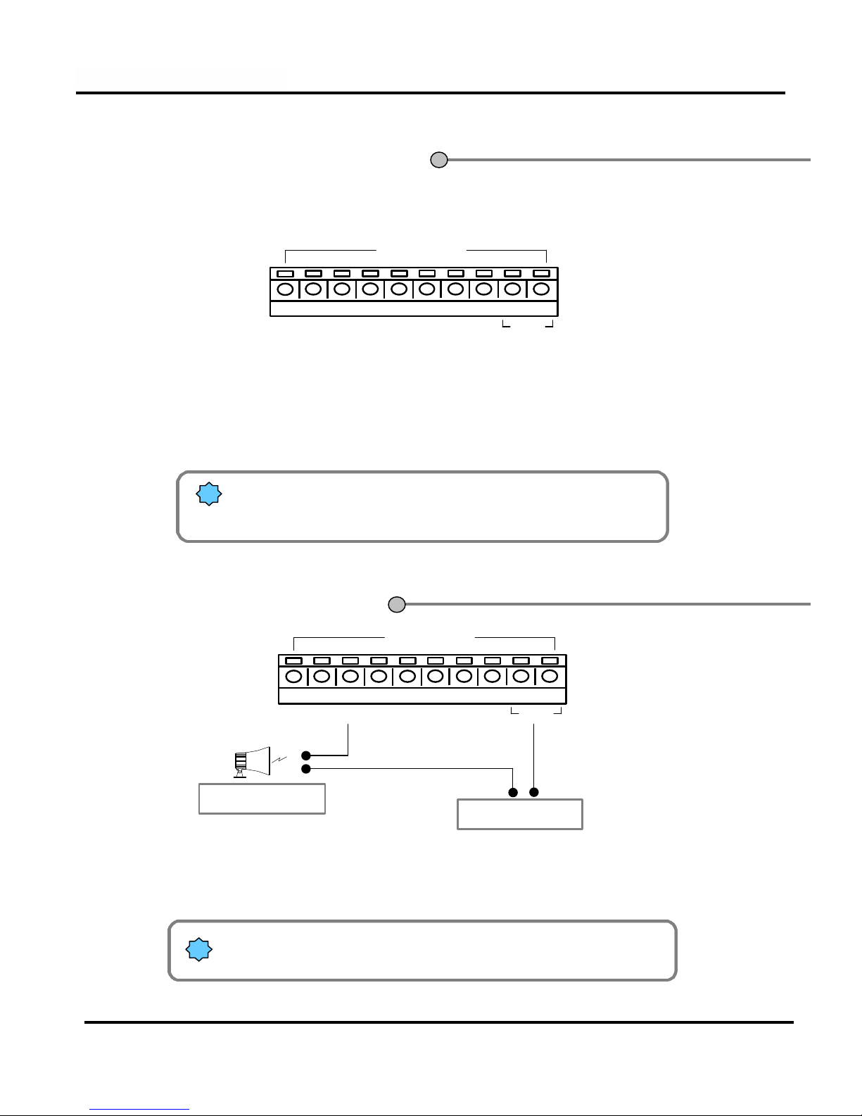
5. External Sensor(input)
5. External Sensor(input)
Connection
Connection
12345678COM
SENSOR
!Only dry contact output sensor should be used. Normally closed or
open contact are supported, selection is made in the software
For each sensor such as infrared detectors, heat sensors, magnetic contacts or switches,
one of the two conductors of the contact should be connected to one of the COM terminal.
The other conductor of the contact is connected to any of the sensor inputs (1-8) that you
have selected.
The control outputs are normally open contacts, they closes in response to an activation.
!The contacts are rated 12V and 300mA.
External relays should be used for heavier loads.
12345678COM
CONTROL
Power (DC 12V)
(-)
(+)
Alarm, Siren etc.
6. External Control
6. External Control
Connection
Connection

12
DVR Manual version 4.020 Nov. 22, 2001 rev.2
1.1 Display mode 13
1.2 Password setting 14
1.3 Hardware setup 15
1.4 Motion detection setup 19
1.5 Schedule setup 23
1.6 Screen split setup 25
1.7 Communication setup 26
1.8 Site Information 31
1.9 Password setup 33
1.10 Audio setup 34
1.11 System setup 35
Motion Tracking (future option)
1.12 Storage setup 36
1.13 E-Map 37
1. Configuring the Program
2. Software User Guide

13
DVR Manual version 4.020 Nov. 22, 2001 rev.2
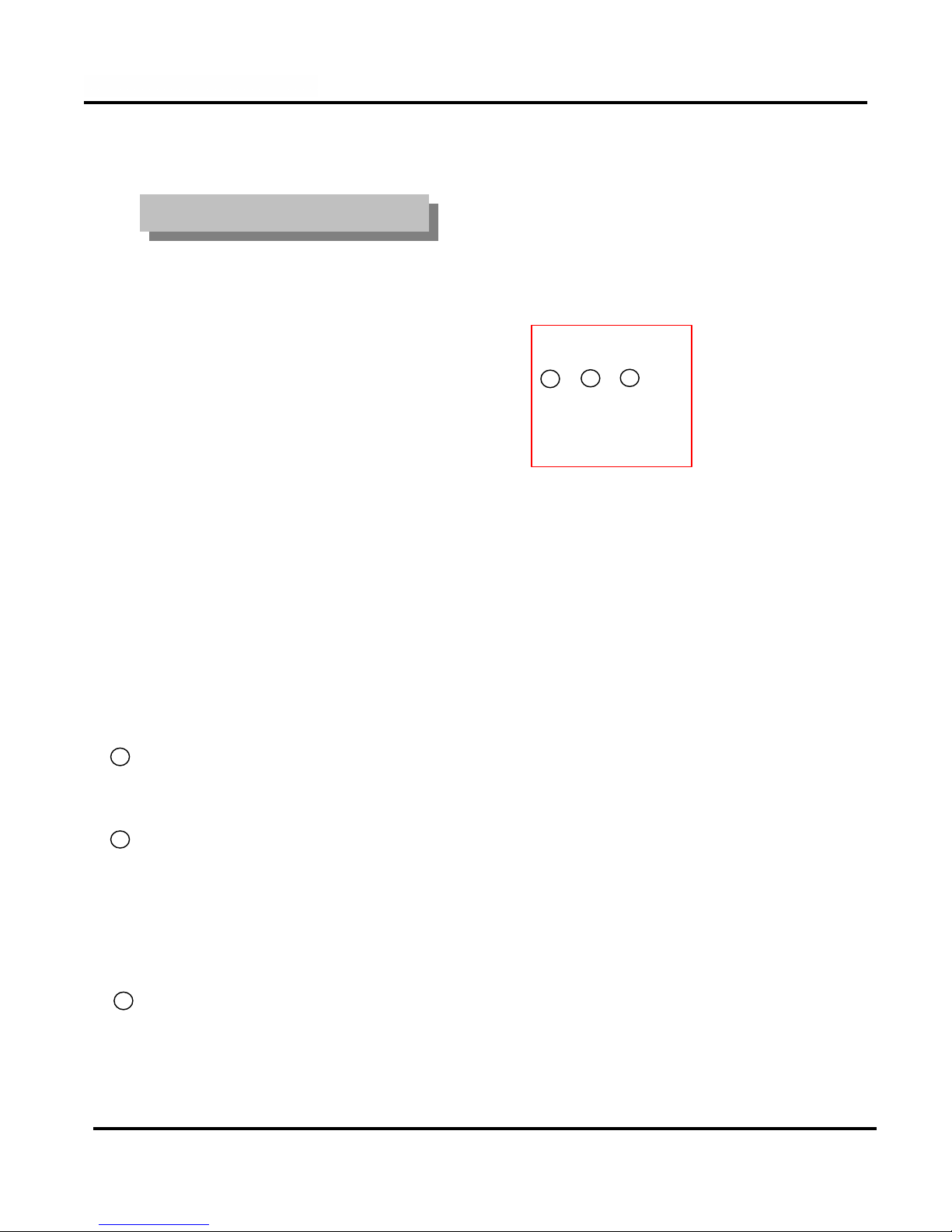
1.1 Display Mode
1.1 Display Mode
(default)
(default)
Display present date and time
3
[Search]
•Switches to the search screen to view stored images
4
[Setup]
•Switches to Set up screen to allow the configuration of system environment and functions
5
[Selecting split screen]
•Select the screen layout you wish to view.
•1,4,6,9,10,13,16 or full screen mode is available
•converts multi-screen to quad sequence screen
Recording status of each camera : Red ‘Rec’for continuous recording;
Blue ‘MREC’for motion-detection recording
none for not recording
1
2
6
[Quit]
•Exit the program (and shutdowns the computer)
7
Display the recording status of the cameras and the status of Sensors and Controlsl
1
4
5
6
7
2
3

14
DVR Manual version 4.020 Nov. 22, 2001 rev.2
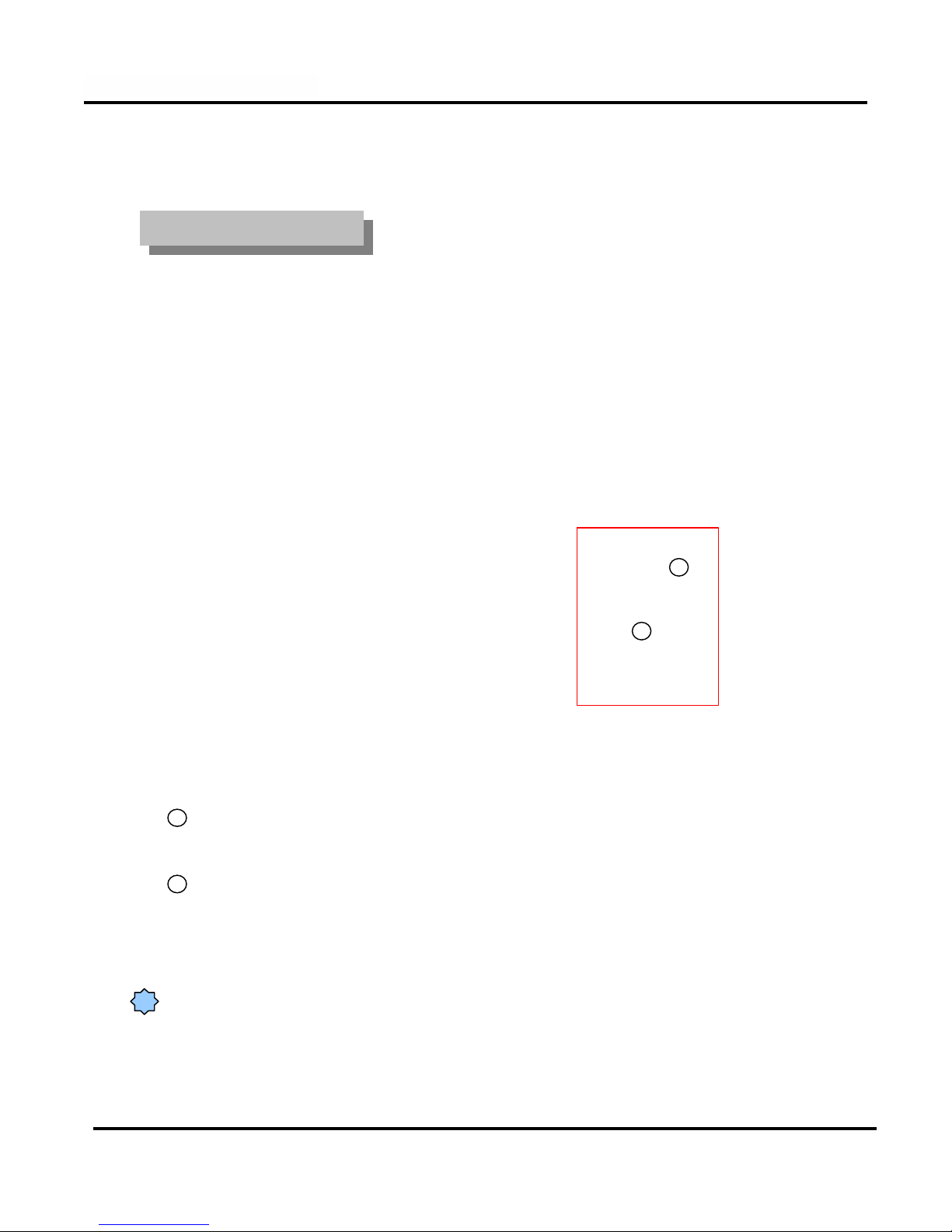
1.2 Password setting
1.2 Password setting
1[Menu]
Click the button
Default screen(display mode)
2Password input window appears. Access to the
setup functions is protected by up to three
password levels
You can enter setup menu by entering a 4-digit password (see password configuration).
You cannot change a password without knowing the older one. So be sure to memorize it.
We recommend that user 1 handles all the passwords.
There is one password by configurable security level.
How to set up
How to set up
When you use the system for the first time
there is no set password, just click “OK”. See
password setup
3
1
!
!
!
!

15
DVR Manual version 4.020 Nov. 22, 2001 rev.2
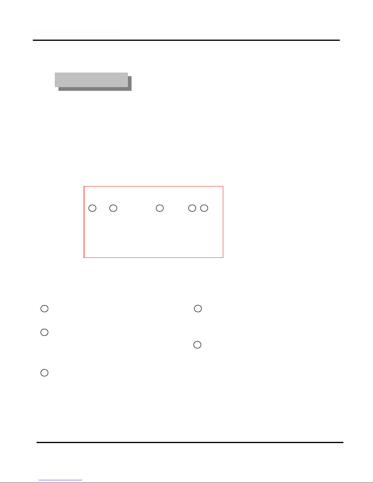
1.3 Hardware setup
1.3 Hardware setup
[Name]
•Type the camera name,
Ex.: Parking lot, Main Entrance, etc.
•You can type up to 14 characters.
[Sensor]
•You can attach up to 8 external sensors.
•If the related external sensor is activated,
the recording of the camera will be initiated.
•If more then one sensor is associated to a camera
separate each entry with a comma.
[Use]
•Click the check box of the cameras to be enabled.
1
[Type]
•Select the type of Pan/Tilt or speed dome from the
list of supported models.
2
3
[P/T]
•Click if the camera is equipped with a PTZ or
speed dome.
4
5
Camera setup
Camera setup
123 4 5
6
[Motion]
•Future option
6
Always save the setups before changing to other configuration TAB or exiting the configuration menus.
!
16
DVR Manual version 4.020 Nov. 22, 2001 rev.2
External Sensor Setup
External Sensor Setup
[Use]
•Sensor enable, the check box of every desired sensor must but checked.
[NC/NO]
•Choose type of sensor
•Clicking the button will toggle between [NC] and [NO]
([NC] is the default setting)
•NC : Normal Close Type Sensor
•NO : Normal Open Type Sensor
1
2
3[Use Alarm/Not use alarm]
Select <Use alarm> if an audible alarm is desired on sensor activation from DVR (PC speaker sound)
Select <Not use alarm> for a silent alarm.
12 3
17
DVR Manual version 4.020 Nov. 22, 2001 rev.2
Control Setup
Control Setup
[Setup]
•Check to enable a control output.
1
[Name]
•Enter a name for the control
•Can be up to 14 characters
Ex.: Siren, lamp, or alarming lamp
2
3
4[Sensor]
•Select which sensor will activate the control.
5[Working sec.]
•Enter the time the output will be activated in sec.
(The maximum is 3600 sec and default is set to 0 sec)
[Auto ON/OFF time]
Specify the time frame in which the sensor is
operational. Outside the time specified interval, the
control is disable.
By default, the time frame specified (00:00~24:00)
enable the sensors 24 hours a day.
1 2 3 4 5
18
DVR Manual version 4.020 Nov. 22, 2001 rev.2
External Monitor
External Monitor
[[Select time(sec)]
Sets the sequence dwell time for the spot (Call) monitor, the time selected is in seconds.
1
You can use a TV with video input or a standard CCTV monitor as external monitor.
[Camera 1~16]
Select the camera to enabled for display on the spot (call) monitor sequence.
2
1
2
!An RCA to BNC adapter is required to connect a standard CCTV monitor to the external monitor output.

19
DVR Manual version 4.020 Nov. 22, 2001 rev.2
1.4 Motion Detection setup
1.4 Motion Detection setup
This function enables you to record any activity without the need for external sensor.
[Camera]
Select the camera to be configured
1
[Detection Area]
To assign a detection area, place the mouse cursor
over the desired area, drag it until your desired area is
fully covered. You can designate up to 5 different
detection areas for each camera.
To delete an area click the area to be deleted and drag
it out of the display area.
2
[Area clear]
Clears all detection areas for the selected camera.
3
[Area draw]
Selects the entire screen as a detection area for the
selected camera..
4
[Sensitivity :Less -- more]
Is used to adjust the threshold point of the motion
detection. This allow the motion detection to be
more or less sensitive to activities in the selected
areas.
5
15
6
34
2
[Individual camera Adjustment]
•Is used to adjusts the brightness, color and
contrast of each camera.
•The color button is used to select the type of
camera used. It toggles between monochrome
and color.
[Default Value]
•Will bring back the factory default values.
8
7
[Alarm (M)]
When selected, it enables an audible alarm from the
DVR when motion is detected.
[Alarm time interval]
Specify the time frame in which the motion alarm is
operational. Outside the time specified interval the
motion detection alarm is disable.
By default, the time frame specified (00:00~24:00)
enable the motion detection alarm 24 hours a day.
6
7
8
Table of contents


