Brigade Electronics MDR-304A User manual

MDR-304A
Digital Video Recorder
Instruction Manual
Stock code: 2919A
1
SAFETY PRECAUTIONS
All the following safety and operation instructions which will prevent harm or damage to the operator or
other persons should be read before the unit is operated.
INFORMATION
This equipment has been tested and found to comply with the limits for a Class A digital device,
pursuant to Part 15 of the FCC Rules. These limits are designed to provide reasonable protection
against harmful interference when the equipment is operated in a commercial environment. This
equipment generates, uses, and can radiate radio frequency energy and, if not installed and used
in accordance with the instruction manual, may cause harmful interference to radio
communications.
Operation of this equipment in a residential area is likely to cause harmful interference in which case
the user will be required to correct the interference at his own expense.
WARNING
To reduce the risk of fire or electric shock, do not expose this appliance to rain or moisture.
Do not block ventilation openings.
Do not place anything on top of the unit that might spill or fall into it.
Do not attempt to service this unit yourself as opening or removing covers may expose you to
dangerous voltage or other hazards. Please refer all servicing to qualified service personnel.
Do not use liquid cleaners or aerosols for cleaning.
This installation should be made by a qualified service person and should conform to all local
codes.
To prevent fire or electric shock, do not overload wall outlets or extension cords.
This unit must be grounded to reduce the risk of electric shock hazard.
!
!
!
!
!
!
CAUTION
Danger of explosion if battery( RTC Battery ) is incorrectly replaced. Replace only with the
same or equivalent type recommended by the manufacturer. Dispose of used batteries
according to the manufacturer’s instructions.
Risk of explosion if replaced by an incorrect type. Dispose of used batteries according to the
instructions.
!
!

2
1. INTRODUCTION .....................................3
Product Features............................................3
Accessories....................................................4
Front View ......................................................6
Rear View.......................................................8
MCU Rear View .............................................9
Power Delay Connection .............................10
The Power Connector ..................................11
I/O Port.........................................................13
I/O Connection .............................................14
Voltage Management ...................................15
2. INSTALLATION .....................................16
System Information and Channel Selection.16
System information ......................................16
Channel Selection........................................17
Updating System Software ..........................17
The G-sensor ...............................................17
3. SET UP................................................18
Configuring Recording Settings ...................18
Alarm Recording ..........................................19
Externally Triggered Recording....................19
Menu ............................................................19
REC Setting .................................................20
Alarm............................................................21
CLOCK/ TITLE Settings ...............................23
COMMUNICATION Settings ........................23
DISK Settings...............................................24
SYSTEM Settings ........................................24
Alarm and Motion Settings...........................26
4. OPERATIONS .....................................27
Recording.....................................................27
Manual Recording ....................................... 27
Playback Operations ................................... 27
Normal Playback ......................................... 27
Fast Forward/Backward .............................. 27
Slow Forward/Reverse................................ 27
Play back picture-by-picture........................ 28
Search Operations ...................................... 28
FULL LIST Search....................................... 28
ALARM LIST Search ................................... 28
TIME Search ............................................... 28
THUMBNAIL Search ................................... 29
Backup Operations...................................... 30
SD Card Backup Operations....................... 30
Key Lock Operation..................................... 31
5. MISCELLANEOUS ................................ 32
System Default ............................................ 32
O.S.D Messages ......................................... 33
Time Index Table ......................................... 34
Specifications .............................................. 35
HDD Viewer............................................... 36
Introduction.................................................. 36
Installation Instructions - Software .............. 37
Installation Instructions - Hardware............. 40
Basic Operation........................................... 40
Advanced Operation.................................. 43
Save a snapshot to a PC ............................ 43
Save a video file to a PC............................. 43
Read the CSV report................................... 44
APPENDIX 1. –Table of LOG Message..... 46

3
1. INTRODUCTION
Product Features
Quad-based operation: real-time operation and playback (30 FPS/ per channel).
MPEG4 compression with resolution up to 720X480 (NTSC) / 720X576 (PAL).
4x Elite/Extreme connectors for AV inputs.
4 camera audio inputs, 2 auxiliary audio inputs, 1 audio output (1 channel record).
Pre-alarm image recording.
USB interface showing video records on a Laptop/PC.
GPIO: 4 inputs and 2 outputs.
Operating temperature: 0℃to 50℃.
Time-lapse and real-time recording.
Refresh rate up to 30 IPS (25 IPS for PAL).
Image quality selectable at 4 different levels for recording.
Alarm recording mode.
Quick search by time, alarm, event, and recording list.
Fast and slow playback of video recorded at various speeds.
Single-picture playback.
On-screen setup menu, title and system timer.
Password protection.
Disk-full warning.
Operation-status record log.
Automatic detection of voltage.
Built-in SD card slot for copying images to an SD card.
Watermark.
Window Division.
Vibration and mechanical shock protection.
By taking advantage of the optional G-Sensor, the MDR-304A will register and record X, Y & Z impact
data in the event of an accident and can be used as an alarm trigger.
If the voltage is less than 10.4/17.5 volts, the MDR-304A recorder will display a message “Low Voltage”
and then automatically power off after beeping for 3 -5 seconds.

4
Accessories
The kit contains the following items:
Sub-System
Qty
Sub-system Description
1
MCU-304A-XXX (Mobile Caddy Unit)
1
MDR-304A-DS (Docking Station)
(2798A)
1
AVM-304 (Anti-Shock/Vibration
Mounting)
(2917)
1
MDR-304A-MAN (Instruction Manual)
(2919A)
1
CD-304A-01 (Installation CD)
(2920A)
1
PV-12 (12V MCU Power Supply)
(3973)
1
MDR-304A-PC (Power Cable)
(3972)
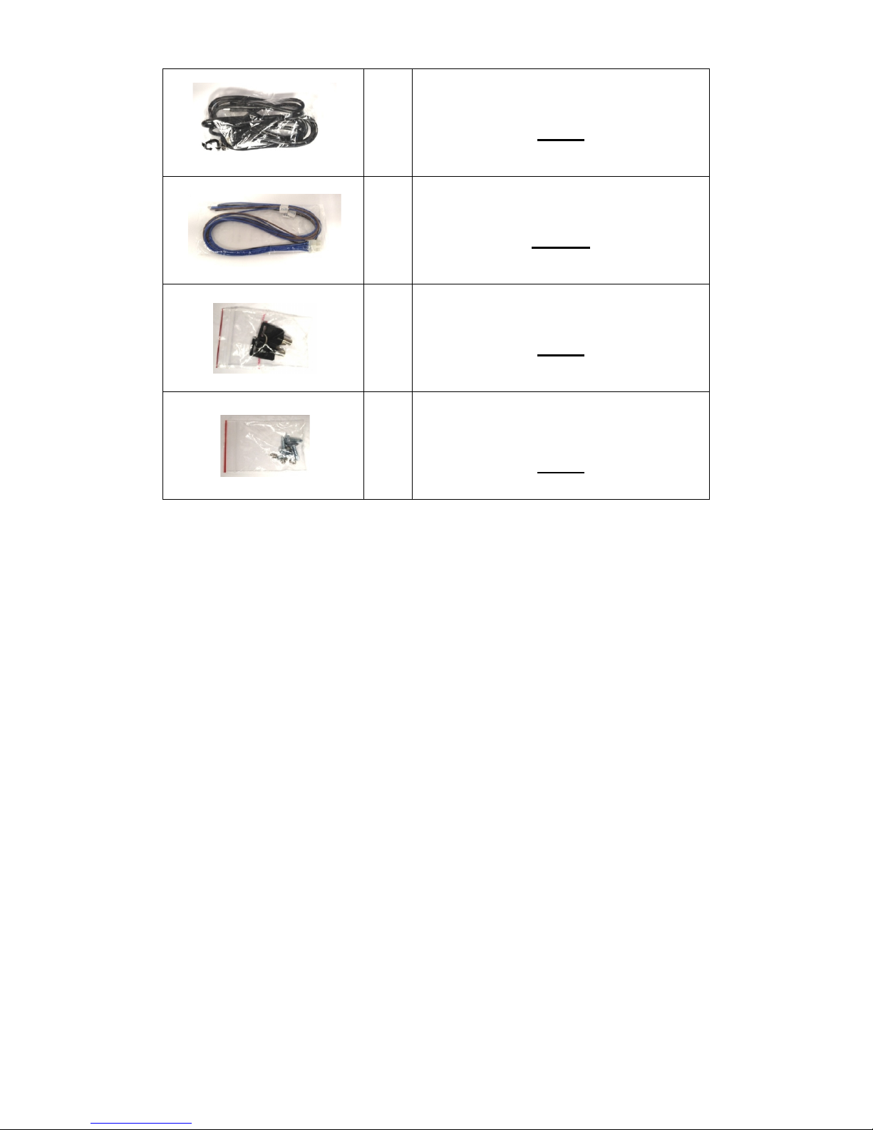
5
1
USB-001 (USB Lead)
(2918)
1
MDR-304A-TRIG (Trigger Cable)
(2997A)
1
MDR-304-SK (2x Security Keys)
(2994)
1
MDR-304-STS (4x Self Tapping
Screws)
(2995)
Notes: The MDR-304A should not be operated without the anti-shock/vibration mounting unit.
Stock codes that are underlined are not available separately.
6
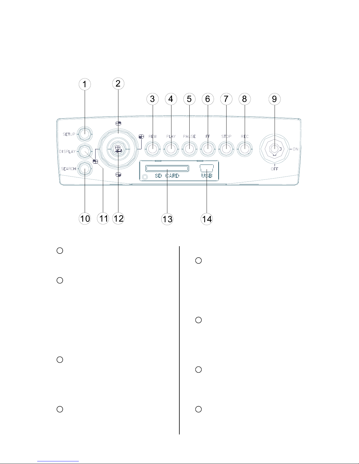
Front View
SETUP button:
Press this to enter the setup menu. Press
again to exit the setup mode.
Left/ Right/ Up/ Down (CH1/CH2/ CH4/
CH3) buttons:
In the menu setup mode / search mode,
press the four buttons on the dial to
highlight desired items in the menu
setup mode. In the live / play mode,
press the four buttons on the dial to
select a channel for display.
REW button:
Press this to play a recorded video in the
reverse direction at a speed that's faster
or slower than the recorded speed in the
play mode.
PLAY button:
Press to play back a recorded video from
the hard disk. (A light glows red in the
PLAY mode.)
PAUSE button:
In a playback display, press this to
freeze the display. During the freeze,
press to display one frame of a picture at
a time in the forward direction (A light
glows red in the PAUSE mode.)
FF button:
Press this to play a recorded video in the
forward direction at a speed that's faster
or slower than the recorded speed in the
play mode
STOP button:
Press to stop playing back a recorded
video. (A light glows red in the STOP
mode.)
REC button:
Push to start recording video into a hard
disk while in the live display mode. (A light
1
2
3
4
5
6
7
8

7
glows red in the REC mode.)
MCU Lock:
This key lock secures the MCU with the
hard disk in place. When you lock it in, it
powers on the device. When you unlock
this key and take out the inner case, the
power turns off automatically.
SEARCH button:
Press to enter the search mode to
access the recorded video.
DISPLAY button:
Press to show the system operation
status on the screen.
Enter / (Quad) button:
Press to enter a selected item and save
the setting in the menu setup mode. In
the live/ play mode, use this button to
show a quad display.
SD CARD slot:
This is used for system software
updating, saving and loading of user
settings as well as the saving of JPEG
still images or short AVI clips.
USB port:
Allows the recorder to be
connected to a PC or laptop for
viewing of recorded files using
HDD Viewer Software.
Also can be used to quickly
transfer larger quiantities of raw
video data for storage onto a PC or
laptop Hard Disc when converted
to FAT32 format. HDD viewer
software is still needed to view
these files.
9
10
11
12
13
14
8
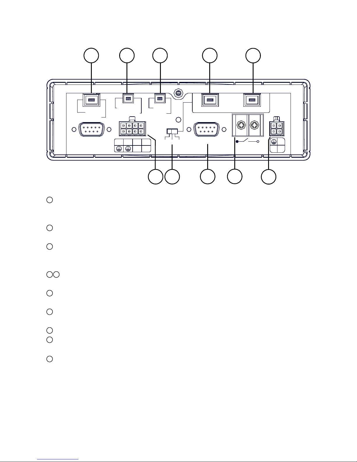
Rear View
GPS & Remote Controller Connector:
The left side connector links up with the optional GPS receiver to capture local position information
data. The right side connector links up with the optional remote controller.
Audio Out / Video Out:
Main output for connecting to an LCD monitor, or any display with Audio & Composite Video inputs.
AUX 1 / AUX 2:
Individual line level inputs for external audio sources. Only one of these inputs can be selected at a
time. Note that are line level inputs and may not be suitable for low level microphones.
Camera In:
Combined video and audio inputs. These connectors also deliver supply voltage to the camera.
I / O port:
Input and output port for connecting to external devices.
Voltage Selector Switch: Please select the required output voltage according to the camera
specification. There is a choice of 6V, 9V or 12V. (12V Should be used for Brigade cameras)
G Sensor port:For the connecting of an optional G Sensor.
Power Delay:
For delaying the powering up of other vehicle devices.
Power Input:
For connecting to either a 12V or 24V supply (These should be fused suitably).
1
2
3
4
5
6
7
8
9
10
+24V
+12V ACC
Power Delay
30A MAX
G-SENSOR
12V 9V 6V
I/O
OUT1 OUT2
IN1 IN2 IN3 IN4
RS-232
GPS
Remote
Audio Out
Video Out
AUX1
AUX2
1234
Camera In
12 3 45
76 8910
9
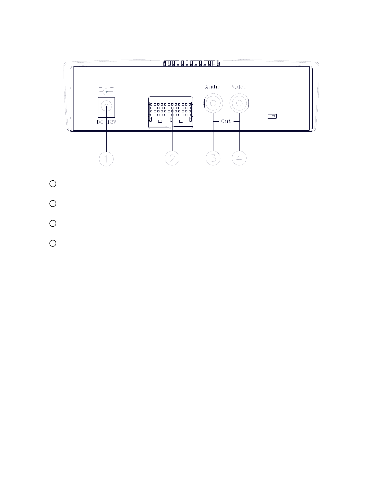
MCU Rear View
Plug Inlet:
The inlet connects to an external power supply. Connect to 12V DC UL Listed Class 2 Power Supply.
Hard Metric Connector (Male):
This connector links up with the outer casing.
Audio Connector:
Line level audio output for when the host is powered independent of the outer case.
Video Connector:
Composite video output for when the host is powered independent of the outer case.
1
2
3
4
Table of contents


