Premier Hazard DVR208 SERIES User manual

User Manual
For
DVR208 MDVR SERIES
Mobile Digital Video Recorder

Notice
The information in this manual was current when published. The manufacturer reserves the right to
revise and improve its products. All specifications are therefore subject to change without any notice.
The purpose of this manual is to kindly aid the user for the operation for our MDVR. The user should
have a basic understanding of computer operation and basic knowledge of how to connect peripherals
and make some settings.
Copyright
Under copyright laws, the content of this manual may not be copied, photocopied, reproduced,
translated or reduced to any electronic medium or machine- readable form, in whole or in part, without
prior written consent of Premier Hazard.

1
Guarantee & Warnings
1) Electrical Apparatus Safety
All installation and operation should comply with local electrical safety norms.
2)
Transportation
In the process of transportation, storage and installation, please avoid crushing, violent vibration,
impact and water ingress, allow space for air to circulation around MDVR.
3)
Installation
Ensure installation is carried out by trained / competant installation technicians.
4)
Requirements on Engineers & Technicians
All checking and maintenance should be done by qualified technicians and engineers. We do not
undertake any responsibility caused by unauthorized modifications.
5)
Requirements on fitting location
The equipment should be installed and stored in a cool and dry place, away from direct sunlight,
flammable or explosive substances, etc. Keep gaps not less than 3cm around the device to facilitate
ventilation for cooling.
6)
Accessories
Only use accessories supplied by Premier Hazard. Insulate circuit ground and metal
shell for all the peripherals.
Before installation, please open the package and ensure that all parts are included. If
there are any problems, please contact us as soon as possible.

2
Contents
1. PRODUCT CHARACTERISTICS...................................................................................................................... 3
1.1. OVERVIEW.........................................................................................................................................3
1.2. FEATURES......................................................................................................................................... 3
1.3. FUNCTIONS.......................................................................................................................................3
1.4. SPECIFICATIONS............................................................................................................................. 4
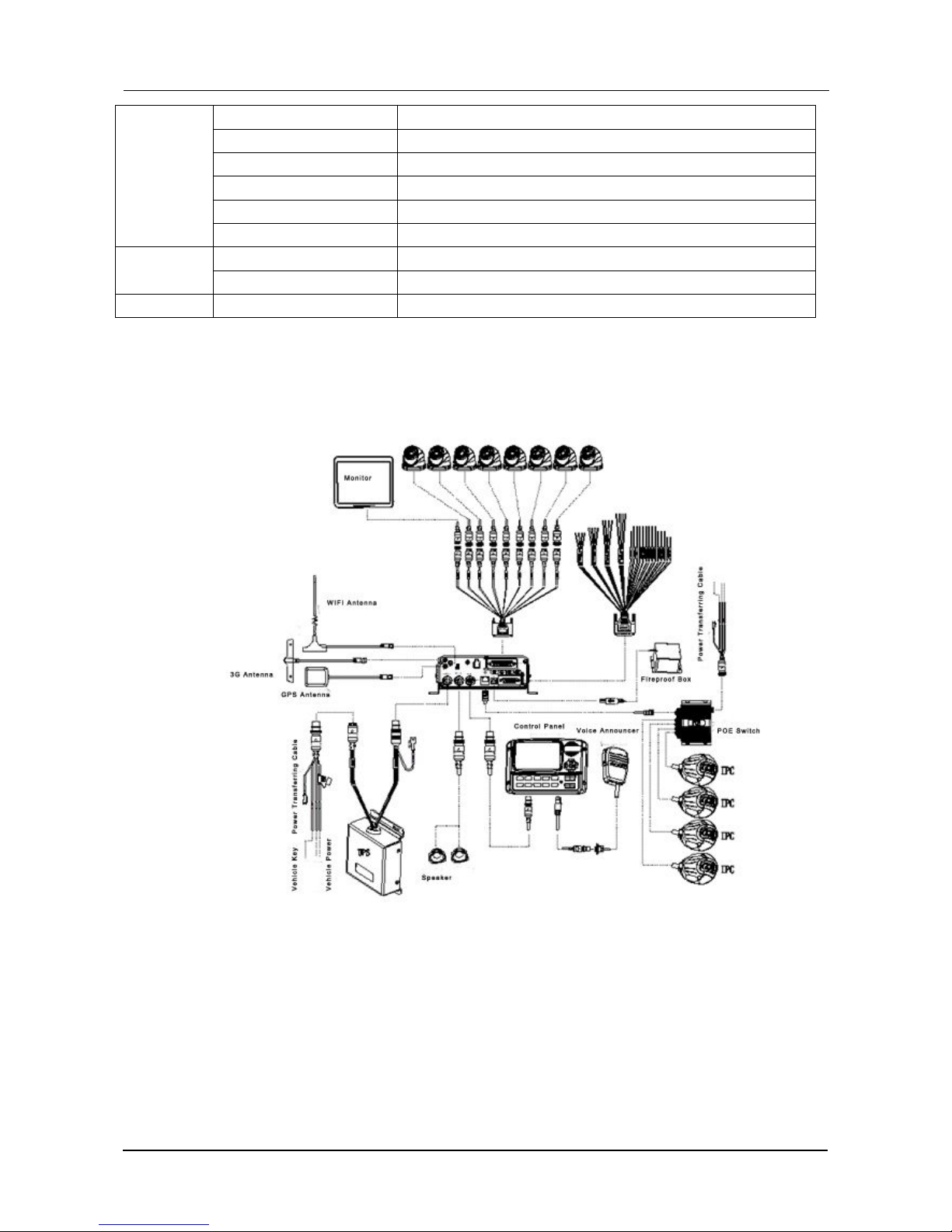
1.5. SYSTEM DIAGRAM..........................................................................................................................5
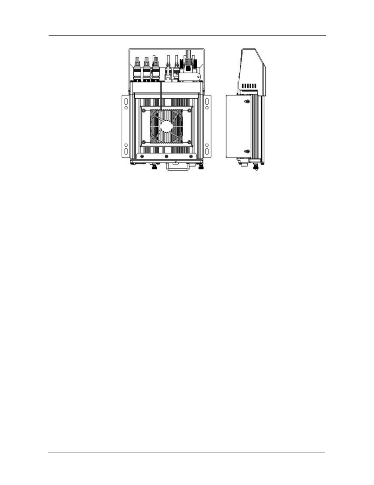
1.6. EXTERNAL INTERFACE................................................................................................................. 6
2. SETTING..............................................................................................................................................................8
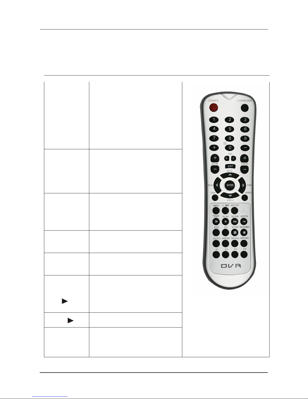
2.1. REMOTE CONTROL PANEL.......................................................................................................... 8
2.2.
CP163-003 CONTROL PANEL.......................................................................................................9
3. OPERATING INSTRUCTIONS........................................................................................................................ 10
3.1. LOCAL LOGIN..................................................................................................................................10
3.2. RECORD SEARCH AND EXPORT:............................................................................................. 12
3.3. LOG SEARCH AND EXPORT.......................................................................................................14
3.4. SYSTEM STATUS........................................................................................................................... 16
3.5. BASIC SETUP..................................................................................................................................17
3.5.1. REGISTER INFOMATION (SETUP VEHICLE INFORMATION).....................................17
3.5.2. TIME SETUP............................................................................................................................ 18
3.5.3. START UP.................................................................................................................................19
3.5.4. USER SETTING...................................................................................................................... 20
3.5.5. NETWORK SETTINGS.......................................................................................................... 22
4. VIDEO SURVEILLANCE.................................................................................................................................24
4.1. REAL-TIME SURVEILLANCE....................................................................................................... 24
4.2. RECORD...........................................................................................................................................26
4.3. IPC SETUP....................................................................................................................................... 28
4.4. DATA COLLECTION........................................................................................................................29
4.5. ALARM.............................................................................................................................................. 30
4.6. MAINTENANCE............................................................................................................................... 32
4.6.1. CONFIGURATION...................................................................................................................32
4.6.2. DATA EXPORT.........................................................................................................................33
4.6.3. UPGRADE................................................................................................................................ 33
4.6.4. STORAGE.................................................................................................................................34
4.6.5. DEFAULT.................................................................................................................................. 34
5. REFERENCE APPENDIX.................................................................................................................................35
5.1. STORAGE CAPACITY CALCULATION.......................................................................................35
5.2. FREQUENTLY ASKED QUESTIONS.......................................................................................... 36

3
1. PRODUCT CHARACTERISTICS
1.1. OVERVIEW
DVR208 is an advanced and function-extensive Mobile Video Recorder specially designed for
network high definition, analog audio & video input. It uses high-speed processor and an
embedded operating system, combining with H. 264 video compression / decompression technology,
network technology and GPS locating technology. It can realize 720P high definition, CIF, HD1, D1,
WD1 video recording and vehicle driving information recording, as well as wireless data upload (Model
DVR208-002). With center software it also achieves alarm linkage central monitoring, remote
management and playback analysis. It is powerful with modular design, flexible installation, easy
maintenance and high reliability.
1.2. FEATURES
1)
All the modules are connected with secure connectors, supporting quick disconnection,
which is safe and easy to maintain.
2)
The MDVR will alarm automatically when a module fault has occured.
3)
4)
Combines physical, electrical and software anti-vibration
5)
Supports DC6~36V wide voltage input; suitable for 12V and 24V vehicle.
6)
Adapts dynamic coding technology to adjust the change of 3G network and ensure the fluency
of monitoring video.
Watermark technology: prevent data tampering and guarantee the video authenticity and legal
efficiency.
1.3. FUNCTIONS
1) Local recording and video playback: D1/HD1/CIF resolution optional.
2) Driving recording: provide statistics on speed, turning, brake, reverse, opening door, etc.
3)
Network function: support break point uploading continually, which can realize the remote
video surveillance, video download, remote alarming and network timing of the equipment,
network setting and remote upgrade, etc.
4) High-speed backup: support high-speed backup through USB2.0, as well as backup through
SD card.
5) User log: on-off status of the device, video loss, recording start time / end time, user log in / log
out, modification of the device parameters, timing, bus stop announcement and GPS status.
6)
Import and export of the configuration file: U disk import / export device parameters.
7) Device upgrade: support local and remote upgrade.
8) Alarm linkage: support linkage switch value output, image display, etc.
9) Storage formatting: formatting device hard disk and external USB devices.

4
1.4. SPECIFICATIONS
Function Overview
Preview, Recording, Playback, Network, Locating
System
OS
Linux 3.0.8
Control Mode
CP4, Easy Check, IR Remote Control, Network
Video
Input
8channel WD1+4channel IPC(720P) or
4channel WD1+8channel IPC (720P)
Output
2 channels
Total Resource
(8 x 25)FPS WD1 @ PAL / (8 x 30)FPS WD1 @ NTSC +(4
x 30)FPS 720P or
(4 x 25)FPS WD1 @ PAL / (4 x 30)FPS WD1 @ NTSC +(8
x 30)FPS 720P
Video Signal Standard
Electrical level: 1Vpp Impedance: 75Ω NTSC/PAL Optional
Audio
Input
8channels(12 channels if connects with IPCX4)
Output
2channels
Audio Signal Standard
Electrical level: 2Vpp Input impedance: 4.7kΩ
Display
Display Split
1/4/9 Image display
OSD
GPS information, alarm, temperature, acceleration, voltage,
device information, software version, MCU version, network
status
Operation Interface
Semi-transparent GUI
Recording
Video/Audio
Compression
H.264/ADPCM
Image Resolution
Analog:
PAL:WD1(928X576), WHD1(928X288), WCIF(464X288),
D1(704X576), HD1(704x288), CIF(352x288);
NTSC:WD1(928X480), WHD1(928X240), WCIF(464X240),
D1(704x480), HD1(704x240), CIF(352x240);
Digital:
720P(1280X720);
Image Quality
8 Levels adjustable
Recording Mode
Manual/schedule/Alarm(sensor trigger,
speed, acceleration, video loss, temperature)
Pre-recording
0-60minutes
Post-recording
0-30 minutes
Mirror Recording
Yes
Playback
Playback Channel
1/4 channels by local playback
Search Mode
Date/time, channel, event
Network
3G/4G
EVDO/WCDMA/TDD-LTE/FDD-LTE
Locating
GPS
Location tracking, speed detection and time sync
Storage
Hard disk
Supports 2.5" hard disk up to2TB
Interface
USB
USB2.0 x 2
SD
SD x 1

5
RS232
RS232 X 2
RS485
RS485 X 2
Sensor
8 inputs, 2 outputs
Serial
G-sensor (Internal)
Speed
1 channel pulse speed detection
Interface
Interface (CP4) Optional
Power
Input
DC8-36V
Output
1A@12V,1A@5V
Others
Water Proof Rate
IP54
1.5. SYSTEM DIAGRAM
Diagram1 (POE Switch RJ45)

6
Diagram 2 ( POE Switch Aviation-din)
1.6. EXTERNAL INTERFACE
1) Dimension

7

8
2. SETTING
2.1. REMOTE CONTROL PANEL
Remote control key directions
ON/OFF
1)when the password is turned off,
in preview screen, press this
bottom standby (soft start key),
press again the device turn on.
2)When the password is enabled,
in preview screen, press this key,
the password prompt box
appears, enter the administrator
password to restart the machine
(soft-start key).
LOGIN/LOCK
When the device has password
and press Login / Lock key to enter
the password.Because the system
does not recover and reset the
password function,please remember
the password.
ADJUSTMENT
Brightness, contrast, color, hue
are adjusted, in single screen,
with [+], [-] keys to adjust the user
can be independently adjusted for
each channel.
SETTING
Set menu key (when the password
is enabled, you can log on by using
this key)
BACK
Return to the previous submenu.
Eventually exit the setup menu and
exit to the monitor screen.
PAUSE/FRAME
OUTPUT
▍
Pause and frame output button
controls one frame with each
press during playback, press the
playback button to return to normal
playback speed.
PLAY
The play button starts playback.
SLOW PLAY
When the footage is playing,
pressing this button cycles playback
speeds 1/2, 1/4, 1/8 then returns to
normal playback speed.

9
FAST
FORWARD
Pressing the fast forward button
during playback image speeds up
by 2X, 4X, 8X playback speed
REWIND
Rewind button during plays back
image speeds by 2X,4X, 8X
STOP ■
Stop manual recording button
RECORD ●
Start manual recording button
DOWN ▼
During playback, turn the page /
next file
UP ▲
During playback, turn to previous /
previous document
PTZ
FUNCTION
Automatic, presets, called, zoom +,
zoom -, zoom +, zoom - iris +, Iris -
F1
Alarm Recording Export Shortcuts
F2
Start the PTZ function bottom
F3
Play bottom by time chosen
F4
Spare key
2.2. CP163-003 CONTROL PANEL
Repeat
Repeat station notification
Station
Notification
Station notification bottom
0-9
Number enter key
Confirmation
Confirmation key
Back
Back from the menu
Direction
Up / Down / Left / Right selection key

10
Operation Instrument
Remark:
When reporting to CMS server, use serial number.
When using Android pad, you need to select vehicle number, as when insert the wifi hot spot to USB port
of the 4120, the hot spot will get the vehicle number and change its SSID to vehicle number.
3. OPERATING INSTRUCTIONS
3.1. LOCAL LOGIN
When operating the device, user needs to have permission certified.
1) Press the remote control 【LOGIN / LOCK】or【SETUP】, the login screen will pop up.
2)
Right click the D-PAD, the shortcut menu will pop up, left click login picture, login screen will pop up.
3) Left click on the login button to login and right click to log out
Login Notice:
1) Software is automatically assigned by user name and password, it can be divided into user and
administrator privileges.
2) Password options can not be closed, but it can be set to null; when it is empty, user do not need to
enter the password to login。
Login interface Introduction:
User name:
1) Select users from the drop-down box. There are admin and user as defaults.
2) Currently, it can show two users and one admin.
Password:

11
1) User can enter the operation interface if entering the right password;
2)
Click cancel to exit the login interface;
Language:
1)
Support the language switch. "language" (Lang) means the current interface adopts English;
2) It will automatically switch once Selecting the language.
3)
Currently, it supports English and Chinese.
4) After switching languages, it will not restore language option when user restores the factory
Settings;
Default password and permission table is as follows::
Default Password
Related User
Related Authority
admin
admin
All Authorities
User
user
Search and playback
The password input Instruction:
1. If the password are numbers, user can enter it by remote control directly.
2.
User can click 【ENTER】 or the left click D-PAD on the remote control.
a. Move the cursor to the number position, press 【Enter 】or left click mouse button to select the
corresponding number.
b. Move the cursor to 【123】, press 【Enter】or mouse to choose input type, such as
the Numbers, letters, or special characters.
【ab】means lower case letters,【123】means numbers,【AB】means capital letters; the highlighted
place of background refers to the current cursor position.
c. Move Cursor to , Press【Enter】or left click mouse to move between the contents that have
entered.
d. Move Cursor to , Press 【Enter】or left click mouse to delete the previous input contents.
e. Move Cursor to , Press 【Enter】or the left click mouse to exit the keypad, the entered
contents will be written to the edit box.

12
f.
Move Cursor to【Esc】 position, Press【Enter】or the left click D-PAD to exit the keypad, the
entered contents will not be written to the edit box
3.2. RECORD SEARCH AND EXPORT:
Video search interface contains video file search, video data backup and video playback function.
When there is a hard disk or SD card, enter the video search interface. Following is the REC Search
interface:
In the calendar, the color below the dates means:
a. No color means no video.
b. Green means common video.
c. Red means alarm video.
d. Yellow means there are alarms and the video files are automatically lock (lock video).
Source: select the source of the video, there are main video, sub video and mirror video.
The main record means HDD record while sub record and mirror record are dual-stream records.
Select the date with record, click next, then enter the following interface:
Following is the record search detail and record search result interface:
Record search detail interface:
Record Type: User can choose all record, alarm record or normal record.
Channel choose:The channel is optional and mark with color that has record. The channel
with grey cannot be chosen if there is no record. As to different record type, it will show different
colour to which it relates.
Click search button in the record search detail page, user can enter then record search result page.

13
Time Bar: Time bar shows three time points, 0 o'clock, 12 o'clock, 24 o'clock. It shows what
type of videos during the time according to the marked channel.
Channel No: According to the situation of video for each channel video the day , the video will
be displayed on the time line. Tick the channel if user wants to playback the video.
Note: channel number is displayed from 1~20, please select page up/page down button to
change channel
Button description
Video playback: Choose the channel No., select start time to play < default start from 0 >, click
the playback button to playback the video.
In playback interface, user can choose fast forward or rewind, select the part of the video to view, the
button in the middle of screen can switch the channels. The image freezes and it will not exit
automatically when end of the recording is reached.
Time period settings: Click the time setting button, select start time and end time, it will backup or
playback the video in the selected time period. Click clip to export the video, the file format can
be.264< comprehensive file >, also can be.avi format.

14
Video export: Select the channel that has the video files, click this button, all the video files in
the effective time period will be exported to the external USB peripherals, file format can
be.264<comprehensive file >, also can be avi format.
User can also pull out the hard drive or SD card, export and playback the video by professional software.
3.3. LOG SEARCH AND EXPORT
In the log search interface, it records and displays all alarm events and login operation log. Enter the
"log query”, the interface will be shown as following :
Log Search interface instruction:
Calendar: the date with log will be marked on the calendar with green color.
Note: There is no color classification in the “log mark”, and all are green ones.

15
Log search interface instruction:
Start time: the start time for searching log files
End time: the end time for searching log files
Log types: classification of log search, including the operation log and alarm log and locking log
Operation log search interface instruction
Log includes the following information:
Log time: the time when event is triggered
Log name: event content
Supports page up/page down and export all log files of the specified date.
Do not support link to video file.
Log search
Alarm type: It includes all alarms, IO alarm , panic alarm and over speed alarm.
Log includes the following information:
Log time :the time when event is triggered
Log name:event content
Supports page up/page down and export all log files of the specified date.
Supports link to video file, click on button to playback video files
Lock log search
Log includes the following information:
Log time: the time of when event triggered.
Log name: event content
Log will be recorded according to channel number, each channel will have a lock log file.
Support page up and page down.
Can’t export all log files of the specified date.
Can link to video file, click on button to playback video files.
Unlock: Select log, and unlock it. Then the alarm log of lock will be cleared.
Note:
When lock the video file, system will record alarm log and lock log. The locked video file can only be
unlocked from alarm log.

16
3.4. SYSTEM STATUS
User can login the interface with no access restrictions.
System- Version information
System- Modules
System-Server status

17
System - Environment
System-Storage:
3.5. BASIC SETUP
Click setup button and enter the following interfaces:
3.5.1. REGISTER INFOMATION (SETUP VEHICLE INFORMATION)
Register information-Device info:

18
Register information- Vehicle info
Vehicle Number:When connected with PAD, the vehicle number is needed.
Vehicle plate:Input manually.
Line number:Input manually.
Register information—About the driver’s information:
Driver number: Input manually.
Driver name: Input manually.
3.5.2. TIME SETUP
Table of contents
Other Premier Hazard DVR manuals