The plastic Belt Guard (7676) must be
removed before the M19 can be turned
over manually. To remove the Belt Guard,
remove the Retaining Screw (G30163)
from the top of the Guard (on BST mod-
els only). Press on one side tab while
prying out the locking face, at the top of
the Guard. Next, pull down
slightly on the top of the Guard to release
the bottom tab. The Guard will now be
free to lift off from around the Belt Guard
(7675).
To reassemble, interlock the bottom
tab and pull up slightly on the Guard to
interlock the side tab, then squeeze the
two halves of the Guard together to
lock the remaining tab. Reassemble
the retaining screw at the top of the
Guard (on BST models only).
8
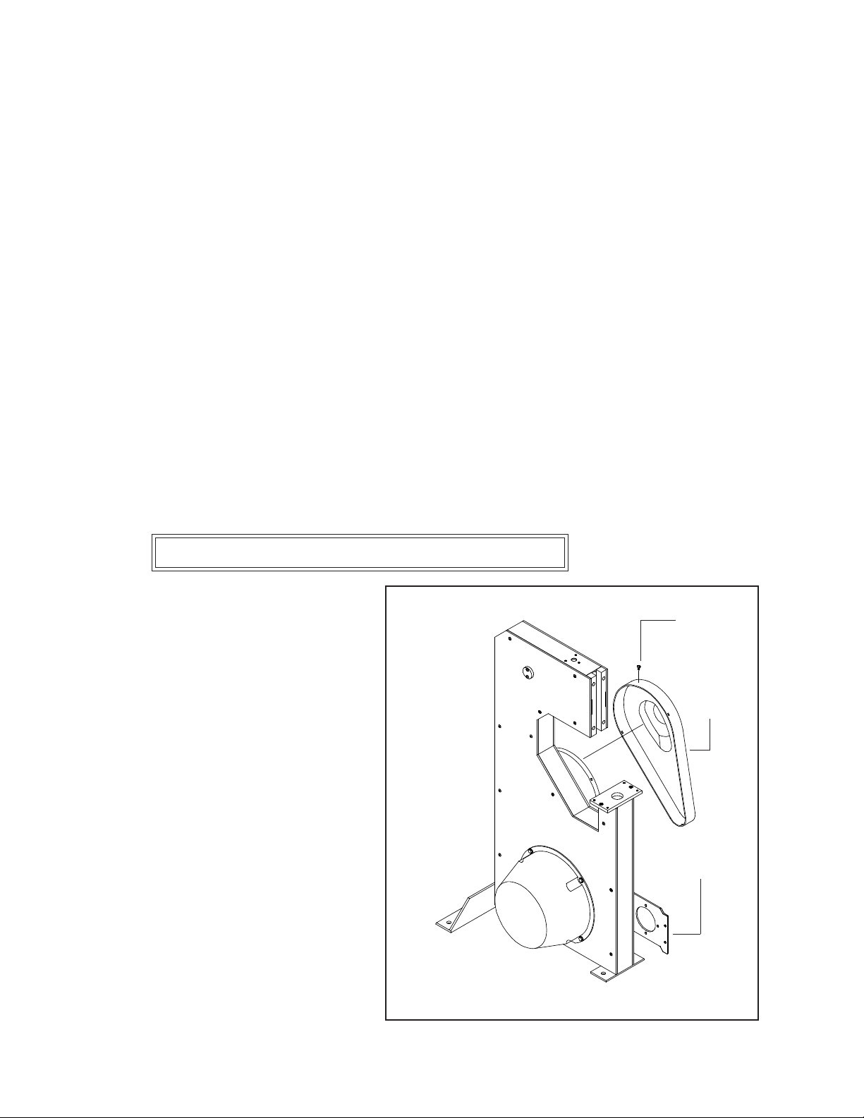
Belt Guard Removal and Assembly (Figure 2)
Figure 2 - Belt Guard Removal
7676
G30163
*BST Models Only
G30048
sure that the Flat Washer (PG10271) is between the Spool and the Wire Spool Bracket. Also verify that the
wire payoff is identical to the payoff in Figure 1; from left to right. Improper wire payoff will result in
poor stitching. Slip the Plastic Washer (M11009) over the Spool Stud and replace the Tension Spring and
Set Collar. Apply slight pressure on the Set Collar, pre-loading the Tension Spring, then tighten the Thumb
Screw in the Set Collar until secured. Mount the Wire Guide Spring (15150A or G20286A) in the Wire
Guide Spring Bracket (15154 or G20278AA). A properly set Tension Spring will cause the Wire Guide
Spring to flex but not actually hit the wire spool. The Tension Spring is designed to prevent the Wire Spool
from over-running and tangling.
Loosen the two (2) Set Screws (38) in the bottom of the Complete Table Assembly (K1033)andpull
the two (2) Pins (203B) in the Table out to each side. Center the Table Assembly over the Clincher
Mount Assembly and make sure the Table Support (7648) is under the pin on the Table Support Bracket
(7645A). Push the two (2) Pins from the Table into the Mount Assembly until they click. Tighten the
two (2) Set Screws to further secure the Table to the M19. Make sure the Table converts from the flat
to saddle position when the Table Support Bracket is activated.
The Work Guide (M7201B) can be attached to the Complete Table Assembly with two (2) Work Guide
Screws (63). The two (2) Work Stops (7423) can be secured to the Work Guide by tightening the two
(2) Thumb Screws (425).