10
feeding downward, turn the Eccentric clockwise.
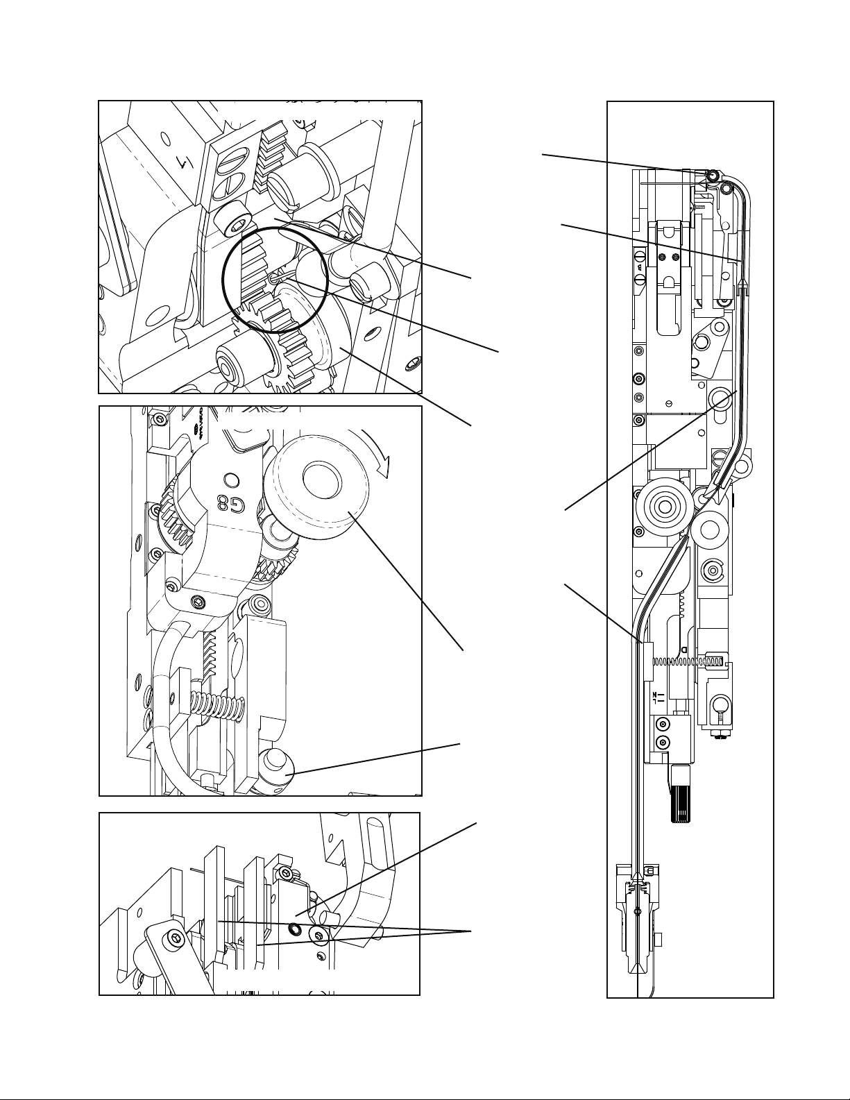
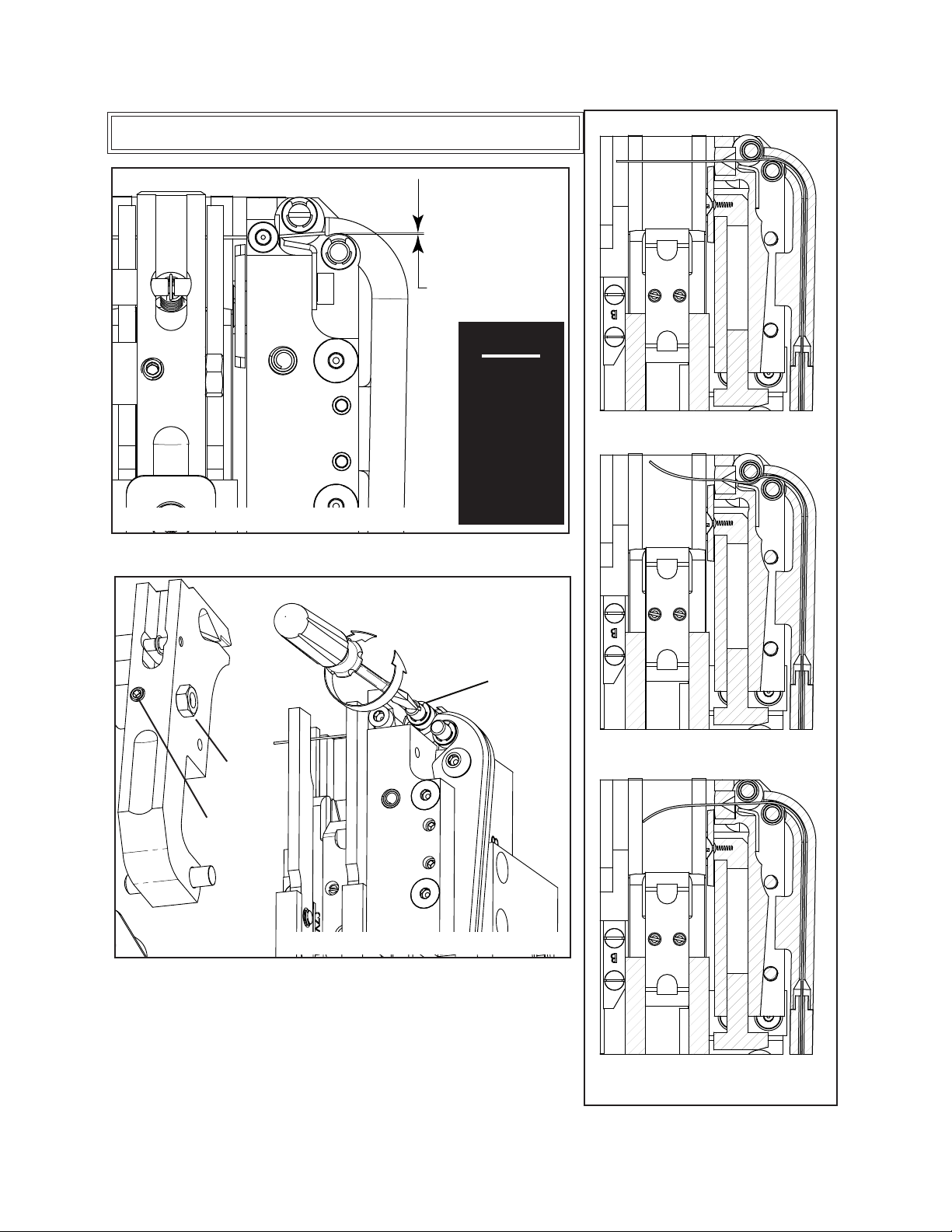
Front-to-Back Adjustment (APPLY ONLY UP TO LOT13)
If the Wire Guide Bars are not properly positioned, the wire
will rub against them as it exits the Cutter Block. Look at the
G8 Head from the side past both the Right and Left Wire Guide
Bars(Figure12).Makesurethereisaclearviewoftheopening
in the Fixed Wire Cutter from the side of the G8 Head. If there
isnot,loosentheFlatHeadMachineScrewssecuringtheWire
Guide Bars to the Pivot Block and move them out of the path of
the wire. Tighten the Screws after making sure the Wire Guide
Bars are even with each other. Replace the Wire Holder and re-
engage the Wire Holder Retaining Spring.
In order to form a quality stitch, the
Wire Holder has to be in alignment with
the Bender Bar. Specifically, the cut piece
of wire held in the Wire Holder has to line
up with the grooves in the Bender Bar.
Pooradjustmentmaycausebrokencrowns
or other poor stitching.
Aligning the Wire Holder (Figure 13a & b)
Figure 12 - Wire Guide Alignment
Fixed Wire
Cutter
Screw
(1 per side)
WIRE IN
WIRE
HOLDER
ALIGN TO
BENDER
BAR
GROOVE
Wire Holder
Adjustment Screw
Figure 13a - Wire Holder Alignment
WIRE
BETWEEN
BENDER
INSERT
GROOVES
Figure 13b - Wire Holder Alignment