8
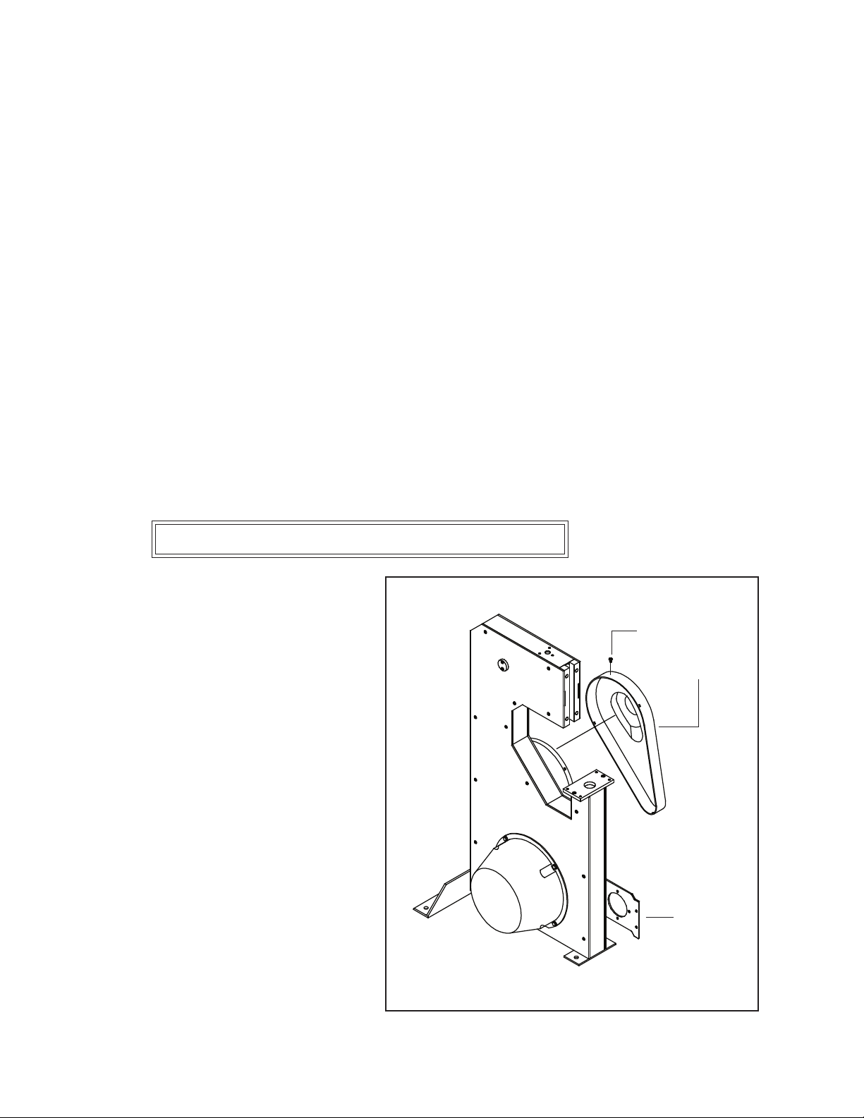
The plastic Belt Guard (7676) must be
removed before the M7 can be turned over
manually. To remove the Belt Guard,
remove the Retaining Screw (G30163)
from the top of the Guard (on International
models only). Press on one side tab while
prying out the locking face, at the top of
the Guard. Next, pull down slightly on
the top of the Guard to release the bottom
tab. The Guard will now be free to lift off
from around the Belt Guard (7675).
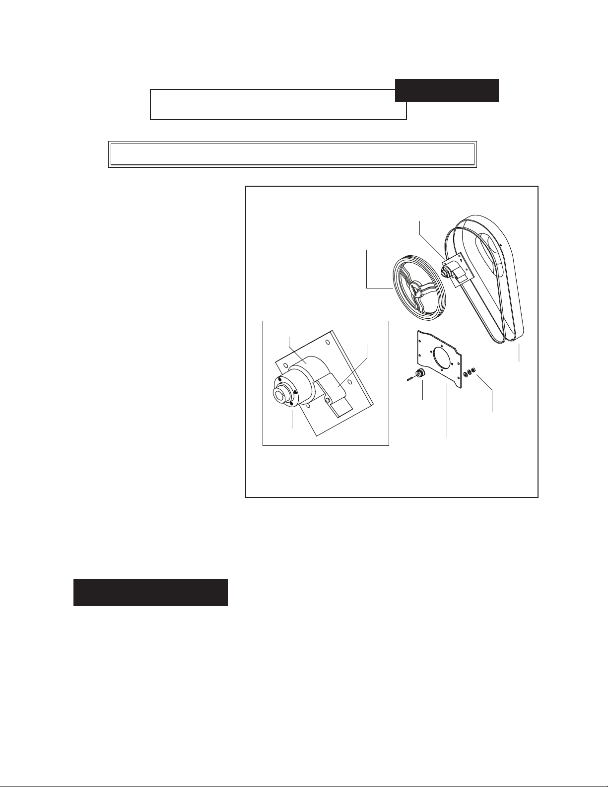
To reassemble, interlock the bottom
tab and pull up slightly on the Guard
to interlock the side tab, then squeeze
the two halves of the Guard together
to lock the remaining tab. Reassemble
the retaining screw at the top of the
Guard (on International models only).
Belt Guard Removal and Assembly (Figure 2)
Figure 2 - Belt Guard Removal
Insert the Wire Guide Spring (15150LA) into the top of the Wire Straightener Assembly. Loosen
the two (2) Set Screws (38) and remove the two (2) Work Table Swivel Pins (203B) from the Clincher
Mount Assembly (G30044A). Line up the holes on the underside of the Complete Table Assembly
(7656A) with those in the Clincher Mount Assembly and replace the Swivel Pins. Secure the Swivel
Pins by tightening the Set Screws in the Table Assembly. With the Table Assembly in the flat position,
mount the Work Guide (M7201B) with two (2) Thumb Screws (63). Slide the two (2) Work Stops
(7423) onto the Work Guide and tighten the Thumb Screws (425) to secure in the desired position.
Note: Do not allow the Work Guide to interfere with the stitcher head as this will cause damage to
both.
Electrical power is provided through the attached Power Cord (86243 or 86244) and should be con-
nected to an appropriate supply outlet but do not power on the machine until all safety checks have
been made. The machine has to be turned over manually to verify that the stitcher head is operating
freely before the M7 can be operated under power.
Note: Be sure to level the machine and secure it to the floor before use.
7676
G30163
G30048