DeLuxe Stitcher MiniStitcher HP User manual

Before using this Stitcher, all operators must study this manual and follow the safety warnings and
instructions. Keep these instructions with the Stitcher for future reference. If you have any questions,
contact your local DeLuxe Stitcher Representative or Distributor.
MiniStitcher HP
OPERATION AND MAINTENANCE MANUAL
IMSHP-A25.....StitchMaster....115 V....25 Wire
Machine Model : Serial Number :
Head Serial Number :
Date Purchased /Installed :
DELUXE
STITCHER
COMPANY INC.
®
ISP Stitching & Bindery Products
solving your wire stitching needs for 125 years...

0

MiniStitcher HP
Machine operators and others in the work area should always wear
safety glasses to prevent serious eye injury from
fasteners and flying debris when loading, operating,
or unloading this machine.
Do not operate this stitcher without all guards in place.
The stitcher will not operate without the front guard
closed properly. Do not modify the guards in any way.
Always disconnect the power supply before removing
any guards for servicing.
Never operate the machine with wire feeding through
the head unless there is stock above the clinchers,
otherwise serious damage may result.
Always turn power off when making adjustments. Always
disconnect the power cord before any disassembly work.
1
WARNING!

Introduction ......................................................................................................... 3
Specifications.....................................................................................................4
Installation .......................................................................................................5
Pre-Inspection ................................................................................5
Inspection ......................................................................................5
Set-Up ............................................................................................5
Assembly .......................................................................................6
Operation ........................................................................................................7
Wire Threading ..............................................................................7
Wire Straightening .........................................................................8
Adjustments and Settings ..............................................................9
Stitching Process .............................................................................................11
Solid vs. Moveable Clinching.........................................................11
Trip and Stitch Modes....................................................................12
Troubleshooting .............................................................................13
Maintenance......................................................................................................15
Lubrication ....................................................................................15
Cleaning ........................................................................................16
How to Order Spare Parts .............................................................16
Replacing Spare Parts...................................................................17
Modifications .....................................................................................................21
Timing ............................................................................................21
Appendices ......................................................................................................22
Exploded Drawings........................................................................22
Wiring Schematic...........................................................................40
Part Number/ Description Cross Reference ..................................41
Optional Equipment..........................................................................44
Registration Card .............................................................................48
Recommended Spare Parts.........................................................................49
Warranty .......................................................................................................50
Declaration of Conformity..............................................................................51
Table of Contents
2

The DeLuxe Stitcher MiniStitcher HP is a table-top version of the StitchMaster. A
completely portable stitcher, the MiniStitcher is ideal for closing padded envelopes,
carding, and blister packs.
The IMSHP-A25 which operates on 115VAC and conforms to all pertinent CE
standards. All other performance characteristics are the same.
The MiniStitcher comes standard with parts for 25 gauge or smaller round wire.
However, any MiniStitcher can be modified to accommodate any of the following wire
sizes: 23 or 24 gauge round or 21 x 25 flat. In addition, the MiniStitcher can be
ordered with these alternative wire size parts directly from your DeLuxe Stitcher
Graphic Arts Representative.
The MiniStitcher has a capacity up to 1/8” (3.2mm) or thirty sheets of 20 pound bond
paper with 25 gauge round wire and up to 1/8” (3.2mm) or thirty sheets of 20 pound
bond paper with 21x25 flat wire. It accommodates flat stitching only with a solid
Clincher but easily adjusts to control both work thickness and centering the stitch.
The MiniStitcher’s foot switch provides for easy operation in either single or
continuous stitch modes at the touch of a button. It can be placed on any sturdy work
surface and plugs into any standard wall outlet.
The MiniStitcher has a 9” (22.9 cm) throat depth for flat stitching. The overall height
of the stitcher is 24” (61.0 cm) and the depth is 13” (33 cm). The width is 9” (22.9
cm) including the base.
The IMSHP-A25 weighs 36 lbs. (16.2 kgs.). The shipping weight including the
stitcher, the wire spool, and the foot switch is approximately 50 lbs. (22.7 kgs.).
Introduction
3

Weight
Shipping Weight ..............50 lbs (22.7 kg)
MiniStitcher Machine Unit
IMS-A .............36 lbs. (16.2 kgs)
IMS-CE ...........36 lbs. (16.2 kgs)
Wire Spool ..................5 lbs. (2.3 kgs)
Foot Switch .................4.5 lbs. (2.0 kgs)
Physical Dimensions
Height ...................24” (61.0 cm)
Width ..................9” (22.9 cm)
Depth ..................13” (33.0 cm)
Stitching Capacity ..................Two Sheets to 1/8” (3.2 mm)
with 25 gauge round wire
...................Two Sheets to 1/8” (3.2 mm)
with 21 x 25 flat wire
Wire Sizes ...................25 through 28 round or 21 x 25 flat
( 25 gauge round standard )
Throat Depth
Flat (Horizontal) ..............9” (22.9 cm)
Power Requirements
IMSHP-A25.................. 115VAC 60 Hz
Minimum Recommended Circuit Capacity
IMSHP-A25 ................. 1.0 A
Specifications
4

Carefully inspect the condition of the shipping container before unpacking your MiniStitcher. If the
container is broken or damaged and there is evidence that the machine may be damaged,
immediately notify the carrier who delivered the stitcher and the DeLuxe Stitcher Graphic Arts
Representative from whom the machine was purchased.
Installation
5
Pre-Inspection
As you carefully unpack the machine, check to make sure all components were delivered and are
in good working order. Use Figure 2 in this manual for reference to the following pieces:
•MiniStitcher
•FootSwitchwithaGuardandCord(PG10230)
•WireSpool(25G5or2125G5-optional)onaSpoolShaft(MG10110)
•SpoolCradle(MG10113)
•WireGuideSpring(MG10009A)
•TableBase(MG10180)
•DriverReleasePin(5160)
•1/8”HexKeyWrench(PG10293)
•Stitchsamples
Note: Check the nameplate on the back
of the stitcher to verify the operating
voltage meets your requirements.
Inspection
Place the MiniStitcher in a location where the
operator will have sucient light and working
space. Ensure the machine is set up on a sturdy
table, heavy enough to support its weight.
For added stability, remove the Table Base
(MG10180) and screw the MiniStitcher to a sta-
ble worktable or to a MiniStitcher Floor Stand
(an optional purchase). Unsuitable Stands will
have a tendency to tip onto the operator.
Set Up (Figure 1)
Figure 1 - Set Up
MG10180

Assembly (Figure 2)
6
!
Always disconnect the power cord before
assembling the MiniStitcher or making any adjustments.
CAUTION
Assemble the components of the MiniStitcher. Use Figure 2 for part number reference.
The MiniStitcher mounts on the Table Base (MG10180) and is secured with four (4) Screws
(CB328)throughfour(4)LockWashers(LW12.2).TheWireSpoolCradle(MG10113)mountswith
two(2)screws(UA3804.7)onthetopofthecover(MG10044B).Usethesupplied1/8”HexKey
Wrench (PG10293) to remove the screws and then secure the Cradle to the Cover. The Wire Spool
(25G5 or 2125G5) comes assembled on the Spool Shaft (MG10110) which slips into the slots in the
Figure 2 - Assembly
MG10110 25G5 OR 2125G5
MG10113
PG10211
MG10044B
CB328 (4)
PG10293
MG10001A
MG10180
CB889 (4)
UA3804.7 (2)
MG10009A
5160
PG10230
!

7
cradle. Make sure that the wire payoff is from the top of the spool, as shown in Figure 2. The Wire
GuideSpring(MG10009A)slidesintotheslotintheWireGuideSpringBracket(MG10001A)on
the top of the Head located at the front of the machine.
Once the assembly is complete, turn the machine over by hand a few times using the Shaft Extension
Handle (PG10211) located at the rear of the unit. All parts must operate freely before turning on the
power. Push and turn the handle counter-clockwise (looking from the rear of the machine) to
manually rotate the machine. You are ready to plug in your MiniStitcher, but do not turn on the
main power yet.
Beforethemachineisturnedon,raisetheHead
Guard (PG10003), disengage the Swivel
Operating Spring (9046A) and remove the Swivel
Assembly (9038M or 9038A). Thread the wire
from the Spool (refer to Figure 2 for the correct
wire payoff) through the Wire Guide Spring
(MG10009A), between the flanges of the Wire
Straightener Rollers (9103) on the Wire Guide
SpringBracket(MG10001A)aswellasbetween
the Wire Straightener Bushing (9068) and the
Wire Straightener Rollers (9103) on the Face
Plate (2132BA). Continue to pull the wire
through the Tension Pawl (9098), through the
hole in the Face Plate in the top of the Wire
Cutter (9048) Holder and through the Swivel
Holder (9043B). At this point, do not worry if
the wire is not fed between the Grip (9015) and
the Grip Holder area.
Note: The Tension Pawl will hold the
wire in the groove in the Wire Straightener
Roller (9103). This will allow the wire to
feed through the Head but not allow it
to “back-up.”
Pull enough wire through the bottom of the
Head to clear away what was bent in the Figure 3 - Wire Threading
Operation
Wire Threading (Figure 3)
MG1009A
MG10001A
9103 (2)
9068
2132BA
9046A
9103 (3)
9098
9015
9048
9043B
9038M or
9038A

Wire Straightening (Figure 4)
Remove the Swivel Assembly (9038M or
9038A), the Swivel Operating Spring
(9046A) and the Swivel Operating Hub
(9163). The Swivel Operating Spring is
easily removed after rotating it to a position
comparable to 10:00 on the face of a clock
and pulling. Switch the Trip Mode Switch
(PG10232), found on the back of the
Machine, to continuous stitching and
activate the Foot Switch (PG10230). Watch
the feeding of the Wire through the Swivel
Holder (9043B). Notice the direction the
Wire is moving as it feeds out of the bottom
of the head. To compensate for some of the
Wire Spool’s (25G5 or 21256G5)
natural curve, the wire optimally should be
feeding slightly to the right. Use the Wire
Straightener Eccentric Nut (9067) on the
FacePlate(2132BA)toadjustthewire.
Right-to-Left Adjustment
LookthroughtheSwivelHolder(9043B)
at the Wire being fed through the Head. If
the Wire is feeding to the left or perfectly Figure 4 - Wire Straightening
Make sure the Swivel has been removed
before tripping the MiniStitcher to avoid
jams and the chipping of parts.
WARNING
8
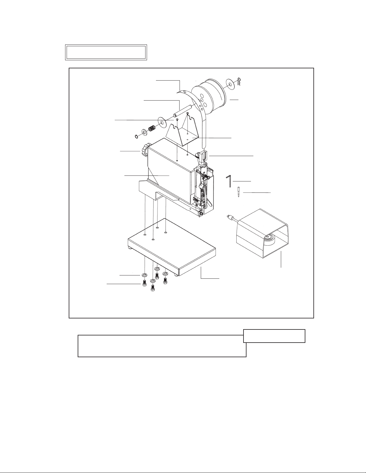
Wire straightness is important so that the stitches are loaded, driven and closed properly. Although
straightness is set at the factory, every roll of wire has varying degrees of twist which makes it
necessary for the user to properly straighten the wire prior to production. Easy steps for straightening
the wire are listed below.
MG10001A
9070 (2)
9067 (2)
2132BA
9043B
threading process. With the Swivel still removed, power the MiniStitcher on and switch the Trip
Mode Switch (PG10232), found on the back of the Machine, to single mode stitching. Replace the
Head Guard and trip the Foot switch to allow the wire to automatically thread between the Grip and
the Grip Holder. This will also cut off any excess wire below the Cutters.
9163
9046A
!

9
straight up and down, adjust the Wire Straightener Nut (9067) so that the Wire Straightener Pointer
(9070) turns counter-clockwise. Remember, the MiniStitcher works optimally if the Wire curves
slightly to the right. Allow enough Wire to be fed through the Head so that an accurate assessment
can be made. After an adjustment is made it takes approximately four to six stitches to take effect.
If the Wire is feeding too far to the right, adjust the Wire Straightener Nut so that the Wire Straightener
Pointer turns clockwise.
Front-to-Back Adjustment
Look at the Wire feeding through the Head from the side and make sure that it is straight
front-to-back. The Wire Straightener Eccentric (9067) on the Wire Guide Spring Bracket
(MG10001A) adjusts the curve if it is not straight. Setting the Wire Straightener Pointer (9070) at a
position comparable to 7:00 on the face of a clock is a good place to start. If the Wire is feeding too
far to the front, adjust the Wire Straightener Eccentric so that the Wire Straightener Pointer turns
clockwise. Allow enough wire to be fed through the Head, about four to six stitches, to make an
accurate assessment. If the wire is feeding too far to the back, adjust the Wire Straightener Eccentric
so that the Wire Straightener Pointer turns counter-clockwise.
Once the MiniStitcher has been threaded and the wire straightness has been obtained, it is time to
begin stitching. Replace the Swivel Assembly (9038M or 9038A), the Swivel Operating Hub (9163)
and the Swivel Operating Spring (9046A). Set the Trip Mode Switch (PG10232), found on the back
of the Machine, to single stitching.
NOTE: The continuous Trip Mode is used primarily for oiling
and wire straightness adjustment.
Activate the Foot Switch (PG10230) once to load a piece of wire into the Swivel. Even though the
MiniStitcher has been tested at the factory, the wire draw adjusted and the legs equalized, the
following are directions to make these adjustments if necessary. One control, the Face Plate
AdjustmentKnob(MG10013),controlsboththelengthoftheleftlegandwiredraw.
The overall length of the stitch is controlled by the amount of wire that is drawn from the spool after
each stroke of the MiniStitcher. To change the overall length of the stitch, loosen the Face Plate
Adjusting Lock Screw (9799) on the front of the Head.
Adjusting the Wire Draw (Figure 5)
Always disconnect the power cord before
making any adjustments or servicing the MiniStitcher
WARNING
!

Adjusting the Length of the Left Leg (Figure 5)
10
TurntheFacePlateAdjustmentKnobclockwisetoraisetheFacePlatewhichdrawsmorewire-
making the overall length of the stitch longer. If the overall length is too long, turn the Face Plate
AdjustmentKnobcounter-clockwisetolowertheFacePlateanddecreasethedrawofwirepulled
from the Wire Spool. Once the correct length of wire has been achieved, tighten the Face Plate
AdjustingLockScrew.Asaroughgauge,thedistancetheFacePlateisabovetheBonnet(2601R)
should be equal to the work thickness.
NOTE: If the Face Plate is adjusted too high (turning the Face Plate
Adjustment Knob too far clockwise) the Grip (9015) will lock in an open position
and draw no more wire. The MiniStitcher has a capacity of 1/4” and will allow no
more than that amount of wire to be drawn from the spool.
Adjusting the Stitch’s Left Leg
If after a few stitches, the length of
the stitch’s left leg is too short compared to
that of the right, you will need to adjust the
Wire Guide Spring Bracket (MG10001A).
LoosentheWireGuideSpringBracketScrew
(9075) found on the side of the Head. Turn the
Face Plate Adjustment Knob clockwise and
tighten the screw. If the length of the left leg
is too long, loosen the Wire Guide Spring
Bracket Screw and turn the Face Plate
Adjustment Knob counter-clockwise. After
the length of the stitch’s left leg is satisfactory,
make sure to tighten the screw again.
Figure 5 - Adjusting the Left Leg and Wire Draw
!
Do not operate the MiniStitcher Stitcher
until all guards are in place
CAUTION
!
9075
MG10013
9799
9046A
MG10001A
2601R
9015
9038M or
9038A

11
Stitching Process
The MiniStitcher has been specifically designed to use a solid Clincher Plate. For this reason,
adjustable work tables and table trips have not been installed on the MiniStitcher. Following is a brief
explanation of options available for the machine.
The Solid Clincher (MG10178) is attached to the Platform Weldment (MG10170A) on every
MiniStitcher.BecausetheClincherismountedtoastationaryClincherArm,thelegsofeachstitch
are bent when the wire is pushed through the stock and hits the Clincher as opposed to the Clincher
Points on moveable Clincher Plates coming up to meet the wire. Having fewer moving parts
supporting this process results in a more solid brace for the stitches as they are driven into the stock,
a more sustained capacity and fewer wear parts to replace.
Minor adjustments can be made to the Solid Clincher if necessary. Loosen the Screw (UA4808.3)
retaining the Solid Clincher on the Clincher Arm to adjust the Clincher side to side.
TheBackStop(MG10176)attachestotheClincherArmwithaThumbScrew(P2731)andisused
to consistently locate the depth of the stitch.
Solid Clinching (Figure 6)
Figure 6 - Solid Clinching
MG10170A
UA2804.6 (2)
MG10076
MG10178 UA4808.3
P2731

The Stitch Mode Switch (PG10232) is found on the back of the MiniStitcher. (The switch on the
left, looking from the rear of the machine.) There are two stitching modes: single or continuous.
Single stitching is used for production. In the single trip mode only one stitch will be released at a
time, no matter how long the trip switch is activated. With the continuous stitch mode, the machine
will continue to deliver stitches as long as the Foot Switch is activated. The continuous stitch mode
is used only for lubricating, testing and trouble-shooting.
Stitch Mode
The Trip Mode Switch (PG10232) is also found on the back of the MiniStitcher. (The switch on the
right, looking from the rear of the machine.) Either the foot trip or the table trip mode can be
selected even though the standard MiniStitcher comes complete with only a Foot Switch (PG10230).
TheContactTrip(MG10164)canbepurchasedseparatelyintheIMSK2KitandusestheTripMode
Switch toggled in the table trip mode.
BesurethattheFootSwitch(PG10230)ispluggedintotherearoftheMiniStitcherandtheTrip
Mode Switch is toggled for this mode before work is begun. The Foot Switch will not activate the
MiniStitcher if the Trip Mode Switch is toggled in the table trip mode.
Trip Mode
12

Trouble Shooting (Figure 7)
Following is a brief list of problems and solutions which covers the most common situations
encountered when stitching with the MiniStitcher. Most problems with stitches are due to incorrect
adjustments on the machine or to the normal wear of parts.
problem:ThemachinedoesnotcyclebuttheMainPowerSwitch(PG1022B)ison.
solution:Make sure the Power Cord (P2581 or PG10410) is properly plugged into a live
receptacle.ChecktoseeiftheCircuitBreaker(PG10234orPG10406)hasbeentripped.Ifso,push
it to reset. If it still does not cycle, make sure the Foot Switch (PG10230) is plugged in and the
correct Trip Switch position is selected. The Head Guard (PG10003) must be in place to fully depress
the safety interlock, otherwise the MiniStitcher will not function.
NOTE: If the Head Guard moves enough to lose contact with the Safety Switch (PG10229)
the Head Guard must be rotated upward to clear the Safety Switch and re-closed.
problem:The wire is being cut but dropped before it can be formed.
solution:Make sure that the wire is feeding straight, or slightly to the right, from the Wire Spool
through the Wire Straightener Eccentric (9067) and the Wire Straightener Nut (9067). Allow enough
wire to feed through the head and trip the MiniStitcher. If the problem continues, check to see if there
is enough tension in the Swivel Operating Spring (9046A). The Swivel has to get close enough to the
wireintheBenderBar(9013BA-25or9013BA-21x25)toengageit.ChecktheLatch(9014)andthe
Driver (9009-25 or 9009-21x25) for wear.
problem:There is inconsistent wire draw (indicated by varying lengths in the staple legs).
solution:Check to see if the Grip (9015) is worn and needs to be reversed or replaced, or if the
Grip Spring (9019) is stretched out. If an inconsistent amount of wire is being drawn from the Spool,
the legs of the staples will vary. Wire draw could also be restricted by the Tension Pawl (9098) or the
Tension Pawl Spring (9134) being too tight or too loose causing the wire to back up into the head. If
wire is not being easily fed between the Tension Pawl and the Wire Straightener Roll (9103) on the
Face Plate, consistent wire draw is adversely affected.
problem:More than one piece of wire is loading into the Swivel (9083M or 9083A).
solution:TheBenderBarFrictionPlug(9112B)maybewornaswellastheBenderBarFriction
Spring(9113B).IftheBenderBar(9013BA-25or9013BA-21x25)doesnotretractenoughtoallow
the Swivel Assembly (9038M or 9038A) to return to its normal position, the head will not drive the
wire into the stock and it will remain in the Swivel.
problem:Thewireisbeingbent,notcutorisjammingalongtheFacePlate(2132BA).
solution:First check to see that the Cutters (9048) do not have to be reversed or replaced. If their
surfaces are not dull check to see if the Wire Cutter Operating Slide (9049) is worn or if the Cutter
Holder in the Face Plate is worn.
13

14
Figure 7 - Troubleshooting
problem:Right Leg Short
solution:Shorten the left leg and then lengthen both of the stitch’s legs.
(See pages 10 - 11)
problem:Left Leg Short
solution:Lengthen the left leg. Check the Grip for wear and rotate or
replace it if needed. (See page 11)
problem:CornerBuckled
solution:Check the Driver for a chipped corner and rotate or replace it
if needed. (See page 21)
problem:Leg(s)Buckled
solution:Check the Wire Cutters for wear and rotate or replace if needed.
(See page 19)
problem:CrownBuckled
solution:Check Supporter Spring (9032) tension. If it is too loose
adjust it.
problem:Stitch in Pieces
solution:Clean and lubricate the Swivel. (See page 17)
problem:Corners of the Crown are Rounded
solution:Replace the worn Swivel.
problem:Legs are Spread or Contracted
solution:Readjust the Wire Straightener Eccentrics. (See pages 9 and 10)
Check the Wire Cutters for wear and rotate or replace if needed.
(Seepage19)ChecktheBenderBarforwearinthegroovesand
replace if needed.
!
Do not operate the MiniStitcher Stitcher
until all guards are in place
CAUTION
!

15
Maintenance
Lubrication (Figure 8)
Your MiniStitcher has been fully lubricated at the factory, but regular preventative maintenance will
result in superior performance and longer life of the machine. A good rule of thumb is to oil the
MiniStitcher’s critical points every five pound wire spool change or every month, whichever comes
first. Use one drop of any standard S.A.E #10 oil in the following lubrication points:
•atthetopoftheBonnet(2601R)on
either side of the Wire Guide Spring
Bracket(MG10001A)
•theoilholeintheSwivelOperating
Lever (9163) in the Hub
•theoilholesintheFacePlate(2132BA)
•ontheBenderBarLatch(9014)andon
the Grip (9015)
•theoilholeintheDrivingShaft
Connection Link (2215)
•theopeningintheSwivelHolder
(9043B)
•theWireCutterOperatingSlideslot
(9049)
•ontheWireStraightenerRolls(9065)
and Tension Pawl (9098)
Figure 8 - Lubrication and Cleaning
9043B
9038M or
9038A
9046A
2132BA
9049
2215
9014
9015
MG10001A
9163
9098 9065 (3)
9129B

In time, you will need to replace some parts in your MiniStitcher. When this happens, first locate
the needed part in one of the following diagrams. Then locate the DeLuxe Stitcher part number and
contact your Graphic Arts Representative to order the part by the part number, description and
quantity. Also, be sure to provide the wire size being used in your MiniStitcher.
Ordering Spare Parts
In addition to proper lubrication, routine cleaning is important for the maintenance of your
MiniStitcher. The following areas should be cleaned every three months:
•Swivel Assembly (9038M or 9038A): remove and wash in an oil-dissolving solvent, dry
and relubricate.
•Swivel Holder (9043B): clean inside the Swivel hole with an oil-dissolving solvent.
•Swivel Operation Lever and Stud: remove the Swivel Operating Spring (9046A) and
Hub(9163).CleantheSwivelOperatingSpringStud(9129B)andtheholesoftheHub,
relubricate and replace.
Note: Use care when replacing the Swivel Operating Hub (9163) as direction is critical and
the Swivel Operating Lever to avoid seriously damaging the head.
•Anywhere that dust, oil or pieces of wire and paper have built up - for example: the Grip,
Clincher Points and around the Wire Straightener Rollers.
Cleaning (Figure 8)
16
!
Always disconnect the power cord
before any maintenance or adjustments are
made to the MiniStitcher
CAUTION
!

17
Replacing Spare Parts
Following are some of the
more common wear parts
which will need to be
removed and replaced in
your MiniStitcher. Most
replacements require the
Stitcher Head to be removed
from the MiniStitcher. The
instructions on how to
remove the head will be
given first, then a more
specific description for
each common wear part
will follow.
General Maintenance
and Repair (Figure 9)
While some adjustments
can be made to the
MiniStitcher with the
stitcher head in place, most
maintenance and general
repairs have to be made
with the stitcher head
removed from the machine.
Cut the wire from the wire
spool just below the Wire
Guide Spring Bracket
(MG10001A).
Pull the remaining wire
out from the bottom of the
Figure 9 - Removing & Disassembling the Stitcher Head
!
Always disconnect the power cord
before any maintenance or adjustments are
made to the MiniStitcher
CAUTION
!
MG10001A
MG10011A
9112
2137A
9012A
9075
9014
2132BA
9003A
9050B
9026A 9022
9017
9113
9115
9038A
9038M
MG10026
9050B
2215
MG10009A
9163
9129B

18
Removing and Replacing the Wire Cutters (Figure 10)
The Wire Cutters (9048) have
two cutting surfaces, each of which
may be used by reversing the ends
and positioning in the Face Plate
(2132BA). To change or reverse
the Wire Cutters, they must be
removed from the Face Plate.
Loosen the Screws (UA2305.2) in
the Face Plate Clips (9056) and the
Screw (0084) in the Solid Face
Plate Clip (9171). Once the clips
are
loosened, the Face Plate can be
tilted away from the Bonnet
(2601R) to remove the Wire
Cutters. Slide the existing or new
Wire Cutters into the cutter holder
in the Face Plate - with the tongue
of the upper cutter facing the front and the tongue of the lower cutter facing the back and into the
WireCutterOperatingSlidegroove.BeforetighteningtheFacePlateClipScrews(UA2305.2)and
the Solid FacePlate Clip Screw (0084), make sure that each Cutter has slipped into position in the
Face Plate and in the Wire Cutter Operating Slide. (9049) Press the Face Plate under the Face Plate
Clips and tighten the Face Plate Clip Screws. Always rotate the MiniStitcher manually before
switching the power on to ensure free mechanical movement. This will prevent serious damage to
the Head.
Figure 10 - Removing the Wire Cutters
!
Always disconnect the power supply before
assembling the MiniStitcher or making any adjustments.
CAUTION
!
9049
2132BA
9048 (2)
9056
UA2305.2
9171
stitcher head. Remove the Wire Guide Spring (MG10009A) from the Wire Guide Spring Bracket
(MG10001A).
Loosen the Bonnet Clamp Eccentric Handle (9003A) and remove the Stitcher Head from the
MiniStitcher.PlacetheHeadonacleanworkarea.BeawarethattheDrivingShaftConnectionLink
(2215) is removed from either the Driving Slide Assembly (2137A) or the Crank (MG10031A).
This manual suits for next models
2
Table of contents
Other DeLuxe Stitcher Sewing Machine manuals

DeLuxe Stitcher
DeLuxe Stitcher M19 Series User manual

DeLuxe Stitcher
DeLuxe Stitcher G5 User manual

DeLuxe Stitcher
DeLuxe Stitcher 18AW User manual

DeLuxe Stitcher
DeLuxe Stitcher 19-aw User manual

DeLuxe Stitcher
DeLuxe Stitcher StitchMaster SM-A25 Installation guide

DeLuxe Stitcher
DeLuxe Stitcher G5 User manual

DeLuxe Stitcher
DeLuxe Stitcher M7 Series User manual

DeLuxe Stitcher
DeLuxe Stitcher M30 Series User manual

DeLuxe Stitcher
DeLuxe Stitcher M2 Series User manual

DeLuxe Stitcher
DeLuxe Stitcher G8 User manual