DEMA MixRite TF-25 User manual

MixRite TF-25
2
MixRite TF 25 Proportional Dosing Injectors
We congratulate you on your purchase of one of MixRite's excellent products.
It is important to devote a few minutes to carefully reading the explanations and recommendations
in this user's manual in order to get the most from the proportioning dosing injector.
Operation of the injector
The proportioning dosing injector is fitted on the water line. The flow of water passing through the
injector activates it and causes the pumping of liquid additive and inserts it in a relative quantity
into the water line.
The MixRite TF 25 proportioning dosing injector will operate in the following
conditions:
The flow rate of the water passing through the MixRite TF 25 is between 2 and 25 m3/hour (530-
6600 gal/hour).
The water pressure is between 1 and 8 bar (14-120 PSI).
Head loss for MixRite TF 25: Minimum flow 0.1 Bar – Maximum flow 1.5 Bar
The water & air temperature are not less than 4ºC (40ºF) and not more than 40ºC (104ºF)
The flow rate of the additive can be adjusted relative to the flow rate of the water in the range of
0.1% to 1% for Model 001 and of 0.3% to 2.5% for Model 002 and in the range of 1% to 5.5% for
Model 005.
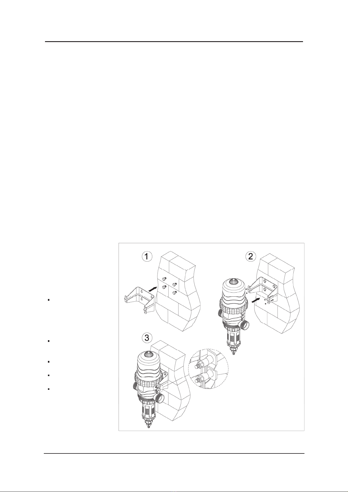
Installation of the
injector
Option A: Wall
mounting bracket
(Supplied as standard)
The package should
contain:
A proportioning dosing
injector to which are
attached two couplings
for a 63mm plastic pipe
Or two 2" threaded
couplings.
A flexible suction tube
to which is attached a
flat 1" seal and a filter.
A Bracket, 4 SS screws
M8*45, 4SS nuts M8.
Spanner for TF cover
nut.
User's manual
3
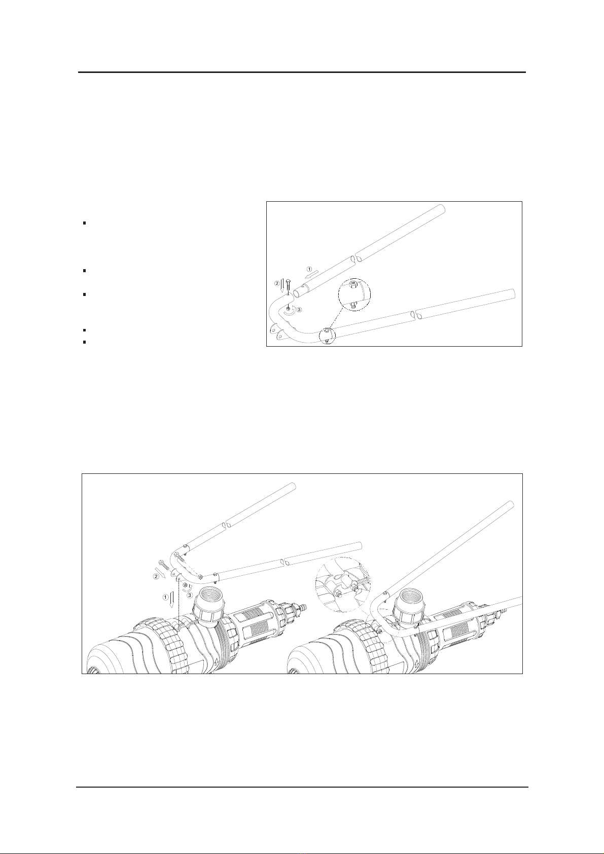
Option B: With stand
Installation of the injector (correct installation is with the stand supplied
By Tefen) – OPTIONAL
The package should contain:
A proportioning dosing injector to
which are attached two couplings
for a 63mm plastic pipe
Or two 2" threaded couplings.
A flexible suction tube to which is
attached a flat 1" seal and a filter.
A stand comprising 4 legs, 2
arched braces, 4 bolts with 8 mm
nuts and 4 bolts with 6mm nuts.
Spanner for TF cover nut.
User's manual
To assemble the stand
Insert the narrow part of the leg into the opening in the tube in the arched brace. Make sure that
the holes in the leg are opposite the holes in the arched brace. Insert the 6mm bolt and tighten the
nut. Repeat with the other legs.
Attach the arched brace to the body of the injector (1) with the 8 mm bolt (2) and tighten the nut
(3). Repeat with the other arched brace.
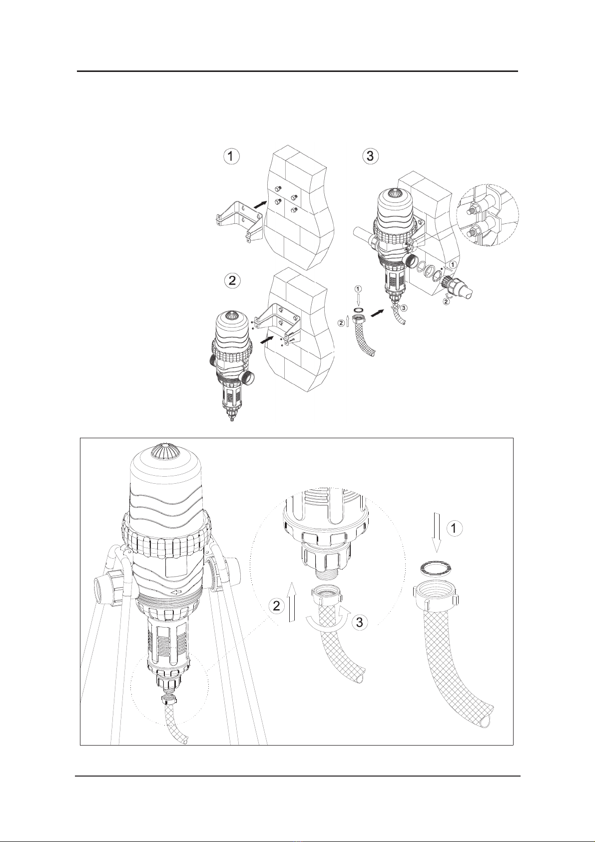
4
Connection of the
suction tube
Insert the flat seal into
the nut of the coupling
on the end of the tube
(1). Thread and tighten
the nut to the inlet
valve on the underside
of the injector. Make
sure that the nut is
threaded and
tightened properly
(2,3).
5
Connection of the injector to a 2" line
Note the direction of the water flow. Assemble the injector with the arrow stamped on the body of
the injector pointing in the direction of the water flow. Connect the injector using the plastic
couplings.
For a drinking water line all injectors must have a backflow prevention valve installed in front of the
injector on the main water line, in accordance with local regulations.
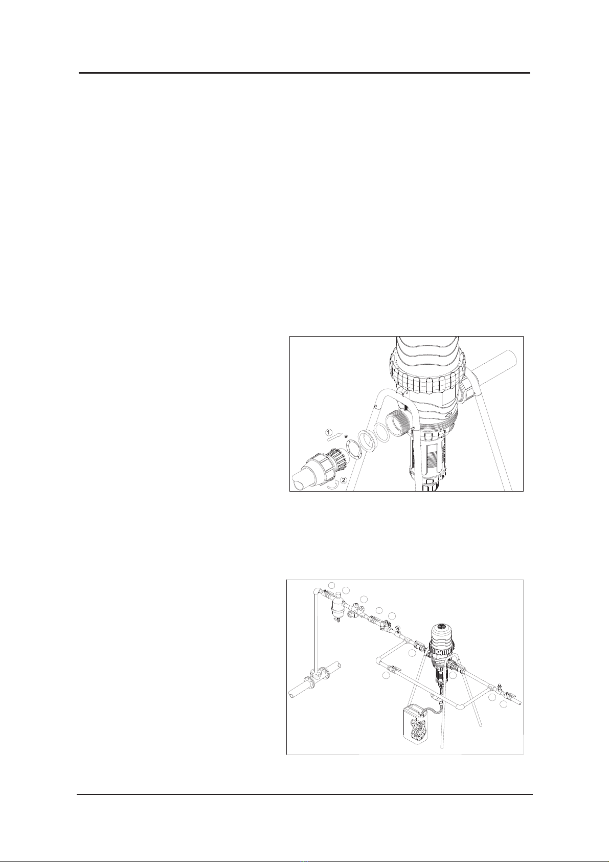
Connection of the injector to a 63mm plastic pipeline
Note the direction of the water flow. Assemble the injector with the arrow stamped on the body of
the injector pointing in the direction of the water flow.
Cut and round the edges of the inlet and outlet pipes. The distance between the end of the inlet
pipe and the end of the outlet pipe should be 22cm.
Remove the 63mm nut and the white ring from the injector, and fit them on to the pipe a short
distance from the end.
Check that inside the injector there is the
seal for 63mm accessories and that the
bushing for the 63mm seal closes it from
the outside.
Insert the pipe into the inlet and outlet
opening and push hard so that the pipe
penetrates, and passes the seal, and is
stopped at the end of the route. To ease
Insertion apply a little silicon grease to
the end of the pipe.
Push the white ring until it contacts the
threaded part, and tighten the nut.
Repeat the process in order to connect
the pump to the pipe on the other side.
* Optional Special grip ring for P.V.C pipes
Installation of the injector on a direct line
It is recommended to fit a main valve at the beginning of the line (1), and a water filter of 200
mesh (2). A backflow prevention valve (3) must be fitted to a drinking water line, in accordance
with local regulations, in order to prevent entry of chemicals into the drinking water. Then place
the following pressure reducer (4),
to protect the injector from excess
pressure; a valve before the inlet to the
injector (5); a valve after the outlet (6);
an anti vacuum valve (7) to prevent a
siphon effect when the injector is not
working; and operating valves (8) for the
branch lines.
It is advisable to add a bypass pipe (9)
that will permit diverting the water flow
through the bypass pipe if there is a need
for irrigation without any additives, or for
dismantling the injector.
2
1
3
4
5
6
8
7
9
1

6
Installation of the injector on a bypass line
It is necessary to fit the proportional dosing injector on a bypass line when irrigating with a flow
rate higher than 25 m3/hour. The bypass enables only part of the water flow to pass to the
Injector and activate it, while the rest passes through the main line. Using the choke valve on
the main line, the flow of water passing through the main line is regulated so that only
A proportion of the flow passes through the bypass and activates the injector. The metering must
be calculated in accordance with the flow rate passing through both lines.
It is necessary to fit a main valve at the beginning of the line (1), water filter of 200 mesh (2),
backflow prevention valve (3) must be fitted to a drinking water line, according to local
regulations, in order to prevent entry of chemicals to the drinking water. A pressure reducer (4),
a T connection for diversion from the main line to the bypass, a valve(5)on the bypass before the
inlet to the proportioning dosing injector, a valve (6) after the outlet from the injector on the
bypass, and a T connector for the return to the main line. On the main line between the bypass
junction and the return connection a choke valve should be fitted (7), preferably an angled valve,
to regulate the flow rates between the main line and the bypass.
After the return connection from the bypass there should be fitted anti vacuum valve (8) and
valves for the branch lines (9).
A- High pressure
B- Low pressure
12
3
4
5
6
8
9
7
A
B
7
Installation of two injectors in parallel
When the water flow rate in the irrigation line is higher than the maximum nominal flow rate of
the injectors, the water may be divided between two units. If the 2 injectors are used for
pumping the same type of additive the scales should be adjusted in an identical manner to the
same level of metering. Two different additives may be metered at different levels. The metering
in each unit must be calculated for each flow rate passing through the two injectors.
It is necessary to fit a main valve at
the beginning of the line (1), water
filter of 200 mesh (2), backflow
prevention valve (3) must be fitted to
a drinking water line, according to
local regulations, in order to prevent
entry of chemicals to the drinking
water. A pressure reducer (4), a T
junction from the main line into 2
lines (5). On each branch there
should be fitted a regulation valve
(6), the injector, a non-return valve
(7) after the outlet from the injector
and a return connection to the main
line (8) anti vacuum valve (9).
Both sides of the instillation must be
identical.
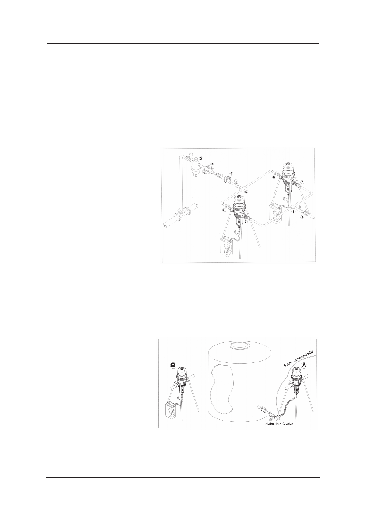
Connection to the additive tank
The suction tube should be connected to the additive tank (preferably about 5cm above the
bottom) – diagram A. The liquid additive must pass through a chemical resistant filter of 200
mesh, which must be cleanedregularly.
When making the connection to a large additive tank, use a chemical resistant valve and a
normally closed hydraulic valve to prevent a siphon effect.
The normally closed hydraulic valve should be connected to a hydraulic command tube.
If the additive is pumped from inside
an open tank (diagram B) a heavy
weight should be attached to the end
of the suction tube that will keep the
opening of the suction tube inside
the additive and prevent the tube
from floating and falling outsidethe
tank.
Make sure that the level of the
additive is always below the injector.
Otherwise uncontrolled flow of the
additive may occur.
8
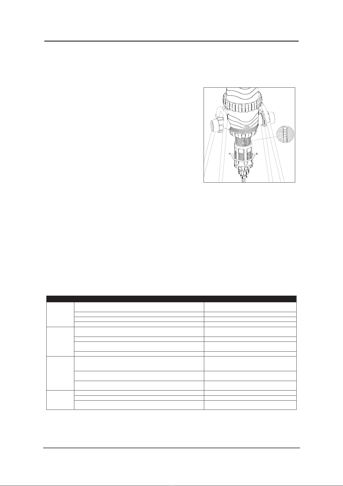
Adjustment of metering
On the metering cylinder there is a scale indicating the
percentage of additives. When the injector is not
operating and there is no pressure in the unit, turn the
adjustment sleeve clockwise to increase the amount of
additive or turn counterclockwise to decrease the amount
of additive. The actual rate should be checked. If
necessary, adjust by increasing or decreasing the
adjustment sleeve.
Servicing
The water filter at the inlet to the injector and the additive
inlet filter should be cleaned frequently.
* NOTE: If it is planned not to use the injector for a long time, it should be operated for a few
minutes with the suction tube inside a tank of clean water, in order to flush away traces of additive
from inside the injector and prevent them from adhering to it.
If there is a drop in temperature below 4°C (40°F) risk or a risk of freezing, the injector should be
drained. In order to drain the unit, close the inlet and outlet valves properly. Unscrew and
dismantle the 1" coupling nut that connects the suction tube, press on the non-return valve
(insert your finger or a small rod) in order to drain all the water trapped in the unit, while
pressing the air bleed valve at the top of the injector (with your other hand).
Suggested maintenance
Replace injection seals every 12 months:
Kit # 1- seals 0.1-1%(Catalog No. 35000000008)
Kit # 2-TF seals 0.2-2.5% (Catalog No. 35000000002)
Kit # 3-TF seals 1-5% (Catalog No. 35000000003)
Troubleshooting guide
Problem Check Solution
The injector is fitted with the arrows in the opposite direction to the
water flow direction.
Fit the injector with the arrows in the direction
of flow.
.sevlavehtnepO.desolcerasevlavteltuodnatelniehT
.retlifehtnaelC.dekcolbsiretliftelniehT
The injector
does not
work
.evlavniamehtnepO.erusserpetairporppaehttawolfretawonsierehT
Open the nut locking the motor cover, remove the motor cover, and
remove the mechanism. Check if the motor seals are defective. Replace the motor seals.
.sgnirpselggotehtecalpeR.nekorberasgnirpselggotehtfikcehC
Check if the seals above the valves are defective or have been
displaced. Replace the seals.
The injector
has stopped
working
Check if one of the parts of the mechanism is broken. Replace the broken part.
The leak is from the connection between the body and the cover.
Open and remove the motor cover, replace the
seal, fit the cover, and thoroughly tighten the
cover locking nut.
The leak is from the connection of the suction tube. Remove the suction tube, replace the defective
seal and reconnect.
There is a
leak from
the injector
The leak is from the non-return valve. Dismantle the non-return valve and replace the
defective seal.
.retlifehtnaelC.dekcolbsiretlifnoitcusehT
Dismantle the injector unit and check if the suction seal is defective. Replace the suction seal.
There is no
suction in
the additive
inlet .evlavnruter-nonehtecalpeR.evitcefedsievlavnruter-nonehT
For advice, technical support and purchase of spare parts, contact the authorized sales
representative in yourarea.
Table of contents
Other DEMA Water Pump manuals


Popular Water Pump manuals by other brands


 Series Service manual")
SHIMGE
SHIMGE SG(m) Series Service manual

Samoa
Samoa UP03B Series Parts and technical service guide

Pacific hydrostar
Pacific hydrostar 69297 Owner's manual & safety instructions

Acquaer
Acquaer CJE050-1 owner's manual

T.I.P.
T.I.P. FlatOne 6000 INOX Translation of original operating instructions

SPX
SPX L1600 instruction manual


