Demeq QH5-D User manual


P/N: QHD 501 –ENG –Rev 3 –2012

I
Chapter 1
First steps
1.1
Know the QH5
1
1.1.1
Front panel
2
1.1.2
Connectors
2
1.2
Install or replace batteries
3
1.3
Connecting the impact device
5
1.4
Using the impact device
6
1.4.1
Loading the impact body
6
1.4.2
Release and measure
6
1.5
The “Q” key
7
1.6
Display illumination and contrast
7
1.6.1
Display backlight illumination
7
1.6.2
Display contrast
8
1.7
Locking and unlocking the keypad
8
Chapter 2
Measuring with the QH5
2.1
Numerical measure screen (Normal)
10
2.1.1
Screen mode-1 (Datalogger)
10
2.1.2
Screen mode-2 (Material)
11
2.1.3
Screen mode-3 (Statistics)
11
2.2
Keys in numerical measure modes
12
2.3
Graphic measure screen (Histogram)
14
2.4
Keys in the graphic measure screen mode
15
2.5
Set impact device angle
16
2.6
Select material and hardness unit
17
Chapter 3
Menu system and editing
3.1
Instructions on using the menu system
19
3.1.1
Text editor
20
3.2
Main menu
22
3.2.1
Change hardness unit
22

II
3.2.2
Alarm settings
23
3.2.3
Set histogram range
24
3.2.4
Select language
24
3.2.5
Unit information
25
3.3
General configuration options
25
3.3.1
Set time and date
26
3.3.2
Set time and date format
26
3.3.3
Set keypad sensitivity
26
3.3.4
Set auto-off time
28
3.3.5
Adjust display contrast
28
3.3.6
Beep activation
29
3.3.7
Introduction screen
29
3.3.8
Owner information
29
3.3.9
Lock configuration options
31
3.3.10
Model upgrade licenses
32
3.3.11
Return to factory default settings
33
3.4
Measuring configuration options (Hardness)
34
3.4.1
Set impact device angle
34
3.4.2
Select material
35
3.4.3
The “Plus” key
35
3.4.4
Set group (N) number
36
3.4.5
Select measure mode
37
3.4.6
Create custom or user units
37
3.4.7
Select impact device type
41
3.4.8
Set alarm for impact device tip
42
3.4.9
Return to factory default settings
42
III
Chapter 4
Using the Datalogger
4.1
How data is organized
43
4.2
Memory menu
44
4.3
Creating a file
44
4.4
Actions over single files
45
4.4.1
View data in a single file
46
4.4.2
The “Q”key in a grid
47
4.4.3
The “Q”key in a histogram
48
4.4.2
Send data from a single file
48
4.4.3
Rename a file
49
4.4.4
View file size
49
4.5
Actions over all files
49
4.5.1
Send all files
49
4.5.2
Erase all files
49
4.6
Quick memory menu (Mem key)
50
4.7
Connecting to PC with DataCenter
51
4.8
Datalogger configuration
52
4.8.1
Configure communications
52
4.8.2
Capture modes
54
4.8.3
Advanced configuration
54
Tips on how to measure correctly
Technical specifications
Additional information
Unit maintenance
QH5 accessories
Error messages
Our website: www.demeq.com
Technical Support

IV
And thank you for purchasing a QH5 rebound hardness tester.
At dmq we develop, manufacture and distribute software and quality
control instruments offering innovation and solutions that come as a
direct result of listening to your needs as a user. We apply some of the
latest technology available in the industry to build instruments that are
robust, precise, and easy to operate.
We are convinced that our products would not be complete without
permanent technical and after sales support. So in addition to a great
product we offer:
Quick answers to your inquiries.
Unlimited access to technical information as well as
application notes.
Special offers for registered customers.
Firmware and software upgrades at no charge.
Attention to your inquiries and suggestions.
We hope that the QH5 will meet and exceed your application needs.

V
The information included in this manual applies to all QH5 series
portable hardness testers including models D, G and M.
dmq is a registered trademark of demeq S.R.L and its affiliate
companies.
The information contained in this manual is intended to educate users
on the operation of the QH5 impact hardness testers. Failure to read
and understand this manual can lead to measurement errors. Decisions
based on measurements and or results that are erroneous can lead to
property damage, personal injury or even death. Demeq S.R.L assumes
no responsibility as a result of the improper use of our instruments.
ASTM A956
Correct use of an impact hardness tester requires that you take all of
the following into consideration:
Select the instrument as well as the impact device that is best
suited for your application.
Know the specific requirements for the test you will be
conducting.
Make sure that the person operating the unit has been
trained on its use.

VI
This manual provides all of the information needed to configure and
operate the QH5 hardness tester. However there are additional factors
that can affect tests done with this instrument. Specific information on
those factors is outside the scope of this manual. When in doubt you
should always seek expert advice or refer to specific textbooks on
portable hardness testing. Additional information can also be found on
the internet and through local government agencies as well as in
technical institutes.
All QH5 units operate on the Leeb impact rebound method where the
ratio between the impact and rebound velocities of the impact body
that is released on the test piece, are measured to establish a Leeb
hardness value. The step by step process is represented in figure 1 as
follows: 1, the impact body is released and travels inside the impact
device; 2, the impact body tip hits the test piece; 3, the impact
produces a rebound.
Figure 1: Representation of the Leeb rebound method
VII
The measured Leeb value (HL) represents a direct hardness value that is
converted to other hardness units such as Brinell, Vickers, Rockwell and
Shore. Both the HL value and another selected hardness unit are
displayed on the unit screen simultaneously.
There are a number of available impact devices and each one of them
is different and ideal for specific applications. In this section general
information, measuring ranges and recommended applications are
briefly explained for each impact device type.
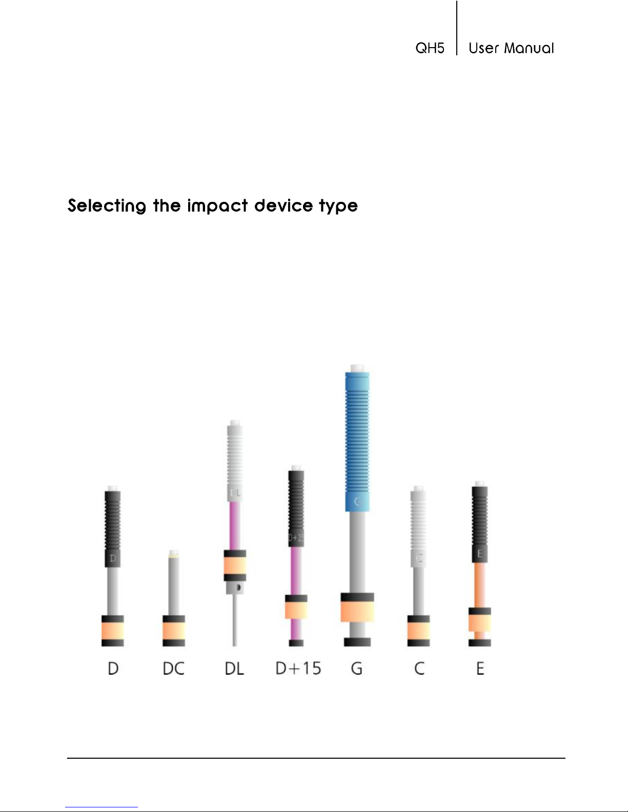
In figure 2 a representation of the physical aspect of each one of the
impact device types available for the QH5 is shown.
Figure 2: Representation of Impact device types for QH5 units

VIII
Impact device type D
This is the standard device in impact hardness testing because it
measures in all of the units and materials covered with the QH5. The
type D impact device covers the widest range of applications.
Impact device type DC
This device type, just like impact device type D, can also measure in all
units and materials but features a much shorter body (50mm) making
ideal for measurements in hard to reach places that cannot be
accessed with a type D device. Unlike impact device D that is spring
loaded, device DC is loaded manually
Impact device type DL
The long and thin tip on impact device type DL allows access to very
narrow areas that cannot be measured with any other impact device.
This device measures steel only.
Impact device type G
This impact device type includes a large hardness tip that is 5mm in
diameter and it also releases the highest impact energy at 90 N*mm
allowing its use over rough surfaces such as those in founded and
forged pieces and in grey cast iron.
Impact device type C
On device type C the impact tip produces the less amount of energy
when compared to other device types (up to 25% less than device type
D) therefore becoming the best choice for measuring treated surfaces
on steel parts and for measuring smaller pieces. The lower release
energy level produces the smaller test piece indentation. This device
measures steel only.

IX
Impact device type E
Impact device E uses a synthetic diamond tip (all other impact device
types use tungsten carbide tips). The diamond tip allows it to measure
harder test pieces such as those made out of template steel. This device
type measures steel only and extends the Vickers range to 1211HV
(device type D measures up to 940HV).
The table below shows detailed technical information on each impact
device type.
Parameter (Unit)
Impact device type
D/DC
D+15
DL
C
G
E
General characteristics
Length (mm)
147/86
162
202
141
254
155
Diameter (mm)
20
20
20
20
20
20
Weight (g)
75/50
80
100
75
250
80
Max Hardness (HV)
940
940
950
1000
650
1200
Impact device tip
Diameter (mm)
3
3
2.78
3
5
3
Hardness (HV)
1600
5000
Material
Tungsten carbide
Diamond

X
Impact body
Energy (N*mm)
11
11
11
3
90
11
Mass (g)
5.5
7.8
7.3
3
20
5.5
Surface test piece requirements
Rugosity ISO
N7
N7
N7
N5
N9
N7
Rugos. RT (µm)
10
10
10
2.5
30
10
Rugos. RA (µm)
2
2
2
0.4
7
2
Minimum test piece weight (Kg)
Stand alone
5
5
5
1.5
15
5
With solid support
2
2
2
0.5
5
2
Coupled with
paste
0.1
0.1
0.1
0.02
0.5
0.1
Minimum test piece thickness (mm)
Coupled
3
3
3
1
10
3
Surface thickness
0.8
0.8
0.8
0.2
—
0.8
Test piece impact indentation
On parts up to 300HV
Diameter (mm)
0.54
0.38
1.03
0.54
Depth (µm)
24
12
53
24
On parts up to 600HV
Diameter (mm)
0.45
0.32
0.90
0.45
Depth (µm)
17
8
41
17
On parts up to 900HV
Diameter (mm)
0.35
0.30
—
0.35
Depth (µm)
10
7
—
10

XI
This section provides an overview of basic impact device components.
Figure 3: Impact device components
Figure 3 is a representation of the most important parts that make up
an impact device and the procedure used to remove the impact device
tip. Over time and depending on the number of measurements that
you make, the impact tip located on the impact device body must be
replaced. In order to do this turn the support ring clockwise (see figure
3-1) until the ring is released and the impact body falls off (figure 3-2).
Make sure you catch the impact body or that you work over a soft
surface where the impact body can fall on without being damaged.
Remove and replace the impact tip making sure everything is perfectly
clean and repeat this procedure to re-assemble the impact device.

XII
All QH5 series portable hardness testers are for industrial use only and
cannot be used in medical applications. The QH5 operates on two AA
size batteries. We strongly recommend that you use only top brand
name alkaline batteries.
Disposal of your QH5 and its components must be done in compliance
with all applicable regulations.
Because of its complexity level, software is never really completely error
free. For this reason in software controlled instruments always make
sure that the operations required for your application are in correct
working order.
Demeq S.R.L provides a limited warranty for a period of 2 (two) years
on electronic units and for 6 (six) months on transducers from the date
of purchase and may be extended for up to 5 years.
Every instrument undergoes thorough testing during manufacturing as
well as before shipping. In the event warranty service where to become
necessary, demeq S.R.L and or your local distributor or representative
will make a reasonable effort to replace your defective unit with
another new or used unit, while your instrument undergoes warranty
repair.

Chapter 1 1
Figure 1.1: Front of the unit
1. Graphic LCD display with LED backlight illumination
2. Move Left key / View partial statistics (Stat)
3. Move Up key / Manually store a value (Store)
4. Move Right key / Switch to graphical measure mode screen
(Graph)
5. Menu key / Enter and exit measure screen / Exit and return to
menus (Home)
2 Chapter 1
6. Move Down key / Quick access to memory menu screen
options (Mem)
7. Change backlight illumination key (On, Off, Auto)
8. Enter key / Edit values on the measure screen (Edit)
9. The key: Power On and Shutdown (touch and hold for 2
seconds) / Make quick and short touches to activate special
features
10. The key: Direct measure screen access from any menu
screens / User selectable functions
11. Horizontal scrolling center point (lock and unlock keypad on
measure screen)
12. Vertical scrolling center point (adjust LCD contrast)
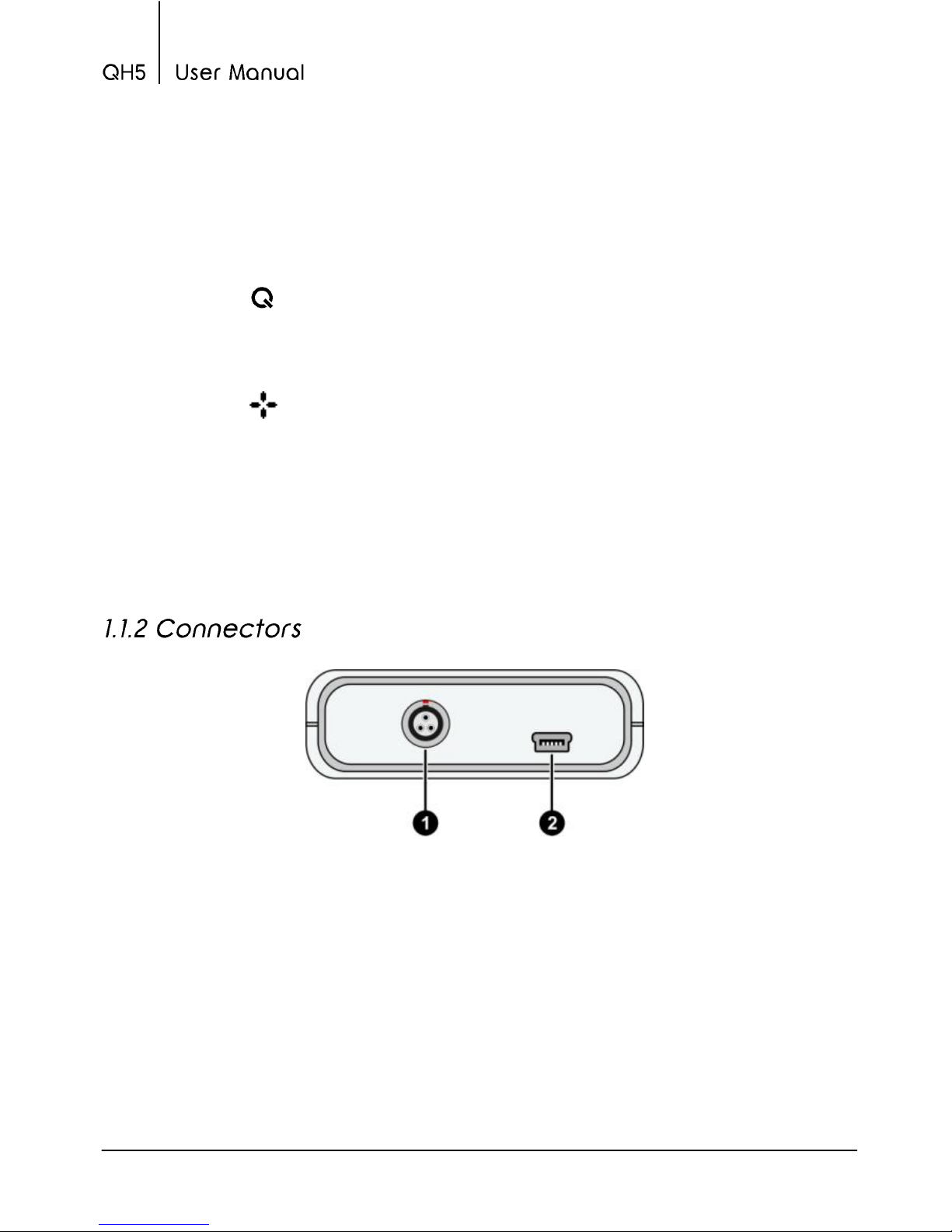
Figure 1.2: Unit connectors
1. Impact device connector type Lemo 0B
2. USB mini connector to connect to PC using a USB cable
Chapter 1 3
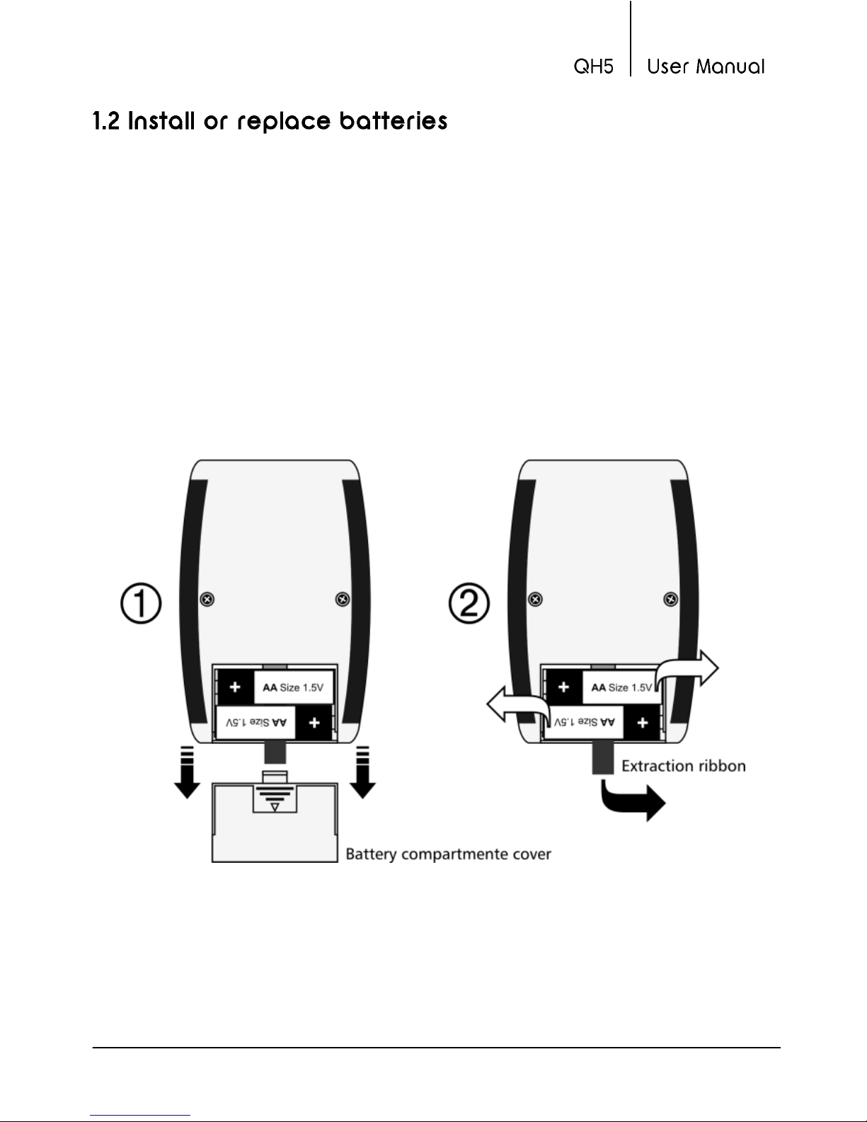
The QH5 is powered by 2 (two) AA batteries that are placed in the
battery compartment located in the back of the unit. To gain access to
the battery compartment slide the cover as shown in figure 1.3-1 and
gently push the extraction ribbon upward and slightly towards the
right to release the batteries (figure 1.3-2).
When you install new batteries, first insert the positive end of each
battery so that it coincides with the positive pole inside the battery
compartment as you see in figure 1.4-1.
Always leave the extraction ribbon underneath the batteries.
Figure 1.3: Removing batteries

4 Chapter 1
Figure 1.4: Replace / Insert batteries
Notes
Always use new alkaline top brand batteries for
extended battery life.
Do not mix new and old batteries. Always replace both
batteries.
Rechargeable batteries type NiMH can be used but will
result in less time of continuous operation.

Chapter 1 5
Important
Do not remove batteries while the unit is powered as
this may affect the Datalogger (See Appendix:
“Additional information, Error Messages”)
The QH5 uses a type Lemo 0B 3-pin connector located on top of the
unit. All dmq impact devices are provided with Cal-Tag technology
allowing you to easily switch or replace impact devices with no need to
calibrate the unit. Universal non-brand impact devices can also be used
as long as they have the same connector, but dmq does not guarantee
their performance.
To connect the impact device simply
align the red dot on the male
connector with the red dot on the
female connector located on the unit
and press gently until connected (see
figure 1.5)
To release the impact device hold the
knurled section on the male connector
and gently pull out.
Never remove the connector using the
cable.
Figure 1.5: Connecting the impact device
6 Chapter 1
The procedure explained herein is applicable to all impact device types
except for impact device type DC as it does not use a spring loading
mechanism.
Place the impact device over the surface you want to measure and load
by gently pushing the moving body of the impact device in the same
direction as the test piece surface. Keep pushing the moving body until
you reach the bottom limit and then bring the moving body back to its
initial position.
The impact device is now loaded and ready to be used.
Once the impact device has been loaded use one hand to firmly hold
the bottom of the impact device (the part that touches the surface you
want to measure) against the surface and use your other hand to press
the release button located on top of the impact device.
After pressing the button, the impact tip will hit the test piece surface
and a hardness value will immediately be displayed.
Repeat this same procedure for each measurement.
Important
The Leeb method for hardness testing has requirements
and limitations that must be considered in order to
obtain reliable and accurate measurements (See
Appendix: “Tips on how to measure correctly”)
This manual suits for next models
2
Table of contents
Popular Test Equipment manuals by other brands

Bms Bulut Makina
Bms Bulut Makina DIGIROCK-RB Operational manual

Elenco Electronics
Elenco Electronics RS-500 instruction manual

PCE Health and Fitness
PCE Health and Fitness PCE-RT 2300 user manual

Hantek
Hantek DSO-3004 USB Series user manual

Fluke
Fluke 975 AirMeter Application note

BEAMEX
BEAMEX MC5-IS user guide


