manuals.online logo
Brands
  1. Home
  2. •
  3. Brands
  4. •
  5. Megger
  6. •
  7. Test Equipment
  8. •
  9. Megger TTR 550503 User manual

Megger TTR 550503 User manual

Other Megger Test Equipment manuals

Megger MEG10-01 User manual

Megger

Megger MEG10-01 User manual

Megger SPG 40 User manual

Megger

Megger SPG 40 User manual

Megger BT 500-IS-1 User manual

Megger

Megger BT 500-IS-1 User manual

Megger S1-552/2 User manual

Megger

Megger S1-552/2 User manual

Megger PAT4DV/3 User manual

Megger

Megger PAT4DV/3 User manual

Megger BM5200 User manual

Megger

Megger BM5200 User manual

Megger MPRT 8415 User manual

Megger

Megger MPRT 8415 User manual

Megger MIT221 User manual

Megger

Megger MIT221 User manual

Megger BM121 User manual

Megger

Megger BM121 User manual

Megger MIT400/2 Series User manual

Megger

Megger MIT400/2 Series User manual

Megger BALTO Modular User manual

Megger

Megger BALTO Modular User manual

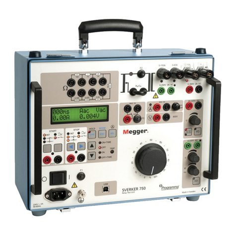
Megger SVERKER 750 User manual

Megger

Megger SVERKER 750 User manual

Megger PAT150-DE User manual

Megger

Megger PAT150-DE User manual

Megger Vidar User manual

Megger

Megger Vidar User manual

Megger MET1000 User manual

Megger

Megger MET1000 User manual

Megger BITE 2 User manual

Megger

Megger BITE 2 User manual

Megger LT310 User manual

Megger

Megger LT310 User manual

Megger OTS60SX/2 User manual

Megger

Megger OTS60SX/2 User manual

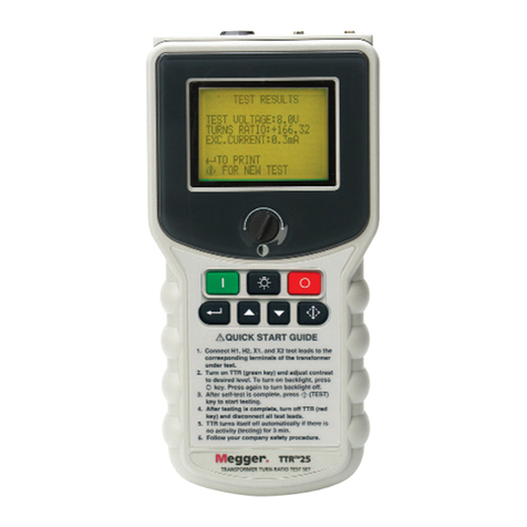
Megger TTR25 User manual

Megger

Megger TTR25 User manual

Megger DET2/3 User manual

Megger

Megger DET2/3 User manual

Megger BMM500 Series User manual

Megger

Megger BMM500 Series User manual

Megger TTR320 Series User manual

Megger

Megger TTR320 Series User manual

Megger MIT400 Series User manual

Megger

Megger MIT400 Series User manual

Megger MFT-X1 User manual

Megger

Megger MFT-X1 User manual

Popular Test Equipment manuals by other brands

Ambit P.F. Series instruction manual

Ambit

Ambit P.F. Series instruction manual

RJG Lynx Sensor Tester operating instructions

RJG

RJG Lynx Sensor Tester operating instructions

Mark-10 TT02 Series user guide

Mark-10

Mark-10 TT02 Series user guide

Martel 3001 Operator's manual

Martel

Martel 3001 Operator's manual

ElproSys DiagProg4 instruction manual

ElproSys

ElproSys DiagProg4 instruction manual

Redtech TRAILERteck T05 user manual

Redtech

Redtech TRAILERteck T05 user manual

Venmar AVS Constructo 1.0 HRV user guide

Venmar

Venmar AVS Constructo 1.0 HRV user guide

Test Instrument Solutions SafetyPAT operating manual

Test Instrument Solutions

Test Instrument Solutions SafetyPAT operating manual

Hanna Instruments HI 38078 instruction manual

Hanna Instruments

Hanna Instruments HI 38078 instruction manual

Kistler 5495C Series instruction manual

Kistler

Kistler 5495C Series instruction manual

Waygate Technologies DM5E Basic quick start guide

Waygate Technologies

Waygate Technologies DM5E Basic quick start guide

StoneL DeviceNet CK464002A manual

StoneL

StoneL DeviceNet CK464002A manual

Seica RAPID 220 Site preparation guide

Seica

Seica RAPID 220 Site preparation guide

Kingfisher KI7400 Series Training manual

Kingfisher

Kingfisher KI7400 Series Training manual

Kurth Electronic CCTS-03 operating manual

Kurth Electronic

Kurth Electronic CCTS-03 operating manual

SMART KANAAD SBT XTREME 3G Series user manual

SMART

SMART KANAAD SBT XTREME 3G Series user manual

Agilent Technologies BERT Serial Getting started

Agilent Technologies

Agilent Technologies BERT Serial Getting started

Agilent Technologies N3280A user guide

Agilent Technologies

Agilent Technologies N3280A user guide

manuals.online logo
manuals.online logoBrands
  • About & Mission
  • Contact us
  • Privacy Policy
  • Terms and Conditions

Copyright 2025 Manuals.Online. All Rights Reserved.

AVTM550503
Rev E
March2005
Instruction Manual AVTM550503
for
Three-Phase TTR
Transformer Turn Ratio Test Set
Catalog No. 550503
High-Voltage Equipment
Read the entire manual beforeoperating.
Aparato de Alto Voltaje
Antes de operar este producto lea este manual enteramente.
M
Valley Forge Corporate Center
2621 Van Buren Avenue
Norristown, PA 19403 U.S.A.
610-676-8500
www.megger.com
Three-Phase TTR
Transformer Turn Ratio Test Set
Instruction Manual
Copyright Notice
Copyright1999 by Megger. All rights reserved.
Disclaimer Notice
The information contained in this manual is believed to be adequate for the intended use
of the product. If the product or its individual instrument are used for purposes other
than those specified herein, confirmation of their validity and suitability must be
obtained from Megger. Refer to the warranty information included at the end of this
instruction manual. Specifications are subject to change without notice.
Warranty
Products supplied by Megger are warranted against defects in material and workmanship
for a period of one year following shipment. Our liability is specifically limited to
replacing or repairing, at our option, defective equipment. Equipment returned to the
factory must be shipped prepaid and insured. This warranty does not include batteries,
lamps, or other expendable items, where the original manufacturer's warranty shall apply.
We make no other warranty. The warranty is void in the event of abuse (failure to follow
recommended operating procedures) or failure by the customer to perform specific
maintenance as indicated in this manual.
TABLE OF CONTENTS
INTRODUCTION................................................................................................................................................................. 1
Receiving Instructions....................................................................................................................................... 1
General Information.......................................................................................................................................... 1
SAFETY ................................................................................................................................................................................ 3
SPECIFICATIONS................................................................................................................................................................ 7
Electrical............................................................................................................................................................... 7
Environmental Conditions............................................................................................................................... 9
Physical Data..................................................................................................................................................... 10
Accessories Supplied ....................................................................................................................................... 10
Optional Accessories....................................................................................................................................... 11
DESCRIPTION................................................................................................................................................................... 13
Principle of Operation .................................................................................................................................... 13
TTR Operational Flow Chart........................................................................................................................ 15
Controls, Indicators, and Connectors ......................................................................................................... 19
SETUP AND CONNECTIONS .......................................................................................................................................... 21
General Instructions........................................................................................................................................ 21
Single-Phase, Two-Winding Transformers ................................................................................................ 21
Three-Phase, Two-Winding Transformers................................................................................................ 24
Three-Phase, Three-Winding Transformers.............................................................................................. 25
Current Transformers (CTs).......................................................................................................................... 26
T-Type Transformers...................................................................................................................................... 32
Connections and Vector Voltage Diagrams .............................................................................................. 33
OPERATION...................................................................................................................................................................... 65
General Operating Procedure....................................................................................................................... 65
Description of Menus and Test Screens..................................................................................................... 65
Error Messages ................................................................................................................................................. 85
AVTM550503 Rev E March 2005 ii
Remote Control Operation for LTC Testing............................................................................................86
Use with the Optional Printer.......................................................................................................................87
Use with the Optional Inverter.....................................................................................................................88
COMLINK ........................................................................................................................................................................91
Introduction.......................................................................................................................................................91
Installation & Upgrade Instructions ............................................................................................................92
Three Phase TTR COMLink Operations.................................................................................................101
COMLink Simulation Mode of Operation...............................................................................................125
Three Phase TTR Remote Control Operations......................................................................................127
SERVICE...........................................................................................................................................................................169
Maintenance.....................................................................................................................................................169
Fuse Replacement...........................................................................................................................................169
Calibration........................................................................................................................................................170
3-Phase TTR Test Set Functional Test....................................................................................................170
Troubleshooting..............................................................................................................................................172
Repair.................................................................................................................................................................173
ORDERING INFORMATION AND SPARE PARTS LIST .............................................................................................175
Ordering Information....................................................................................................................................175
Spare Parts........................................................................................................................................................177
GLOSSARY.......................................................................................................................................................................179
INDEX ..............................................................................................................................................................................181
AVTM550503 Rev E March 2005 iii
LIST OF ILLUSTRATIONS
Figure 4-1. Three-Phase TTR Test Set Block Diagram................................................................................. 14
Figure 4-2. Quick Test flow chart....................................................................................................................... 15
Figure 4-3. Full Test Setup with Recall Custom Settings .............................................................................. 16
Figure 4-4. System Setup Menu........................................................................................................................... 17
Figure 4-5. Saved Data Menu with Print Header ............................................................................................ 18
Figure 4-6. Three-Phase TTR Control Panel ...................................................................................................19
Figure 4-7. Left Side Connector Panel............................................................................................................... 20
Figure 4-8. Right Side Connector Panel ............................................................................................................ 20
Figure 5-1. Setup for Testing Single-Phase Transformer.............................................................................. 22
Figure 5-2. Setup for Testing Single-Phase Autotransformer ...................................................................... 22
Figure 5-3. Setup for Testing Single-Phase, Type A (Straight Design) Step Voltage Regulator.......... 23
Figure 5-4. Setup for Testing Single-Phase, Type B (Inverted Design) Step Voltage Regulator......... 24
Figure 5-5. Setup for Testing Unmounted Current Transformer ............................................................... 28
Figure 5-6. Setup for Testing Taps on Multiple Tap CT............................................................................... 28
Figure 5-7. Setup for Testing BCT Mounted on Single-Phase Two-Winding Transformer................. 29
Figure 5-8. Setup for Testing BCT Mounted on Delta Winding on a Three-Phase Power
Transformer ........................................................................................................................................ 30
Figure 5-9. Setup for Testing BCT Mounted on Wye Winding of a Three-Phase Transformer......... 31
Figure 5-10. Winding Connections and Phase Relationship........................................................................... 35
Figure 6-1 Opening Display Screen................................................................................................................... 66
Figure 6-2. Main Menu Screen............................................................................................................................. 67
Figure 6-3. Quick Test Setup Screen.................................................................................................................. 69
Figure 6-4. Initial Quick Test Result Screen..................................................................................................... 70
Figure 6-5. Final Quick Test Result Screen ...................................................................................................... 71
Figure 6-6. FULL TEST SETUP 1 Screen.......................................................................................................72
Figure 6-7. FULL TEST SETUP 2 Screen.......................................................................................................74
Figure 6-8. FULL TEST SETUP 3 Screen.......................................................................................................76
Figure 6-9. Three-Phase Transformer Test Result Screen............................................................................ 77
Figure 6-10. Phase A Test Result Screen............................................................................................................. 79
Figure 6-11. The Main Menu Screen After Selection of a Custom Transformer Setting ........................ 80
Figure 6-12. SYSTEM SETUP Screen................................................................................................................. 81
AVTM550503 Rev E March 2005 iv
Figure 6-13. Language Screen.................................................................................................................................82
Figure 6-14. SAVED DATA Screen.....................................................................................................................83
Figure 6-15. Recall (or Save) Custom Settings Screen......................................................................................84
Figure 6-16a. Sample Test Report Header...............................................................................................................87
Figure 6-16b. Sample Single Phase Test Report.....................................................................................................87
Figure 6-16c. Sample Three Phase Test Report.....................................................................................................88
LIST OF TABLES
Table 5-1. Test Lead Markings for Single-Phase Transformers .................................................................23
Table 5-2. Test Lead Markings for Three-Phase Transformers .................................................................25
Table 5-3. T-type Transformer Winding Phase Relationship......................................................................32
Table 5-4. ANSI Transformer Winding Phase Relationship.......................................................................38
Table 5-5. CEI/IEC 76-1:1993 Transformer Winding Phase Relationship............................................48
Table 5-6. Transformer Winding Phase Relationship (Australian Std. 2374, Part 4 - 1982) ...............59
Table 7-1. Troubleshooting Guide ..................................................................................................................172
AVTM550503 Rev E March 2005 v
PROPRIETARY INFORMATION NOTICE
This document contains information proprietary to Megger. All rights are reserved.
No part of this document may be reproduced, transmitted, processed or recorded by any
means or form, electronic, mechanical, photographic or otherwise, nor be released to any
third party without the express written consent of Megger.
Megger Software End User License Agreement
NOTICE TO USER: THIS IS A CONTRACT. BY INSTALLING/USING THIS
PRODUCT YOU ACCEPT ALL TERMS AND CONDITIONS OF THIS
AGREEMENT. If you do not agree with the terms and conditions of this Agreement,
return the software, unused, along with the rest of the package, to Megger. This package
contains software and related explanatory written materials. The term Software shall also
include any upgrades, modified versions, updates, additions and copies of the Software
licensed to you by Megger. Megger grants you a nonexclusive license to use the Software
and Documentation, provided you agree to the following:
Use of the Software – You may –
Install the software on any computer within your company.
Make one backup copy of the Software.
Copyright – The Software is owned by Megger, and its structure, organization and code are the
valuable trade secrets of Megger. The Software is also protected by United States Copyright Law and
International Treaty provisions. You must treat the Software just as you would any other copyrighted
material, such as a book. You may not copy the Software or the Documentation, except as set forth
in the Use of the Software section. Any copies that you are permitted to make pursuant to this
Agreement must contain the same copyright and other proprietary notices that appear on or in the
Software. You agree not to modify, adapt or translate the software. You also agree not to reverse
engineer, decompile, disassemble or otherwise attempt to discover the source code of the Software.
Transfer – You may not rent, lease, sublicense or lend the Software or Documentation. You may,
however, transfer all of your rights to use the Software to another person of legal entity provided that
you transfer this Agreement, the Software, including all copies, updates and prior versions, and all
Documentation to such person or entity, and that you retain no copies, including copies stored on a
computer.
Limited Warranty – Megger warrants that the SOFTWARE will perform substantially in accordance
with the accompanying written materials for a period of one year from date of receipt. Any implied
warranties on the SOFTWARE are limited to one year.
Customer Remedies – Megger and its suppliers’ entire liability and your exclusive remedy shall be, at
Megger option, either (a) return of the price paid, or (b) repair or replacement of the SOFTWARE
that does not meet this Limited Warranty and which is returned to Megger with proof of purchase.
AVTM550503 Rev E March 2005 vi
This Limited Warranty is void if failure of the SOFTWARE has resulted from accident, abuse, or
misapplication. Any replacement SOFTWARE will be warranted for the remainder of the original
warranty period or thirty (30) days, whichever is longer.
No Other Warranties – To the maximum extent permitted by applicable law, Megger and its suppliers
disclaim all other warranties, either express or implied, including, but not limited to implied
warranties of merchantability and fitness for a particular purpose, with regard to the SOFTWARE,
the accompanying written materials, and any accompanying hardware.
No Liability for Consequential Damages – To the maximum extent permitted by applicable law, in
no event shall Megger or its suppliers be liable for any damages (including without limitation, special,
incidental, consequential, or indirect damages for personal injury, loss of business profits, business
interruption, loss of business information, or any other pecuniary loss) arising out of the use of or
inability to use this product, even if Megger has been advised of the possibility of such damages. In
any case, Megger and its suppliers’ entire liability under any provision of this agreement shall be
limited to the amount actually paid by you for the SOFTWARE.
Megger Technical Support
In the event that the COMLink software appears defective or if you need assistance in the operation of
the COMLink software, call the MEGGER SUPPORT DEPT at (610) 676-8500. The Megger Support
Dept will determine the necessary support to correct the problem.