DENAIR DA Series User manual

DA Series Operation Manual
1
Contents
1. Safety Precautions.............................................................................................................. 1
1.1 Electrical Safety...................................................................................................................... 1
1.2 Driving Components..............................................................................................................1
1.3 High Temperature and High Pressure.............................................................................. 1
1.4 Unit Drainage........................................................................................................................... 2
2. Inspection and Handling...................................................................................................2
2.1 Product Warranty of Compressors....................................................................................2
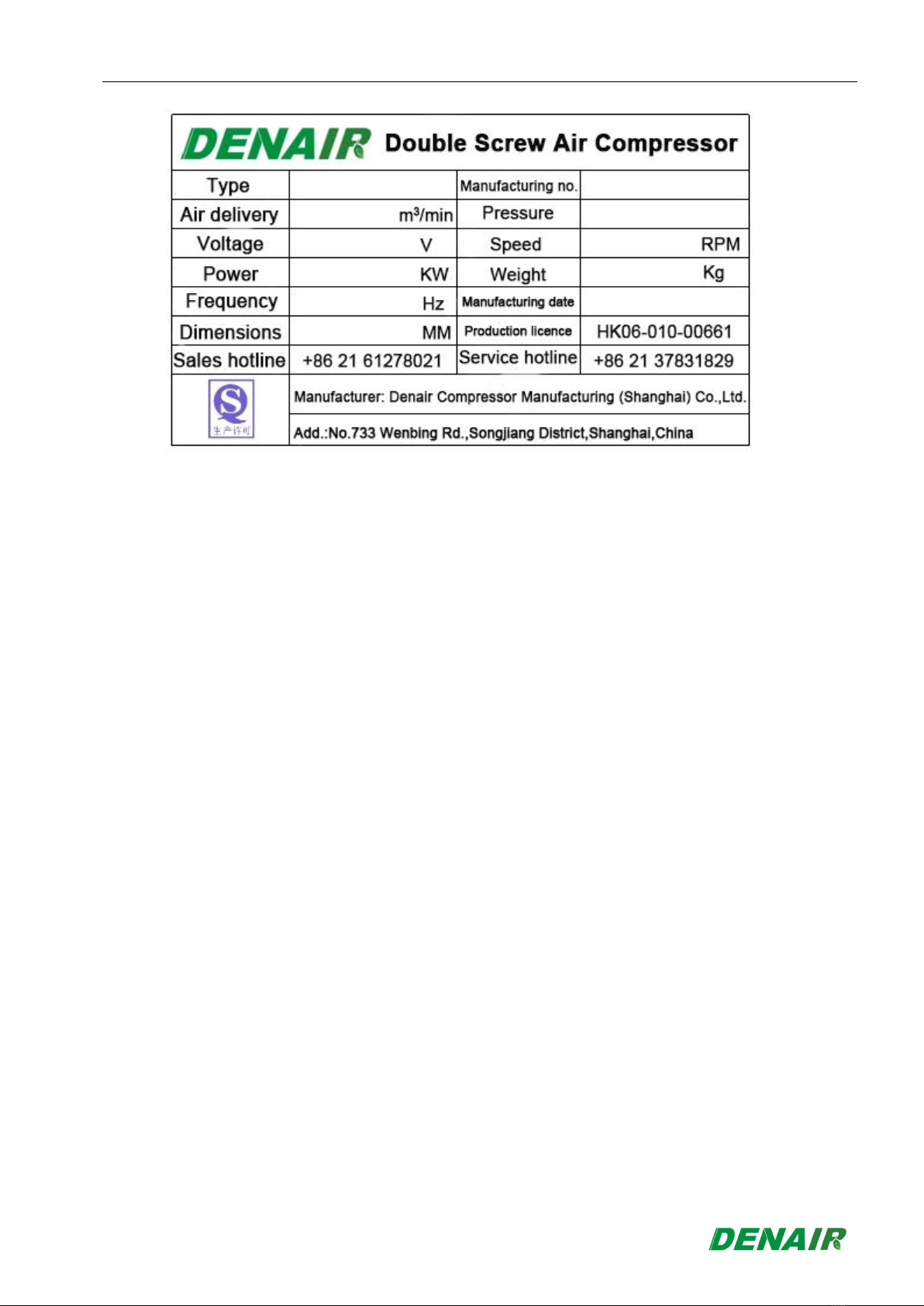
2.2 Check of Specifications and Model................................................................................... 2
2.3 Inspection of Accessories and Appearance................................................................... 3
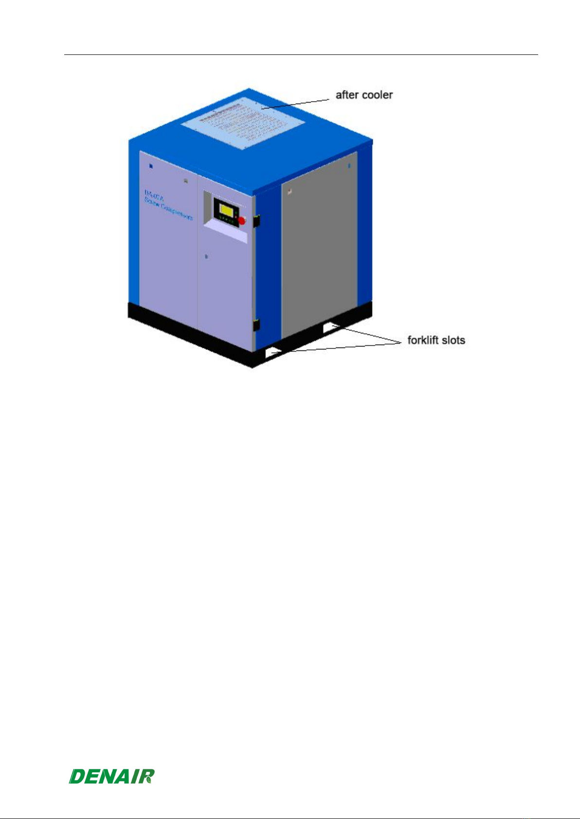
2.4 Handling Precautions............................................................................................................3
3. Installation..............................................................................................................................4
3.1 Environment Requirements.................................................................................................4
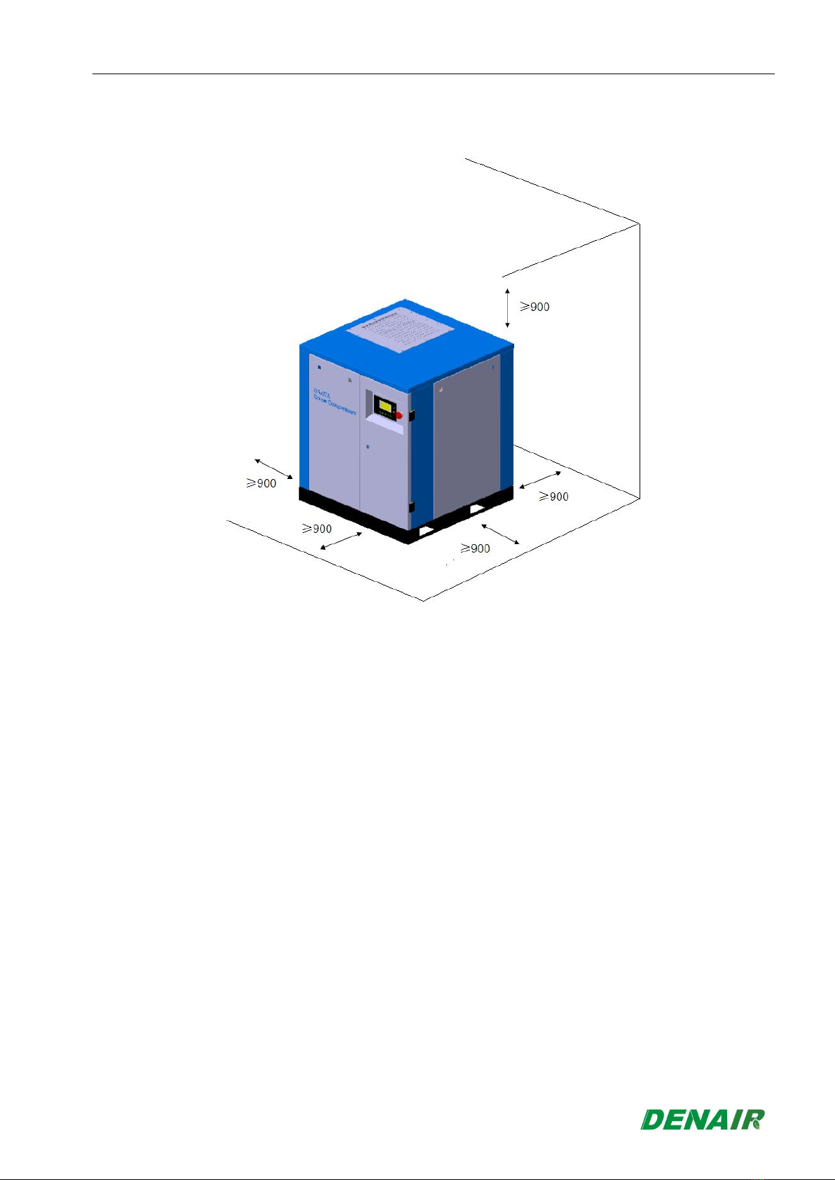
3.2 Installation Location Requirements.................................................................................. 5
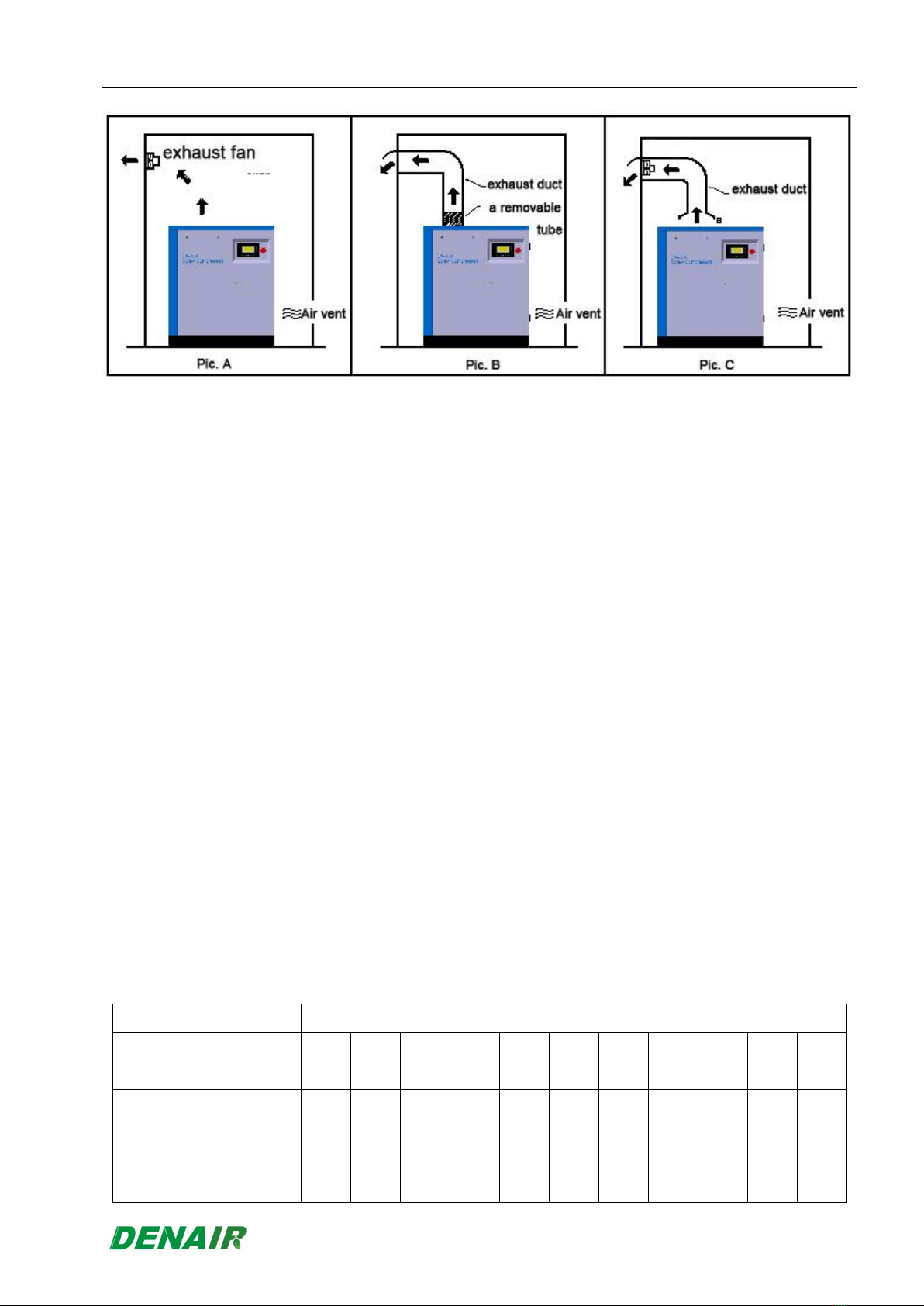
3.3 Ventilation and Cooling Requirements.............................................................................5
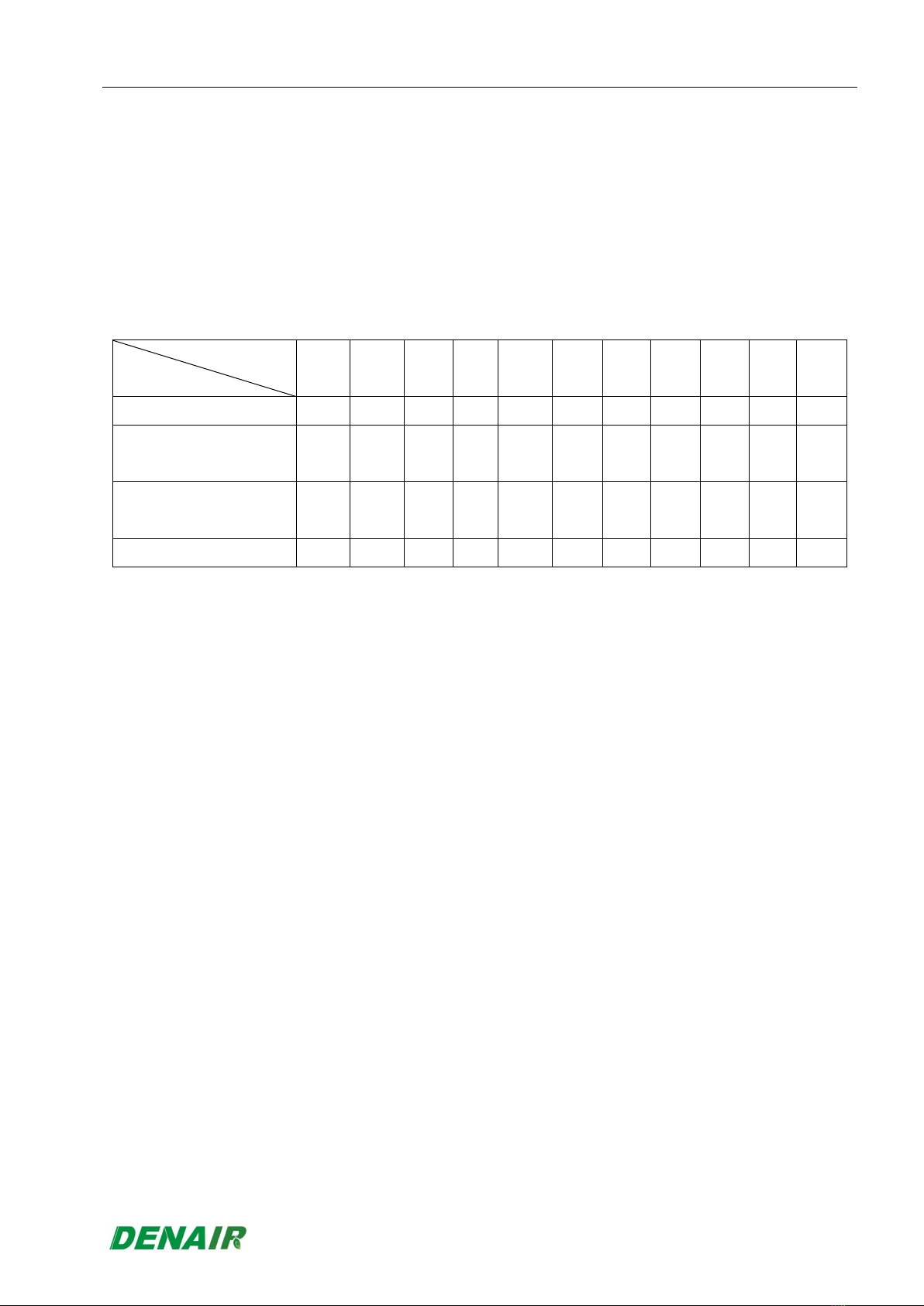
3.4 Selection Requirements for Air Rate of Ventilating fans............................................. 6
3.5 Warning..................................................................................................................................... 7
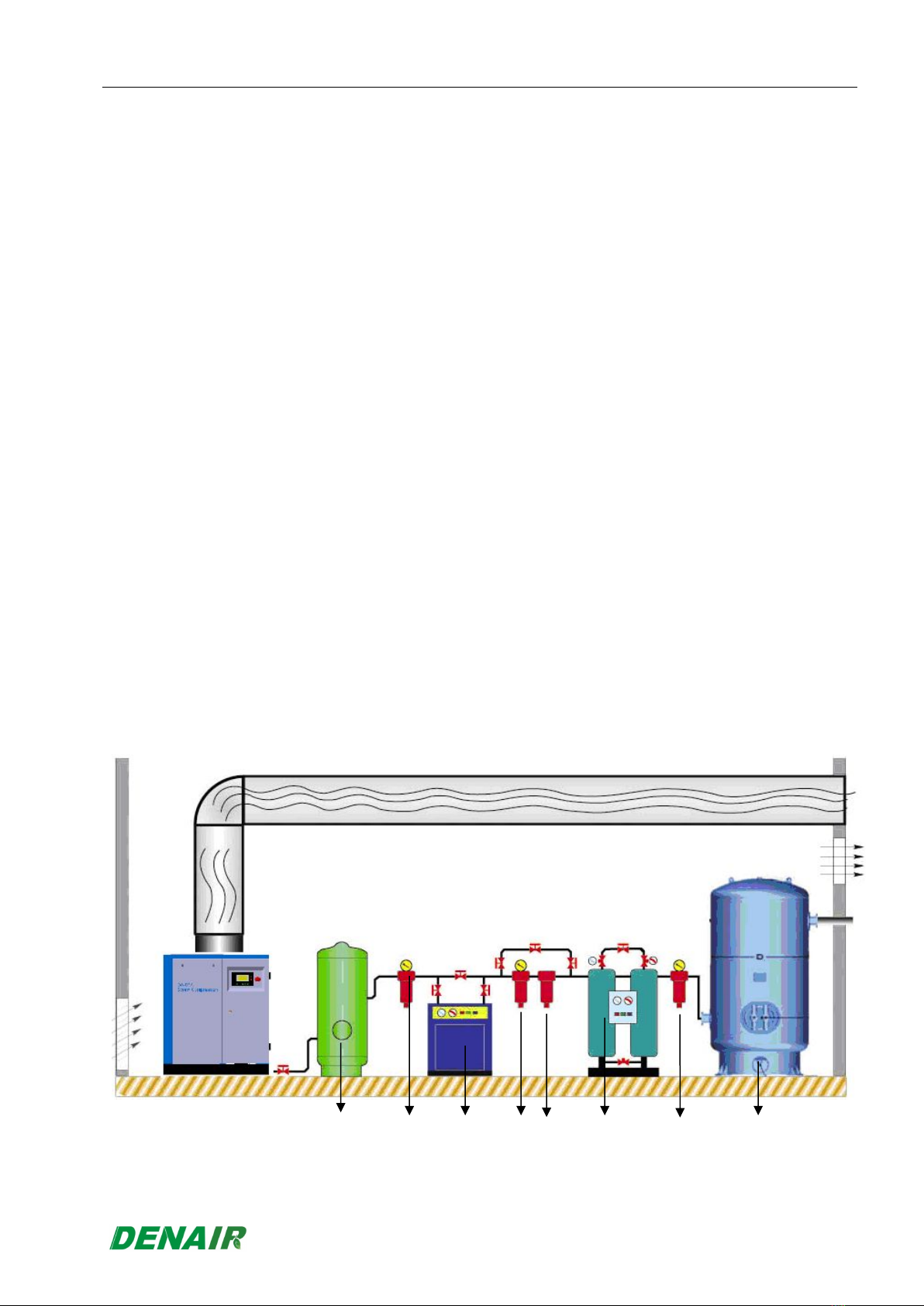
3.6 Suggestions for Pipeline...................................................................................................... 8
3.7 Electric Appliances Installation Precautions and Control System......................... 11
4. Introduction to the System............................................................................................14
4.1 Overall System......................................................................................................................14
4.2 Composition of the Compressor Unit.............................................................................14
4.3 Lubricating Oil System....................................................................................................... 15
4.4 Oil-gas Separation System................................................................................................ 15
5 Operation of Controller.................................................................................................. 16
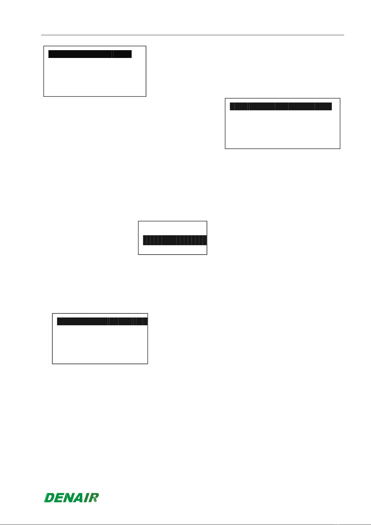
5.1 Key Description.................................................................................................................... 16
5.2 Contents of Controller........................................................................................................ 16
5.3 Contents of User Parameter..............................................................................................19
5.4 Schematic Wiring Diagram................................................................................................ 20
5.5 Control Operation................................................................................................................ 21
5.6 Warnings and Prompts....................................................................................................... 22
5.7 Safety Protection..................................................................................................................23
6. Function Description of System Components...................................................... 24
6.1 Air Filter.................................................................................................................................. 24
6.2 Inlet Valve............................................................................................................................... 24
6.3 Oil-gas Barrel........................................................................................................................ 24
6.4 Oil Separator..........................................................................................................................25
6.5 Safety Valve........................................................................................................................... 25
6.6 Pressure Maintenance Valve.............................................................................................25

DA Series Operation Manual
2
6.7 Rear Cooler............................................................................................................................ 25
6.8 Oil Cooler................................................................................................................................25
6.9 Oil Filter.................................................................................................................................. 26
6.10 Exhaust Temperature Sensor........................................................................................ 26
6.11 Pressure Sensor............................................................................................................... 26
7. Maintenance.........................................................................................................................26
7.1 Inspection and Update of Belt and Pulley..................................................................... 26
7.2 Air Filter.................................................................................................................................. 27
7.3 Lubrication of Motor Bearing............................................................................................28
7.4 Compressor Bearing........................................................................................................... 29
7.5 Air Compressor Lubricating Oil....................................................................................... 29
7.6 Oil Separator..........................................................................................................................29
7.7 Oil Return Pipeline............................................................................................................... 30
7.8 Engine Oil Filter.................................................................................................................... 30
7.9 Pipe Joint................................................................................................................................30
7.10 Inlet Valve..........................................................................................................................30
7.11 Pressure Maintenance Valve....................................................................................... 30
7.12 Safety Valve......................................................................................................................31
7.13 Draining Solenoid Valve................................................................................................31
7.14 Cooler................................................................................................................................ 31
7.15 Electric Insulation...........................................................................................................31
7.16 Periodic Inspection and Cleaning.............................................................................. 31
8. Safety Protection and Warning Device.....................................................................32
8.1 Motor Overload Protection................................................................................................ 32
8.2 Protection for Over-temperature of Exhaust................................................................ 32
8.3 Setting and Description of Other Protection and Warning....................................... 33
8.4 Failure Causes and Troubleshooting..............................................................................33
Annex I: Table of Cycles for Periodic Maintenance of Air Compressor............... 35

DA Series Operation Manual
1
1. Safety Precautions
Please carefully read this manual and operate based on the detailed instructions given in the
manual before installing and using the air compressor of the Company to avoid hazardous
events and prevent machines being damaged.
1.1 Electrical Safety
(1) Once power up the air compressor, the voltage generated will be very dangerous, therefore
only electricians and electrical engineers who are certified through national examinations
are allowed to perform the installation. The operators shall perform the safety operations in
strict accordance with the operating mode specified in this manual and national regulations
and safety code.
(2) Users and installation personnel shall provide earthing and installation protective circuit for
compressor units in accordance with national electrical standards.
(3) Each standalone compressor shall be installed with an exclusive breaker, which shall be
used with NFB with corresponding capacity, and see detailed configuration in the
instructions of Fig. 3.7.
(4) Make sure the power switch is turned off before any maintenance to avoid accidents. There
shall be a warning saying “No switching on” hanging on the power switch.
1.2 Driving Components
(1) Do not open soundproof enclosure before the air compressor is completely shut down so
as to avoid ganger.
(2) Any dismounting shall not be implemented until the motor and the fan have been
completely shut down and it is ensured that the power is cut off.
(3) Do not wear excessively loose clothes during maintenance to avoid accidents.
1.3 High Temperature and High Pressure
(1) For part of pipelines and components whose temperature may increase (a warning sign is
significantly affixed on the air compressor), touching is not allowed to avoid scald
accidents until it is confirmed to be completely cooled.
(2) There may be high pressure fluid in each component and pipeline of the air compressor, so
it shall be confirmed that the pressure of the unit has been completely discharged before
dismounting. The high pressure fluid shall be prevented from pointing to any person to
protect the person from been injured by the high pressure fluid.
(3) The compressed air provided by the air compressor is only for industrial purpose. Do not
breathe the air before it has been processed appropriately, or it will result in bodily injury,

DA Series Operation Manual
2
disease or death.
1.4 Unit Drainage
(1) The drain valves of oil-gas barrels of the unit and the system shall be open to drain
condensate water completely before starting up the air compressor, to ensure that the oil
products of the unit will not be emulsified and the compressor will not be stuck due to
deterioration of oil products.
(2) The post treatment device and the drainage function of devices shall be regularly
inspected to ensure the normal operation of the system.
2. Inspection and Handling
Please carefully read this chapter to ensure the rights of the customers. Handling shall be
implemented as per the manner mentioned in section 2.4 to avoid accidents and damage to the
unit.
2.1 Product Warranty of Compressors
The Denair Screw Air Compressors shall be delivered after conducting the strict quality management and
performance test. Except as otherwise noted (according to the terms of the product warranties), the
warranty period of the compressor shall be 18 months from the date of production of the compressor or
12 months from the date of formal commissioning of the compressor (which is due earlier).For any poor
quality or fault and damage caused by manufacturing reasons during the product warranty period, the
Company will provide free service for the products after confirmation. Any fault caused by, such
incontrollable factors as moving, striking, natural disasters and wars, or the operation and maintenance
not in conformity with instructions or without use of the consumables and oil products marked with Denair,
or the maintenance conduct by other person other than personnel of our company and servicemen of
service agency appointed by Denair, shall be excluded from the product warranty.
It is recommended that customers using Denair products should immediately inform the original Denair or
appointed service agency to troubleshoot the factors but not modify the system by yourself and force the
compressor to work, which may result in damages to the compressor, if there is abnormity of the
compressor caused by unusual condition of the unit
2.2 Check of Specifications and Model
Please check whether the nameplate specifications (see Fig. 2.1) of this air compressor conform to the
requirements of your order.

DA Series Operation Manual
3
Fig. 2.1
Note:
Model: prepared as per Denair’s in-plant model
Model specifications: prepared as per national standard JB/T2589-86
2.3 Inspection of Accessories and Appearance
Please check whether spare and accessory parts are all in readiness after receiving the air
compressor. If there is any quality problem, please contact us immediately. All Denair air
compressors shall be attached with the followings:
(1) One copy of operation manual;
(2) One copy of Warranty;
(3) Two keys to the door.
2.4 Handling Precautions
Please choose proper forklift or crane for handling based on the weight of the air compressor.
Please do not stand below the air compressor and keep at a safe distance as far as possible
during hoisting.

DA Series Operation Manual
4
Fig. 2.2
Notice: it is not allowable to place any items on the cooler over the metal plate, and the cooler
shall not covered to avoid tripping resulting from high temperature of the unit.
3. Installation
Please carefully read this chapter before installation to ensure the proper installation and
reliable operation of the air compressor.
3.1 Environment Requirements
(1) The air compressor shall be installed indoors where it is well ventilated and lit other than
the places with high dust, high humidity, etchant gas, metallic dust, direct radiation of
sunlight or direct rainwater.;
(2) The range of ambient temperature is 0℃~45℃.
(3) The air compressor shall be kept away from boilers and equipment which may emit heat,
and shall be equipped with awnings with favorable ventilation environment while being
installed outdoors.
(4) The ventilating fans around and over the air compressor shall set apart at least 900 mm
maintenance space (see Fig. 3.1).
(5) The altitude shall be less than 1000 m.

DA Series Operation Manual
5
(6) The relative humidity shall be less than 95%.
Fig. 3.1
3.2 Installation Location Requirements
The screw air compressor can be installed on any floor slab which may withstand the weight of the air
compressor without any special foundation, where the floor is smooth and horizontal. The air
compressor shall be fixed with foundation bolts; meanwhile rubber blanket shall be equipped to slow
down the vibration of the unit while being installed on the steel frame and mobile ships or vehicles.
3.3 Ventilation and Cooling Requirements
When installing the air compressor indoors or outdoors, good ventilation shall be ensure to
avoid heat short cycle or interaction effect from heat extraction of the machines, so the locations
of vent pipes, ventilating fans and compressors must be considered (there are typically three
ways, see Fig. 3.2).

DA Series Operation Manual
6
Fig. 3.2
Note:
(1) Fig. A: when the exhaust duct is not used for ventilation, refer to Table 3.1 Ventilation Rate (1) for the
recommended exhaust air rate of ventilating fans, and please install the ventilating fans as high as
possible.
(2) Fig. B: While using exhaust duct without installing the ventilating fans, the exhaust air rate of
the compressor and the pressure loss in the exhaust duct shall be calculated. When the pressure
loss is less than 20Pa, there is no need to install ventilating fans and the dismountable exhaust air
hose shall be directly installed at the air outlet of the compressor.(It is recommended that
customers should use the ventilation design of Fig. A and Fig. C best).
(3) Fig. C: When the pressure loss in the exhaust duct is greater than 20Pa, ventilating fans
shall be installed additionally where the distance between the exhaust duct and the air
outlet of the compressor shall be 200-300mm. Refer to Table 3.1 Ventilation Rate (2) for the
recommended exhaust air rate of ventilating fans. Pay attention to the exhaust air rate and
such conditions as the pressure loss in the exhaust duct and exhaust temperature increase
while choosing ventilating fans.
3.4 Selection Requirements for Air Rate of Ventilating fans
Table 3.1
Cooling method of the unit
Air cooling
Motor power of the unit
(KW)
5.5
7.5
11
15
18
22
30
37
45
55
75
Exhaust air rate (1)
(m3/min)
95
95
140
180
225
270
360
450
540
540
900
Exhaust air rate (2)
(m3/min)
50
50
50
90
90
170
170
170
240
240
340

DA Series Operation Manual
7
3.5 Warning
The compressed air and electricity are dangerous.
Prior to any operation on the air compressor, it shall be ensured that:
1 The power has been cut off with the switch locked and the notice plate hung;
2 All the pressure within the entire air compressor system shall be relieved.
(1) It is prohibited to dismount all kinds of caps and mounting and dismounting any joint or device while
the air compressor is running since the high temperature fluid and the compressed air in the air
compressor may cause severe personal injury and even death.
(2) It will bring voltage danger in the electric cabinet when starting up the motor of the air compressor,
therefore all installations shall be implemented in accordance with the accepted laws and
regulations. It shall be ensured that the system voltage can be cut off by disconnecting the switch
manually and the no-fuse switch shall be installed on the power supply line leaded to the air
compressor before running the electrical system. The personnel responsible for equipment
installation shall provide proper found connection, maintenance space and lightning arrester for all
electrical parts.
(3) The air compressor cannot be operated under the exhaust pressure which is greater than that
specified by the nameplate of the air compressor, otherwise the motor will overload which may
result in the tripping of the motor of the air compressor.
(4) The air compressor and auxiliary equipment shall be only cleaned with safe solvent.
(5) The manual stop valve (separate-type) shall be installed in the exhaust pipeline. If the safety valve
is installed between the stop valve and the air compressor, the safety valve shall provide adequate
capacity to release the maximum continuous air flow of the air compressor.
(6) Once any pressure is released through the safety valve due to over-high pressure in the system,
the reason for over-high pressure shall be promptly found out.
(7) If the lubricating oil of the air compressor flows into the air system of the plant, it may bring about
adverse impact. Such post treatment equipment as air dryer and secondary filter (oil-gas separator)
shall be chosen and installed properly to minimize any liquid additions in the air. It may be risky to
use plastic casing without metal cover for the filtration of pipelines. From a safety point of view,
metal casing shall be applied to all the pressure systems. For this purpose, it is recommended that
the air circuit system of the plant shall be re-inspected.
(8) The air tank of post treatment equipment of the air compressor shall be installed and maintained in
accordance with the regulations of Monitoring Specification for Pressure Vessel issued by Ministry

DA Series Operation Manual
8
of Labor of the People’s Republic of China.
(9) The indication stickers on the control panel and this operation manual shall be carefully read
according to each standard operation before starting up the air compressor.
(10) Various cover plates and casings shall be re-installed after completing daily maintenance.
Notice: when the shield plate of the unit is open, the air compressor shall not be started up.
Warning
Not taking such safety advice abovementioned may result in mechanical faults, property damages,
severe personal injuries and even death. Such factors as vibration, pulse, temperature, maximum
pressure, corrosion resistance and chemical resistance shall be considered for any air inlet pipe and
exhaust pipeline connected to inlet/outlet joints, and it should also be noted that there may be a little
lubricating oil in the compressed air generated by the oil air compressor, therefore reasonable allocation
and compatibility shall be ensured between exhaust pipeline and system post treatment device and filed
air demand.
3.6 Suggestions for Pipeline
3.6.1 Pipeline
The air cooler in the unit may sharply reduce the exhaust temperature below the dew point temperature
(under most environmental conditions), so there will be a large amount of condensate separating out. The
condensate valve (drainage device) shall be installed near the exhaust outlet of the air compressor and a
length of exhaust pipe shall be connected to the drainage device of condensate water.
Key point: The drainage device shall be inclined downward in order to work normally.
Notice: A length of drain pipe (transparent hose) shall be placed in the drain pipeline for ease of
inspecting the operation of the automatic drain valve. If the posterior pipeline further cools
the air, it may regenerate the condensate water. Therefore, the release valve and the
drainer of condensate water shall be installed at the lower place of the piping system.
Key point: The diameter of the exhaust pipeline shall be kept at least the same big with that of exhaust
connection pipeline in the casing of the air compressor. All pipelines and joints shall apply to
the maximum operating temperature of the unit, and the nominal pressure shall be kept at
least the same high with that of the oil-gas separator of the air compressor. It is important to
check over each joint dimension of the air compressor, and proper length and dimension of
the pipe, the number and category of the joints and valves shall be considered to reach the
maximum efficiency of the air compressor. It is important to comprehensively consider the
air system of the whole plant to ensure the safety of the entire system while installing new
air compressors. Condensate water will be necessarily produced in the air pipeline during

DA Series Operation Manual
9
air compression. Since vapor in the environment will be concentrated during inflating, it will
be cooled in the posterior air pipeline and become condensate water. The water in the
compressed air shall be drained in the whole pipeline system of nearly all the air
compressors, therefore every customer shall pay more attention to the above issues during
the use of the air compressor, the design of the pipeline system and daily maintenance. The
common problems caused by water are as follows:
(1) The water of the internal system of the air compressor may emulsify the lubricating oil and the air
compressor will be scaled and stuck.
(2) The water in the pipeline of the internal system of the air compressor will contribute to such poor
conditions as corrosion and scale formation and even worse situations.
(3) The instrument is obstructed,
(4) The control valve is stuck,
(5) There is a risk for air pipeline outdoors to freeze under low temperature environment,
Any problem above may lead to suspending production of part of or the whole plant. The compressed-air
dryers of post treatment equipment may reduce the concentration of vapor to prevent the air pipeline
forming liquid water. The combined use of the dryer and the filter, the after-cooler and the automatic drain
valve can effectively improve the air quality in the air system. Using two types of dryers, i.e. refrigerated
dryer and regenerative dryer can solve the problem of containing water in the outside air system of the
compressor. When the dew point requirement of the compressed air pressure is 1 ℃to 4 ℃, the
refrigerated dryer can be applied generally, however when it is required to keep the dew point
requirement of the pressure below 1℃, the regenerative dryer shall be used. Please contact local branch
or appointed distributor of Denair, which may help you choose the proper dryer.
Note: the rotary air compressor cannot be connected to a reciprocating air compressor system without
pulsation isolation device (e.g. sharable air tank).It is recommended that two different types of air
compressors should be connected to a common air tank via individual air pipeline.
A shut-off valve and a drain valve shall be provided for each air compressor in front of the sharable air
tank during parallel (selective assembly) installation of several air compressors in the plant.Notice:
(1) The drainage device shall be installed at backend of the air outlet of the compressor during
parallel connection.
(2) The drain valves of oil-gas barrels in the air compressor and air reservoirs of the
external system of the air compressor shall be opened to drain condensate water
completely before starting up the air compressor, to make sure that the oil products
of the unit will not be emulsified and the compressor will not be stuck due to
deterioration of oil products.

DA Series Operation Manual
10
(3) The drainage function of drainage devices of each post treatment device (equipment)
in the external system of the air compressor shall be inspected regularly to make
sure that the external system in the whole air compressor can operate normally.
3.6.2 Suggestions for Piping of Air Pipeline
(1) Based on the diameter of the air outlet pipe of the compressor, the air compression pipe with the
same or larger diameter shall be selected for the connection between the air outlet of the air
compressor and the air reservoir to reduce pressure drop.
(2) For ease of daily maintenance in the future, the outlet of the air compressor and air barrel shall be
connected with flange and one shut-off valve (close to the side of the air receiver) shall be installed
additionally. The air compression system shall be successfully isolated without exhausting the
system pressure and wasting the valuable energy for later maintenance.
(3) The requirement on flexibility of the pipeline shall be considered during implementing piping to avoid
resonance phenomenon of the pipeline as far as possible. The gradient of the air pipeline shall be
at least 1/100 so that the water in the air pipeline can be drained successfully.
(4) To prevent overmuch water in the pipeline being condensed and affecting the function of the
equipment, the dryer which can process blowing rate appropriately shall be usually installed behind
the air barrel to remove the water and produce the dry air as required.
See standard configuration of the general air system in the architecture of Fig. below.
Please contact Denair for different air qualities and their respective detailed configuration.
Fig. 3.7
1 2 3 4 5 6 7 8

DA Series Operation Manual
11
The numbers in the Fig. respectively indicate the following meanings:
1. Air receiver 5. Oil filter
2. Pre-filter 6. Adsorption drier
3. Refrigerated dryer 7. Ultra-filter
4. Ultra-filter 8. Air receiver
3.7 Electric Appliances Installation Precautions and Control System
3.7.1 Regulations on electric appliances installation preparatory measures
Before installing the electric appliances, it is recommended that you should review those safety
precautions abovementioned in this manual and find the nameplates of the air compressor and the motor
on the casing. The working pressure, the maximum exhaust pressure and characteristics and power of
the motor are listed on the nameplate. Make sure that the voltage of the circuit is consistent with that
specified on the nameplate of the air compressor. Open the electric cabinet and make sure that all the
electric appliances are properly and securely connected. Make sure voltage supplied by the control
transformer is proper. It shall be inspected for the secure connection of the motor and the control circuit.
Then reclose the electric cabinet.
Please refer to JB6213.5-92 national standard and the specifications in the table below to choose proper
specifications of the main power line, earthing wire and no-fuse breaker (NFB) for the air compressor to
ensure the safety of using the electric appliances. The safe current of the power line shall be set
under the condition where the ambient temperature is 35 ℃, the operating temperature is lower
than 55 ℃, the wire length is within 20m and shall be based on the 600V PVC wire. When the
power line fails to meet the settings above, the specifications of the power line shall be
increased to avoid failing to start up the air compressor due to over-limit of the voltage drop and
even bringing electrical hazards.
(1) It shall be better to separately apply one set of electric power system to the air compressor
but the parallel connection with other different power consumption system shall be
particularly avoided. If not, the air compressor will be overloaded, resulting in tripping of
the protective devices due to large voltage drop or imbalance of three-phase current,
therefore please pay more attention to the requirement for the air compressor with high
power.
(2) The correctness of the voltage shall be confirmed during the distribution of the air
compressor. The earthing wire of the air compressor shall be securely set up but not on the
air delivery pipe or the cooling water pipe directly.
(3) The air compressor shall connect an earthing wire to the ground to avoid danger caused by
electric leakage.
(4) The single cable shall not be too thick with the limitation of the dimension of the electric cabinet. If

DA Series Operation Manual
12
the sectional area of the power line is too large, it can be replaced with two or more power lines.
Each power line shall be three-phase balanced while using multiple power lines; otherwise it may
result in overheating cable and unbalanced synthesized voltage. The input supply voltage shall be
kept within ±10 %of the nominal voltage and the three-phase voltage difference shall be within
3%.There must be proper earthing wire connected with the air compressor, otherwise noise may be
connected to any control system in series and cause interference. If the earthing connection cannot
be improved, the values of temperature, current and voltage of the controller may fluctuate.
KW
Specifications
5.5
7.5
11
15
18.5
22
30
37
45
55
75
Full-load current (A)
15
18
25
35
41
49
66
81
98
119
167
Sectional area of the
power line (m m2)
2.5
2.5
4.0
8
10
10
16
25
35
50
70
Sectional area of the
earthing wire (m m2)
2.5
2.5
4.0
8
10
10
16
25
25
25
35
Breaker (NFB)
50
50
50
70
100
125
125
125
175
225
300
Note:
(1) The voltage specifications are 380V and 50/60HZ.
(2) When the earthing wire and the power line of the movable electric appliance are both
placed in the hose or cable, and the wire diameter of the electric appliance shall be the
same with the power line.
3.7.2 Driving motor
The driving motor of the air compressor shall correctly turn to the counter-clockwise direction when
seeing from the driving end. The inching time of the motor shall be as short as possible while inspecting
the turning of the motor of the air compressor. The button of “emergency shutdown” shall be pressed
promptly after pressing the startup button. If the turning direction of the motor is not correct, the master
switch shall be disconnected and the warning saying “No switching on” shall be locked and hung. Open
the electric cabinet, exchange any two joints (R, S, and T) on the starter, close and screw the electric
cabinet and re-inspect the turning direction of the motor.
3.7.3 Fan motor
Observe whether the fan exhausts air to the external unit, if the turning direction is not correct, the master
switch shall be disconnected and the warning saying “No switching on” shall be locked and hung. Please
exchange any two terminals on the contactor of the fan, close and lock the electric cabinet and inspect
the turning direction.
3.7.4 Control system

DA Series Operation Manual
13
(1) Start-up of the electromotor (pressure drop or Y running)
The inlet valve is fully cut off, the release valve is fully opened and the release solenoid valve is
closed during this period, meanwhile the inlet side is of high vacuum and the lubricating oil required
by the compression chamber and bearings is ensured by the difference between the vacuum in the
compression chamber and the atmospheric pressure in oil-gas barrel.
(2) Full pressure running of the electromotor (full pressure or △running)
The release solenoid valve is opened with power on after the control system switches to full pressure
running. When the release solenoid valve is closed, the pressure in the oil-gas barrel will gradually
rise. When the inlet valve is opened little by little, the pressure in the oil-gas barrel will rapidly rise so
that the inlet valve is fully opened and the compressor starts the heavy-load running. When the
pressure rises to a certain value, the pressure maintenance valve is fully opened and the air is
output.
(3) Heavy-load/no-load compressor
When the pressure persistently rises to the unload pressure settings, the release solenoid
valve starts to exhaust air. The inlet valve is closed so that the air enters from the bypass pipeline
and the pressure in the oil-gas barrel starts to discharge, meanwhile the pressure maintenance valve
is quickly closed to isolate the system pressure. The pressure in the oil-gas barrel is consistently
discharge to a certain valve, i.e. the no-load pressure to provide the pressure required by
lubricating oil circulation. At this time, the air enters from the bypass pipeline and is exhausted
by the release solenoid valve after being compressed by the compressor and this circulation shows
the no-load running. When the system pressure drops to the settings of the loading pressure,
the release solenoid valve will stop discharging, the inlet valve will be fully opened and the
compressor will be running with load for a second time.
(4) Shutdown
After pressing the STOP button, the release solenoid valve starts to exhaust air. When the
inlet valve is closed, the pressure maintenance valve will be closed, the pressure in the
oil-gas barrel will start to discharge and be isolated with the system pressure. The motor
shall stop running after the pressure in the barrel is exhausted to the no-load pressure and
the motor will be shut down after 20s.The pressure in the oil-gas barrel is consistently
exhausted to zero.
(5) High temperature tripping or motor overloading
When the exhaust temperature is greater than 105oC or the motor results in current
protective device actions due to overload, the power supply will be cut off which will

DA Series Operation Manual
14
immediately shut down the motor. Meanwhile the inlet valve is closed, the release valve will
be fully opened and the pressure maintenance valve will be closed and the pressure in the oil-gas
barrel will be exhausted to zero. Only when there are abnormalities during the running of the unit, it is
allowed to press the emergency shutdown, otherwise it may easily cause the system failure.
(6) Automatic stop system for overtime idling and reboot time setting
If the air used by the system reduces, the compressor keeps running at no-load conditions.
If the no-load running time exceeds the set time, the compressor will be automatically shut
down and the motor will stop running. When the air used by the system increases, the
system pressure will be reduced and the air compressor will automatically start to
supplement the air amount. For the time setting of shutdown caused by long-time no-load
running, another setting can be made by the controller of the air compressor. The air
compressor cannot be restarted up until five minutes after shutting down the motor.
3.7.5 Electrical circuit
The electrical control of the air compressor consists of two systems, including the internal
control system and the part of the startup disk. The startup disk is the Y-△startup control
used by general machineries. The control part is the electronic control. The electronic
control part will not be presented thoroughly in this chapter due to the complicated internal
circuit and control. If there is any loss or fault, please contact the customer service center of
Denair.
4. Introduction to the System
4.1 Overall System
The air compressor is driven by motor and the complete internal and external systems of the air
compressor are composed of the screw air compressor unit compressed by single stage and post
treatment device (air reservoir, dryer and filter) of the external system.
4.2 Composition of the Compressor Unit
The internal system of the air compressor unit is composed of the following main parts:
(1) Air filter
(2) Compressor
(3) Oil separator
(4) Pressure maintenance valve

DA Series Operation Manual
15
(5) After-cooler assembly
(6) Oil-gas barrel
The air enters the air compressor and flows through the inlet filter and the inlet valve. The compression of
the screw air compressor is generated by the meshing of a pair of helical rotors (one is male and the other
is female), which are respectively installed on two parallel shafts and in the high-strength cast iron casing.
The inlet and the outlet are located at either ends of the shell respectively. The slot of the female rotor is
meshed with and driven by the male rotor, and the exhaust end employs the bearing to prevent the rotor
axial floating. The oil-gas mixture is exhausted from the outlet of the main engine and enters the oil-gas
separation system which removes the most lubricating oil in the oil-gas separator. The lubricating oil will
flow back this system and enter the cooling system with the compressed air leaving a little PPM oil
content. The after-cooling system consists of a heat exchanger and drain device. The exhausted air after
cooling will condense much vapor contained in the air which can be removed in the posterior pipeline and
equipment terminal of the unit. The inlet valve is closed, the release valve is opened and the compressed
air enters in the inlet valve from the bypass pipeline during unload running.
4.3 Lubricating Oil System
The lubricating oil flows from the oil-gas separator and the oil-gas barrel to the inlet of the cooler and the
bypass port of the heat control valve under the pressure. The exhaust temperature of the compressor can
be controlled above the dew point by the heat control valve. When the air compressor starts up in cold, a
part of the lubricating oil will flow bypass the cooler. When the system temperature rises above the
settings of the temperature control valve, the lubricating oil will flow through the cooler. When the unit is
running under high temperature conditions, all lubricating oil will flow through the cooler. The outlet
temperature of the oil cooler of the air compressor can be controlled to eliminate the possibility of the
condensation of the vapor in the oil-gas separator. The temperature of the oil-gas mixture exhausted from
the unit can be kept above the dew point by maintaining high oil temperature. The lubricating oil with
controllable temperature enters the engine body through the oil filter under the constant pressure.
4.4 Oil-gas Separation System
The oil-gas separation system is composed of the oil-gas barrel with specially designed internal structure,
two-level gathered separator element and cooling oil recovery device. Basic operation principle of the
oil-gas barrel: The oil-gas enters from the inlet and impact the head of the oil-gas barrel to separate the
oil drops from the oil-gas mixture based on the state. The machinery impact can be applied to the oil-gas
barrel, which can separate oil drops with large diameter relying on its own gravity of the oil drop, which is
suitable for the oil drops with diameter greater than 1um.
When using the method of machinery impact, impacting the head by the oil-gas mixture may control the
oil molecules with a certain flow rate so that the oil drops can fall to the bottom of the oil-gas barrel during
discharging and the oil content discharged from the air can be reduced.

DA Series Operation Manual
16
Notice:
When the air compressor adopts water cooling type, please install a Y filter in front of the water
inlet of the air compressor additionally, otherwise the water cooling system of the air compressor
will fail to work.
5 Operation of Controller
Fig. 5.1
5.1 Key Description
Start - start key: the motor can be started by pressing this key.
Stop - stop key: the motor can be stopped by pressing this key.
Reset - reset key: reset by pressing this key.
Up - up arrow key: page up the menu by pressing this key.
Down - down arrow key: page down the menu by pressing this key.
Right - right arrow key: page down the menu by pressing this key.
Set - enter key.
5.2 Contents of Controller
5.2.1 State and display
The following interface will display when the unit is powered on.
The following interface will display five seconds later:
Welcome to use Denair
Screw Air Compressor
Exhaust temperature:** ℃
Supply pressure: 0.00MPa
Equipment has stopped
C001 local

DA Series Operation Manual
17
Please press “▼” and enter the following menu to select an interface:
5.2.2 View of operation parameter
Please press “▲” or “▼” and move the black scrollbar behind the “operation parameter” menu and the
sub-menu will pop up by pressing the key “Set”:
The following page will pop up by pressing “Right” again:
If it is the last level menu, there will be no black scrollbar on the interface. It will return to the previous
menu or main interface by pressing the return key “reset”. If the operation stops at a certain interface, it
will return to the main interface a few seconds later. The operation parameters such as runtime, runtime
for this execution, maintenance parameter, historical fault, date of production and field failure can be
observed and then return to the previous menu with the movement keys “▲” and “▼”, enter key “set” and
return key “reset” according to the above mentioned methods.
5.2.3 User parameter
a Method to modify parameter
The user parameters can be reviewed and modified with the above mentioned methods to view the
operation parameters, such as modify upper pressure limit, and the methods are as follows:
Press “▲” or “▼” to move the black scrollbar behind the “user parameter” and the “Right” key will pop up:
Operation parameter
User parameter
Manufacturer parameter
Current of main engine and fan
Cumulative runtime
Runtime for this execution
Maintenance parameter
Main engine (A) fan (A)
R: 0.0 0.0
S: 0.0 0.0
T: 0.0 0.0

DA Series Operation Manual
18
Repress the key “Right” to pop up:
If not continue pressing the key “Right”, the use parameters can be reviewed. Repress “Right” to pop up
the following interface which requires inputting the user password:
If not continue pressing the enter key, the use parameters can be reviewed. Repress enter key “Right” to
pop up the following interface which requires inputting the user password:
The flicker bit displays upon popping up this interface. The “▲” and “▼” turn to page up key and page
down key to modify the current bit while the “Right” turns to shift key to move the modified bit. Press “Set”
to confirm the input. The following interface pops up:
The prompts with a “*” on the upper right corner indicates that the interface has entered the user
parameter set condition.
The “▲” or “▼” turns back to the black scrollbar while the “ ” turns back to the enter key. Press the key
“Right” when the scrollbar locates at the “upper pressure limit”, then the flicker bit displays. The “▲” and
“▼” turn to page up key and page down key to modify the current bit while the “Right” turns to shift key to
move the modified bit. The flicker bit disappears upon pressing “Set”. The “▲” or “▼” turns back to the
black scrollbar while the “Right” turns back to the enter key. The other user parameters can be modified.
Press “Reset” to return to the previous menu or the main menu if no modification is required for other
parameters. The other parameters can be modified with the same method.
Pressure/temperature preset
Start-stop delay preset
Operation mode preset
Linkage parameter preset
2
Upper pressure limit 0.0MPa
Lower pressure limit 0.0MPa
Fan start temperature 00℃
Fan stop temperature 00℃
2
Loading pressure 0.0MPa *
Unloading pressure0.0MPa
Fan start temperature 00℃
Fan stop temperature 00℃
2
Input password
****
2
Table of contents
Other DENAIR Air Compressor manuals
Popular Air Compressor manuals by other brands

Panasonic
Panasonic DD51C78GBU6 Specification sheet

RIDGID
RIDGID GP90150A repair parts

Air Lift
Air Lift QuickSHOT 25572 installation guide

Central Pneumatic
Central Pneumatic 93657 Owner's manual & safety instructions

sunjoe
sunjoe 24V-AJC-LTE Operator's manual

pilotair
pilotair K17 Instructions and parts list

Central Pneumatic
Central Pneumatic 96469 Set up and operating instructions

Central Pneumatic
Central Pneumatic 69667 Owner's manual & safety instructions

ALLPOWER
ALLPOWER APC005 owner's manual

C-Aire
C-Aire S260R-LD1-115P owner's manual

airmaster
airmaster TIGER 11/510 Operation & maintenance instructions

Central Pneumatic
Central Pneumatic 93271 operating instructions