Denco CAIRplus User manual

OPERATION MANUAL
Modular Air Handling Units
CAIRplus®
Solutions with Maximum Flexibility

Table of Contents CAIRplus
2PR-2009-0096-GB • Subject to modifications • R8-10/2015
Table of Contents
1 Unit Type Code .................................................................................. 4
2 Safety and User Instructions ........................................................... 5
2.1 Availability of the operation manual ................................................................ 5
2.2 Scope of the operation manual ....................................................................... 5
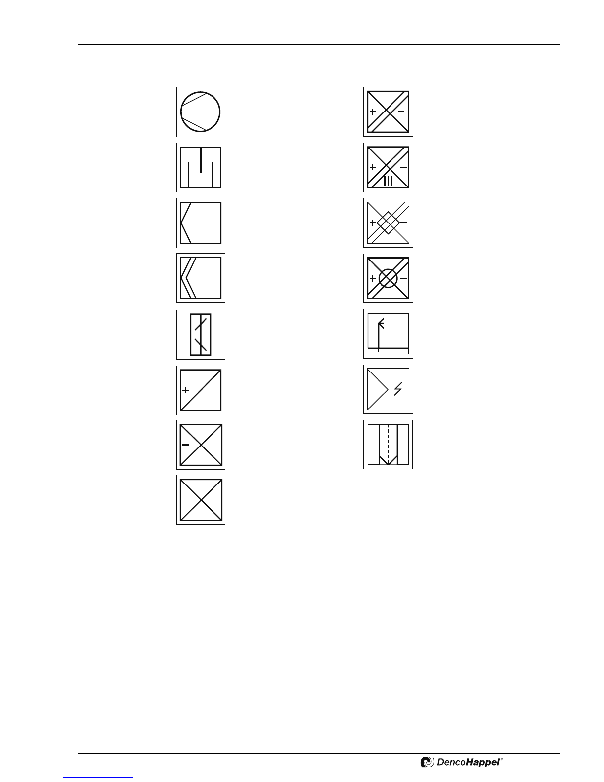
2.3 Symbols used .................................................................................................. 5
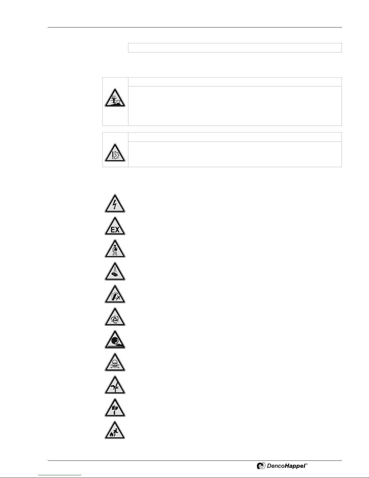
2.4 Labelling of safety instructions ........................................................................ 8
2.5 Used safety symbols ....................................................................................... 9
2.6 Safety-conscious work procedures ............................................................... 10
2.7 Proper use ..................................................................................................... 12
2.8 Safety devices ............................................................................................... 13
2.9 Modifications and changes ............................................................................ 13
2.10 Spare parts .................................................................................................... 13
2.11 Disposal ........................................................................................................ 13
2.12 Selection and qualification of personnel ........................................................ 14
3 Technical Description ..................................................................... 15
3.1 Performance scope ....................................................................................... 15
3.2 Technical Specifications ................................................................................ 15
3.3 Operating limits and range of application ...................................................... 15
4 Shipping and Storage ..................................................................... 19
4.1 Delivery ......................................................................................................... 19
4.2 Transport ....................................................................................................... 19
4.3 Storage .......................................................................................................... 22
5 Assembly ......................................................................................... 23
5.1 Unit placement .............................................................................................. 23
5.2 Assembling the unit ....................................................................................... 27
6 Installation ....................................................................................... 41
6.1 Requirements ................................................................................................ 41
6.2 Installing air-conveying components ............................................................. 41
6.3 Installing air-handling components with coil connections .............................. 42
6.4 Installing accessories .................................................................................... 48
7 Electrical Connection ..................................................................... 49
7.1 Requirements ................................................................................................ 49
7.2 Connecting unit ............................................................................................. 50

CAIRplus Table of Contents
PR-2009-0096-GB • Subject to modifications • R8-10/2015 3
8 Commissioning and Maintenance ................................................. 55
8.1 Routine cleaning and maintenance ............................................................... 56
8.2 Maintenance frequency checklist ................................................................... 58
8.3 General considerations .................................................................................. 61
8.4 Fan assembly and drives ............................................................................... 63
8.5 Filter assembly ............................................................................................... 68
8.6 Heater assembly ............................................................................................ 71
8.7 Cooler assembly ............................................................................................ 73
8.8 Cooling/heating coil ....................................................................................... 74
8.9 Heat pipe ....................................................................................................... 75
8.10 Liquid-coupled energy recovery coil .............................................................. 76
8.11 Plate heat exchanger ..................................................................................... 76
8.12 Rotary heat exchanger .................................................................................. 78
8.13 Humidifier assembly ....................................................................................... 79
8.14 Damper blades and shut-off dampers ............................................................ 79
8.15 Sound attenuators ......................................................................................... 80
8.16 Commissioning/maintenance of ECOTWINcool double-plate heat exchanger
with adiabatic cooling 80
8.17 commissioning/maintenance of integrated refrigerating systems .................. 80
9 Disassembly and disposal ............................................................. 83
9.1 Dismantling .................................................................................................... 83
9.2 Disposal ......................................................................................................... 83
10 Troubleshooting .............................................................................. 84
11 Appendix .......................................................................................... 85
11.1 Maintenance Log Book CAIRplus .................................................................. 85
– Original operation manual –
Copyright note
Disclosing, copying, distributing or taking any action in reliance on the contents of this document
is strictly prohibited without express prior consent. Violations entail liability for any damages or
other liability arising. All rights in relation to patents, utility patents or design patents are reserved.

Unit Type Code CAIRplus
4PR-2009-0096-GB • Subject to modifications • R8-10/2015
1 Unit Type Code
A128064VBVA
Unit part 2 *
Example:CAIRplusX1A#IHSEZ128064VBVA
Prefix General Unit part 1
Product family
Product group
Series
Unit design class
führungsklasse
Thermal separation
Casing
Type of application
Installation site
Air flow direction
Arrangement
Casing type
Function
Air flow
Unit width
Unit height
Material
Internal skin
Material
External skin
Material
Components
Material of profiles
CAIR
plus (air handling unit)
XSX Unit
1Standard without accessories
2Standard with accessories
3Special design
AAutomatic
TComplete
KWithout
#Standard
RStandard, in conformity with RLT 01 Directive
HHygiene
variant
EExplosion protected
IIndoor installation
AOutdoor installation
DCeiling mounting
WWall mounting
UUnderfloor installation
HHorizontal
VVertical
LL Form
SSingle
NSide by Side
ÜDouble-deck
HStraight-through
ESingle casing
KCombined casing
ZSupply air
AExtract air
Unit width (internal size in cm)
Unit height (internal size in cm)
VAluzink AZ 185
BRAL 9002 coated
2Stainless steel V2A (steel type 1.4301) or equivalent
4Stainless steel V4A (steel type 1.4571) or equivalent
BRAL 9002 coated
SCoated in special colour
VGalvanized
Lcoated
KCoated with enhanced corrosion protection
ANatural Alu
BRAL 9002 coated
* Unit part 2 – additional with arrangement types side-by-side, double-deck or straight-through

CAIRplus Safety and User Instructions
PR-2009-0096-GB • Subject to modifications • R8-10/2015 5
2 Safety and User Instructions
The CAIR units are constructed using the state-of-the-art technology and according to
recognized safety regulations. Operation is only allowed if the unit is in perfectworking
order given that current operation manual and safety instructions are observed and
potential hazards avoided! Otherwise failure to follow these instructions may result in
deathorinjuryto the user, thirdpersonsordamagetotheunit,connected units or other
equipment.Have all faults repaired by an authorized specialist without delay!
Consider the safety instructions provided by the manufacturers of individual compo-
nents!
2.1 Availability of the operation manual
This operation manual contains important instructions regarding safe and proper oper-
ation of the unit.
This operation manual applies to installation companies, operators, building techni-
cians, technical personnel or instructed persons as well as electricians.
This manual as well as the safety information of the manufacturer of the individual com-
ponents must always be available at the unit's installation site. When working on the
equipment, observe all instructions and precautions in the current operation manual, in
particular the chapter on safety.
2.2 Scope of the operation manual
This operation manual as well as the instructions of the manufacturer of the individual
components provide you the necessary information on the areas:
– Shipping and storage
– Mounting
– Installation and Electrical Connection
– Commissioning and Maintenance
– Disassembly and Disposal
2.3 Symbols used
The following symbols are used to highlight particular text sections in this operation
manual:
– This symbol is used to indicate normal lists.
•This symbol indicates instructions to follow.
9The result of an action is indicated with this symbol.
Danger symbols are specified in section "Labelling of safety instructions" on page 8.
Note!
Additional details on using the unit are specified here.

Safety and User Instructions CAIRplus
6PR-2009-0096-GB • Subject to modifications • R8-10/2015
2.3.1 Special warning and danger symbols
The following warning and instruction signs can be secured on the unit:
To connect - counter hold with a pipe wrench.
Attention: fire risk. Dust-laden filters are inflammable.
Before opening, use the main isolator to disconnect power.
Risk of injury. Wait until complete stop before opening.
Type sheet and assembly instructions attached to unit inside. Remove these doc-
uments before the unit commissioning.
Do not start up the fan against closed dampers.
Designation of unit in explosion-risk areas (according to 94/9/EG regulation)
Potential equalisation To equalize potentials the unit must be connected to an exter-
nal protective conductor at the designated points on the base frame.

CAIRplus Safety and User Instructions
PR-2009-0096-GB • Subject to modifications • R8-10/2015 7
2.3.2 Function signs
Fan or compressor indicating
air flow direction
Air heater/cooler with heat recov-
ery function
Air/water ECOFLOW
Sound attenuator in unit Air heater/cooler with heat recov-
ery function
Air/steam ECOSTAT
General air filter
indicating air flow direction Air heater/cooler with heat recov-
ery function
Air/air ECOPLAT
HEPA filter
indicating air flow direction Air heater/cooler with heat recov-
ery function
Air/air ECOROT
Opposed-blade dampers General air humidifier
Air heater air/water General controller
Air cooler air/water Droplet separator
Air cooler
Air/steam/refrigerant

Safety and User Instructions CAIRplus
8PR-2009-0096-GB • Subject to modifications • R8-10/2015
2.4 Labelling of safety instructions
To designate the safety instructions the following symbols and notices are provided in
appropriate places throughout this document:
2.4.1 DANGER - Death/serious irreversible injury
Indicates an extremely hazardous situation which will result in death or serious irre-
versible injury, if the safety instruction is not followed.
Example:
2.4.2 WARNING - Death/serious injury
Indicates a hazardous situation which can result in death or serious irreversible injury,
if the safety instruction is not followed.
Example:
2.4.3 CAUTION - Minor or moderate injury
Indicates a hazardous situation which can result in minor or moderate injury, if the
safety instruction is not followed.
Example:
Electrocution through hazardous voltage will lead to death or serious injury.
•Disconnect the unit from the power supply and ensure the power cannot be
switched back on.
•Ensure the unit is voltage-free and isolated, earth and short circuit the unit, cover
or shield off neighboring live components.
High concentration of refrigerants in the air can result in death or serious in-
jury!
High concentration of refrigerants in the air may have an anaesthetic effect and
cause unconsciousness. Prolonged exposure may cause irregular heartbeat and
sudden death. Very high concentration of refrigerant may cause suffocation by
reduced oxygen content in the surrounding air.
•You should therefore only work in an adequately ventilated environment, and
exercise due care and attention when carrying out the work.
•Wear protective clothing and, if necessary, an autonomous breathing apparatus.
Sharp edges can cause injuries!
Observe precaution when cleaning due to risk of cuts on thin and sharp edges.
•Wear protective gloves.

CAIRplus Safety and User Instructions
PR-2009-0096-GB • Subject to modifications • R8-10/2015 9
2.4.4 ATTENTION – Environmental or material damage
Indicates actions that can result in equipment or property-damage only accidents.
Examples:
2.5 Used safety symbols
ATTENTION
ATTENTION
Risk of environmental damage!
Heavilycontaminatedfilters can have a negative impacton production processes.
Depending on the filtered-out materials, contaminated filters are therefore classi-
fied as hazardous waste and must be properly disposed of according to the pre-
vailing guidelines and laws.
ATTENTION
Risk of damage to the unit!
If dampers are abruptly shut during unit operation, the unit can be damaged
beyond repair as a result of negative pressure or overpressure.
Electrical hazard
Explosive atmosphere
PERSONAL injury
Overhead loads
Risk of tipping
Rotating components!
Rotating storage materials
Toxic substances
Crushing of limbs
Sharp cutting edges
Inflammable materials

Safety and User Instructions CAIRplus
10 PR-2009-0096-GB • Subject to modifications • R8-10/2015
2.6 Safety-conscious work procedures
Observe the following instructions when carrying out installation, adjustment or repair
jobs:
•Wear suitable protective clothing during work, such as protective footwear, gloves,
safety goggles, etc..
•Avoid flame sources, especially burning cigarettes. Open flame sources and
smoking in the proximity to the unit are prohibited. Filters and especially used filters
can easily catch fire. Leaking refrigerant can catch fire andemit noxious substances.
When working within range of mains voltage:
When working in explosive atmosphere:
Scalding
Hot surfaces
Cooling
Environmental damage
Damage to the unit
Electrocution through hazardous voltage will lead to death or serious injury.
•Disconnect the unit from the power supply and ensure the power cannot be
switched back on.
•Ensure the unit is voltage-free and isolated, earth and short circuit the unit, cover
or shield off neighboring live components.
Life-threatening danger of explosive atmosphere!
The unit must only be operated under the conditions specified on the unit identifi-
cation plate.
Explosion-risk conditions may originate inside and/or outside the unit during its
operation as well as during dowmtime period. For this reason, it is assumed that
explosion-risk conditions are present, even if the unit is deactivated.
•Avoid using pro-inflammatory substances such as electrical tool and electronic
devices.
•Smoking and open flames within direct proximity of the unit are prohibited.
•Before starting any jobs - ventilate the interior and/or exterior of the unit!

CAIRplus Safety and User Instructions
PR-2009-0096-GB • Subject to modifications • R8-10/2015 11
For all kinds of work:
Jobs on the unit can only be carried out if
– all poles for the power supply are disconnected
– the unit is secured to prevent inadvertent energising (also refer to "Electrical haz-
ard")
– all moving components - in particular - fan impeller, motor, rotary heat exchanger,
controlandshut-offdampers– have cometoastandstill:wait at least 5 minutesafter
deactivating the unit
– the heat exchangers have cooled down to reach ambient temperature
Upon completion of jobs on the unit ensure that
– all protective devices are operating properly – for example, the fan safety devices
(door protection grille, contact guard) are locked
– no persons are present in danger areas.
Risk of personal injury!
No matter what kind of jobs are performed on the unit, there is always a risk of
cuts by thin sheet metal and heat exchanger fins. In particular, this aspect applies
when carrying out maintenance and cleaning work on the surfaces of heating and
cooling coils.
•Wear suitable protective clothing.
Before commissioning andafter maintenance of the unit thereisanincreased
risk of injury:
•Ensure that no persons are locked inside the unit. Walkable surfaces of the
unit are equipped with emergency levers on the interior side of doors. Smaller
units must provide a protection against inadvertent locking by using padlocks
on the door stop.
An operating unit poses a risk of injury:
– Danger of impacts by opening doors arranged on the discharge side
– Danger of crushing resulting from negative pressure applied to doors on the suc-
tion side
– Danger resulting from rotating parts such as fans etc.
– Danger of hot surfaces and/or media
Units equipped with coolers with a refrigeration circuit pose additional risks.
•Observe all the safety notes contained in Chapter "commissioning/maintenance
of integrated refrigerating systems" on page 80.
ATTENTION
Risk of damage to the unit!
If dampers are abruptly shut during unit operation, the unit can be damaged
beyond repair as a result of negative pressure or overpressure.

Safety and User Instructions CAIRplus
12 PR-2009-0096-GB • Subject to modifications • R8-10/2015
2.6.1 Handling refrigerants (only for units with integrated refrigerating system)
According to DIN EN 378 Part 1 the R-134a and R-410A refrigerants belong to A1
group. Refer to the unit identification plate for data and charge volume of a particular
refrigerant.
Observe the usage details in accordance with EC regulation 842/2006.
Features of applicable refrigerant types:
– Non-combustible
– No direct toxic effect
– Colorless and odorless
– Heavier than air
– Contains fluorinated greenhouse gases as defined by the Kyoto protocol
– Ozone-depleting potential OPD: 0
– Greenhouse potential GWP: R-134a: 1300, R-410A: 1980
– Water hazard class WGK 1, with a slight risk to water
•Wearappropriateclotheswhenperformingjobswithrefrigerantsandintheproximity
to a refrigeration circuit, e.g.
– Sealing protective goggles
– PVA or leather gloves
– Protective clothes for entire body
– If necessary, an autonomous breathing apparatus
First aid First aid measures directly after or during contact with refrigerants:
– Ensure your own protection against leaking refrigerant.
– Under all circumstances - call a doctor or and/an ambulance.
– Remove clothes contaminated by the refrigerant.
Inhalation Additional measures after inhalation of refrigerants:
– Take the injured person to a well-ventilated location.
– Ensure that the injured person is in a stable lateral position.
– Consumption of food and beverages must be avoided.
– If the injured person collapses or loses consciousness – perform mouth-to-mouth
respiration.
Skin contact Additional measures after skin contact with refrigerants:
– Rinse the affected body parts using lukewarm water for at least 15 min.
Eye contact Additional measures after eye contact with refrigerants:
– Do not rub your eyes.
– Remove contact lenses if you have any.
– Rinse your eyes with lots of water.
2.7 Proper use
The CAIRplus units are only intended for handling air and performing the following
jobs:
– filtering normally polluted air
– filtering air in cleanroom applications (special cleanroom design)
– air heating and/or cooling
– humidifying and/or dehumidifying of air
– heat rejection or heat recovery
– filtering and treatment of air with a high moisture content and/or with high levels of
contamination (special models, for example for swimming pool or kitchen exhaust
applications)
– or combination of the above-mentioned functions.

CAIRplus Safety and User Instructions
PR-2009-0096-GB • Subject to modifications • R8-10/2015 13
Properusealsoincludesobservanceof the operationmanualand instructionsfrom the
manufacturer of the individual components, as well as the inspection and maintenance
intervals stipulated by DencoHappel.
Improper use Any use other than that described above is considered improper. If necessary, check
if your units are suitable for your intended purpose and application. The manufacturer/
supplier is not liable for any damages arising from improper use. The user alone bears
the risk.
Misuse particularly includes:
– Conveying any other gases except air
– Conveying steam or water
– Coarse filtering and/or filtering any other media except air
– Chopping up or reducing size of materials
– Drying out clothing
The unit is not suitable for handling abrasive media.
It is not allowed to operate CAIR units:
– in explosion-risk areas, unless units are certified for use in these relevant areas (air
handling units meeting special explosion-protection requirements in accordance
with ATEX Guideline 94/9/EG)
– in rooms with conductive dust
– in rooms with strong electromagnetic fields
– in rooms with aggressive atmosphere that may attack plastics or cause corrosion
(especially in atmosphere where zinc is particularly susceptible to corrosion).
– CAIR units must not be accessible to the general public.
2.8 Safety devices
Depending on the unit equipment, the following components are secured:
– Padlock in the door-stop device (TAS) on each door
– Locks of switch cabinet
– The panels and doors with lockable handles
– Fan chambers are secured by door protection grilles
– V-belt drives are secured by belt guards
Ensure by others on site that the contact protection for intake and discharge fittings is
provided.
2.9 Modifications and changes
Changes, alterations or modifications of the unit are not allowed. Tampering with the
unit or its misapplication will invalidate the CE conformity and void warranty.
If delivered units are disassembled by others on-site, the factory warranty is rendered
invalid. In this case professional services by DencoHappel should be arranged in
advance.
2.10 Spare parts
Only original DencoHappel spare parts are allowed, since DencoHappel is not liable if
third-party spare parts are used.
2.11 Disposal
Equipment, operating supply materials, components and filters must be disposed of
according to the material type in a safe and environmentally friendly manner.

Safety and User Instructions CAIRplus
14 PR-2009-0096-GB • Subject to modifications • R8-10/2015
2.12 Selection and qualification of personnel
Ensure thatevery person working onthe unit hasread andunderstoodentire operation
manual. Please read this document fully before commencing any work, and not while
performing a task.
All jobs must only be carried out by qualified licensed staff or other individuals with
proper professional training and experience in the following areas:
– Occupational health and safety regulations
– Accident prevention regulations
– Directives and recognized codes of practice
All jobs with the refrigeration circuit shall be performed only by certified and licensed
staff in accordance with the valid EG Regulation 842/2006 Article 5, EG Regulation
303/2008 Article 4 and 5 as well as "Ordinance on climate protection against changes
caused by release of certain fluorinated greenhouse gases" Article 5, passed by the
German parliament.
All skilled staff must be able to assess the entrusted work and must be able to recog-
nize and avoid all associated dangers.

CAIRplus Technical Description
PR-2009-0096-GB • Subject to modifications • R8-10/2015 15
3 Technical Description
3.1 Performance scope
CAIRplus units are generally used for energy-saving supply-air and extract-air indoor
ventilation. Due to their modular design, units can be configured individually to meet
particular air-handling requirements and specifications. The transported air can be fil-
tered, heated, cooled, humidified or dehumidified, depending on the application for
each case. The aim is to meet the customer specifications concerning required air vol-
ume and conditions.
CAIRplus units are used at a central point for comfort air conditioning on commercial
and industrial premises for the transportation and treatment of “normal” air. The units
can also be manufactured in a customized design and adapted for cleanroom and
hygiene applications. CAIRplus units meeting explosion-protection standards and
complying with the ATEX 94/9/EG Directive are clearly designated and marked. These
units are supplied with an additional operation manual that must be read and consid-
ered.
A range of unit components are available for energy-saving purposes: rotary heat
exchangers,plateheatexchangers,heatpipes andliquid-coupledheat exchangersfor
the recovery of heat and the partial recovery of moisture as well.
Units are performed in different sizes and have various capacities. Depending on the
applicationforeach case, CAIRplus units are designed for vertical or horizontal air flow
and are arranged as double-deck, side-by-sideand straight-through models. Units can
be installed indoors and outdoors.
Thanks to the modular design of the CAIRplus, units ship as complete assemblies or
sub-assemblies that can pass through the available on-site openings in the course of
installation. CAIRplus units are also suitable for the modernization and retrofitting of
existing buildings due to the number of available unit sizes and a unit ordering option
providing for delivery in small shipment units.
3.2 Technical Specifications
Refer to the order-related documentation for the specific configuration of your CAIR-
plus unit (unit drawing with dimensions and technical data).
3.3 Operating limits and range of application
– Please carefully observe the unit type plate and the operation manuals for the sup-
plied accessories.
– Please refer to the accompanying documentation or technical specifications provid-
ed in the unit-layout software for the operating limits or related restrictions of individ-
ual built-in parts and components.
– The unit warranty is only valid if the specified materials are adhered to when units
are used in corrosive or aggressive environments!
– In process-air applications, consider the tolerance-related differences in aerody-
namic values!
– In frost-risk cases, use antifreeze agents for heating and cooling media.
– Operating limits for CAIRplus special/customized units are available on request.

Technical Description CAIRplus
16 PR-2009-0096-GB • Subject to modifications • R8-10/2015
3.3.1 Ambient conditions
Outdoor air
from -25 °C to +60 °C
Extract air from 0 °C to +80 °C
Air humidity depending on temperature max. 18 g/kg of dry air
Max. operating pressure
and temperature Heating/cooling coil 16 bar / 90 °C
Minimum operating tempera-
ture Heating/cooling coil 6 °C
Notice on extreme
conditions! In addition to the air temperature/air humidity of the transported medium, the temper-
ature/humidity of the ambient air is also critical. Environmental factors such as proxim-
ity to sea or ocean must be taken into account when selecting material quality.
Different ambient conditions apply for integrated refrigerating unit.
3.3.2 Permitted storage conditions / permitted air condition for uninstalled units
Air temperature -10 °C to +50 °C
Air humidity Store units in a dry, non-condensing atmosphere
3.3.3 Supply voltage
The required supply voltage is specified in the order-related documentation, e.g. AC
230 V/50 Hz (1 phase) or AC 400 V/50 Hz (3 phases).
3.3.4 Condensation limits
Please pay due attention to condensation limits!
The following diagrams illustrate condensation limits depending on temperature and
relative humidity at the installation site - for series CAIRplus SX M and CAIRplus SX K.
The diagrams are based on normal air values and are calculated using a model box.
The given values are approximate figures and can not be used as a guarantee for
avoiding condensation. Depending on different casing components, deviations are
possible.
Note on extreme conditions!
In addition to the air temperature/air humidity of the transported medium, the tem-
perature/humidity of the ambient air is also critical. Observe the condensation lim-
its.

CAIRplus Technical Description
PR-2009-0096-GB • Subject to modifications • R8-10/2015 17
Read example:
With ambient conditions of 27 °C and 60 % relative humidity, air temperature in unit
may amount to -1 °C without formation of condensate.
CAIRplus SX K
= without thermal separation Condensation diagram for kb-value: 0.5
CAIRplus SX M
= partial
thermal separation
Condensation diagram for kb-value: 0.62
Air temperature on unit external side in °C
Air temperature on unit internal side in °C
Relative humidity on unit external side in %
Air temperature on unit external side in °C
Air temperature on unit internal side in °C
Relative humidity on unit external side in %

Technical Description CAIRplus
18 PR-2009-0096-GB • Subject to modifications • R8-10/2015
Air temperature on unit external side in °C
Air temperature on unit internal side in °C
Relative humidity on unit external side in %

CAIRplus Shipping and Storage
PR-2009-0096-GB • Subject to modifications • R8-10/2015 19
4 Shipping and Storage
4.1 Delivery
CAIRplus unit can ship as a single piece or multiple individual shipment units. Delivery
is done on transport pallets.
•When the unit is delivered, check that the shipment is correct according to the
dispatch note, and also check for completeness.
What steps should you
should take in the event of
shipping damage?
The exterior of the packaging is damaged
1 Unpack the equipment in the presence of the truck driver andhave him confirm the
damage on the shipping order.
2 Inform the DencoHappel Sales Company immediately.
Exterior packaging is OK, contents are damaged.
1 Once you have established the extent of the damage, report the damage to the
DencoHappel Sales Company in writing.
2 Take photographs of the damaged parts.
3 Possible shipping damage must be reported no later than 4 days after delivery.
It will not be possible to process claims if the above-mentioned points are not fulfilled.
In both cases, consult the DencoHappel Sales Company before installing the units.
4.2 Transport
Notice!
Consider instructions relating to the procedures in case of shipping damage pro-
vided on the unit packaging or in dispatch documents!
Danger due to overhead loads – risk of grave injuries or death!
•Never stand beneath suspended loads, since there is always a risk that the lifting
gear, tackle, ropes or slings are faulty or damaged.
•Use only the lifting lugs provided by DencoHappel!
•Make sure that equipment is firmly seated before lifting it.
Risk of personal injury and equipment damage!
Due to a high center of gravity, some equipment can tend to tip over and cause
damage to persons and property.
•When transporting the unit, careafully observe its behavior and do not get near
any possible hazardous areas.
Notice!
•Transportthe unit only in its original packing. Onlyremovethe original packaging
just before installation.
•Remove the pallet before lifting the unit modules at the lifting lugs / transport
gear.

Shipping and Storage CAIRplus
20 PR-2009-0096-GB • Subject to modifications • R8-10/2015
•For safety reasons, wear protective clothing when lifting or transporting the unit.
•Before lifting or shipping the unit, make sure that all doors, dampers and panels are
fixed and secured.
•Only use lifting gear with sufficient load-bearing capacity.
•Never use damaged lifting equipment.
•Ropes/chains must not be knotted and/or be exposed to sharp edges.
•Only use ropes/chains of the same length.
•Use only the lifting lugs provided by DencoHappel!
•Move the unit carefully without jerky movements.
•Do not set the unit down abruptly or bump it.
4.2.1 Lifting the unit – lifting lugs on roof (provided with shipment units weighing up to 1500 kg)
•Lifting lugs may only be used for lifting.
•Do not use lifting lugs for lateral loads (pulling of unit on
sides).
•The suspension angle must be between 70° and 110° (see
fig. 4-1).
•Lifting lugs may only be used once.
•Do not use lifting lugs for permanent suspension of units.
•Do not lift any other loads together with the shipment unit.
•Withunitsforoutdoorinstallation,ensurethattheroofsheets
are not damaged by the lifting gear.
•The maximum lifted weight of the shipment unit
may not exceed 1500 kg.
•Use all four eyeplates to lift the shipment unit.
Fig. 4-1: Lifting lugs for shipment units weighing up to 1500 kg
Angle range
70 - 110°
Table of contents
Popular Air Handler manuals by other brands

BLAUBERG
BLAUBERG KOMFORT EC Series user manual

CIAT
CIAT Floway Access 1000 instruction manual

Frico
Frico AGS5000 Original instructions

Genex
Genex HW(R)130 installation manual

Salda
Salda SMARTY R V MOUNTING AND INSTALLATION INSTRUCTION

Bryant
Bryant 524J Series Installation, Start-Up and Service Instructions

Vents
Vents VUT 300 V2 MINI EC A2 user manual

Salda
Salda RIS V EKO 3.0 1200VEL MOUNTING AND INSTALLATION INSTRUCTION

System air
System air Topvex TR09 HWL Installation instruction

System air
System air Danvent TIME Annex for the user manual

System air
System air MAXI 1500 installation instructions

System air
System air Topvex SoftCooler SR09 Operation and maintenance instructions