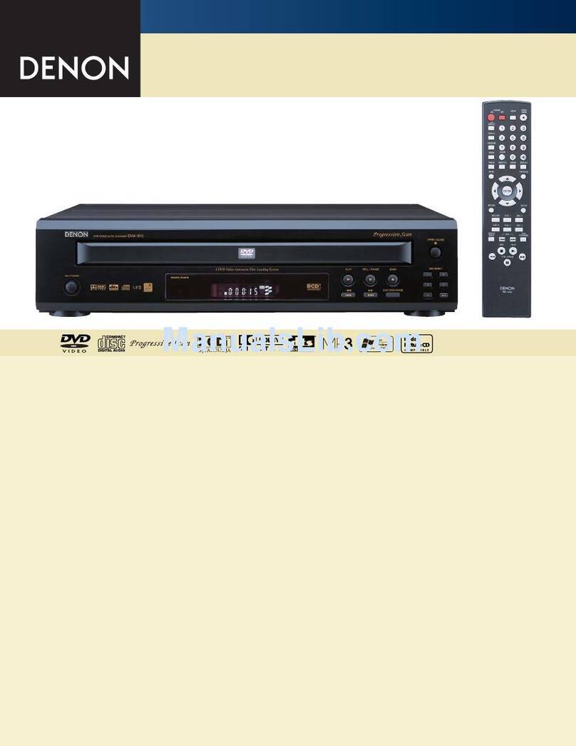
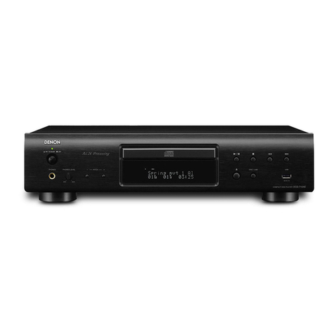
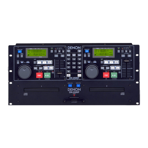
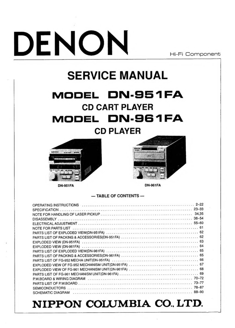
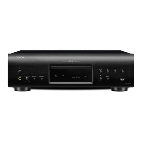
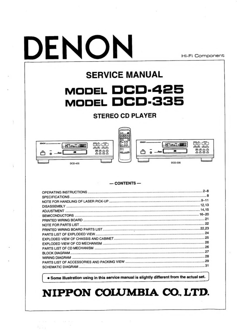
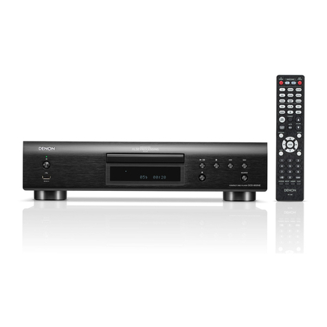
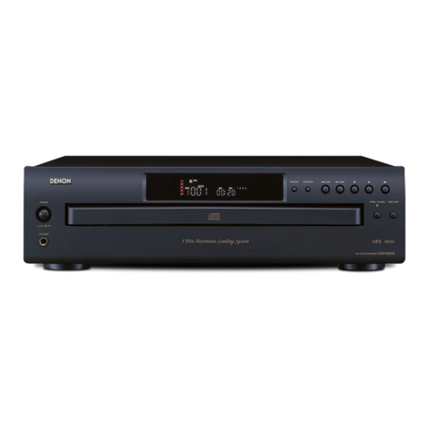
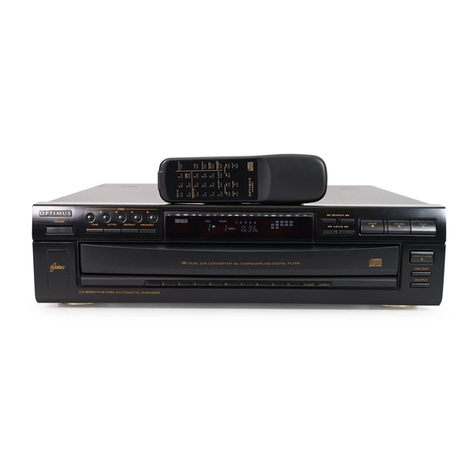
Denon DCD-1500 User manual

DENON
_......
SERVICE
MANUAL
STEREO
CD
PLAYER
MODEL
DCD-
1500
NIPPON
COLUMBIA
CO.
LTD.

TABLE
OF
CONTENTS
|
FEATURES?
fin
es
cibehes
lo
neu
Soe
eRe
disuse
ehetetecs
pobiadvode
02
SPECIFICATIONS!
fe:
nsce-c
syn
Geltediast
OS
tk
Pal
DUD
Re
ea
a
uae
eae
eae
eS
ue
NAMES
AND
FUNCTIONS
OF
PARTS
........0-.000-020e
ee
ee
ee
es
sie
RNa
Be
48~6
NOTE
FOR
HANDLING
OF
LASER
PIC-UP.
000.0...
cee
eee
eee
teeta
dhe
Ais
ata
7~8
HANDLING
CONNECTION
AND
SAFETY
INFORMATION
FOR
THE
KSS-121A
OPTICAL:
PICKUP,
6:
ts
once
tacdts
Mas
atenhe
Ua
Wd
ce
Ove
oe
eatenen
scien
oh
9
DISASSEMBLY
........2000000
005
Bsn
sae
aheGNEA
pI
ee
nhs
cee
eee
10~
12
ADJUSTMENT
OF
MECHANISM
UNIT...
0.000000
ccc
cece
eee
eee
cere
eee
eeeeees
13
MAINTENANCE
AND
ADJUSTMENT
PROCEDURE.
...
0.0.0.0...
0
0
cece
eee
eee
ee
13
~
20
FUNCTION
OF
IC
TERMINAL.
.........-.
ara
ie
ioc
epee
and
eaten
fy
ste
See
Rien
este
ers
21
FUNCTION
OF
SUB
CODE
OUTPUT
TERMINAL.
00002002000
cee
cece
ee
cee
ene
enee
22
TROUBLESHOOTING.
.......
000
eee
e
ccc
ee
c
ee
tee
cece
enn
e
eee
een
eens
23
~
27
PARTS
LIST
OF
PW.
BOARD
.....
0.00.0
c
ce
ccc
ce
cece
eee
e
eee
eee
eeeteeaee
28
~
31
PARTS
LIST
OF
EXPLODED
VIEW
00.0.0
0c
cece
cee
ce
ee
sence
eee
ee
eneees
32
EXPLODED
VIEW......
so
ettccpsid
Reals
Pele
She
tare
el
Oe
ia
vrs
sredisudeke
asi
uee
33
EXPLODED
VIEW
OF
FG-500
MECHANISM
UNIT...
0.0.00
c
ee
cee
cece
eee
eens
34
PW.BOARD
,......
0.00
cece
ccc
ce ee
cert
bee
eeedeeneenaeee
ee
35
~
37
WIRING
DIAGRAM
«6
2a
cnn
k
cor
eo
Seat
hg
Aicoed
Pee
dada
dhanwadetawg
we
nee
38
SEMICONDUCTORS.
....
0c
c
cc
eee
ec
e
cc
eee
dente
tee
e
eset
ec
ee
nee
eeneeees
39
WAVEFORMIN
THE
CIRCUIT
1.0.
2
ee
ee
te
ee
te
eee
eee
40
SCHEMATIC
DIAGRAM
..
00.0
cc
ec
cece
cette
eee
c
tee
eet
e
ete
eeeenees
4)
FEATURES
The
DCD-1500
compact
laser
disc
player
utilizes
a
unique
DENON
Double
Super
Linear
Converter
which
-
prevents
deterioration
of
sound
quality
in
the
PCM
playback
system,
assuring
accurate
reproduction
of
sound
recorded
on
compact
laser
discs,
in
the
studio
or
in
live
sound
production
areas.
The
parts
for
this
high
pertormance
disc
player
have
been
selected
with
careful
discrimination,
to
produce
realistic
playback
of
the
full
musical
production.
:
>

eer
SPECIFICATIONS
AubDIo
No.
of
channels:
Frequency
response:
Dynamic
range:
Signal-to-noise
ratio:
Harmonic
distortion:
Separation:
Wow
and
flutter:
Output
voltage:
DISCS
Playing
time:
Diameter:
SIGNAL
FORMAT
Sampling
frequency:
Quantization:
Transmission
bit
rate:
PICKUP
System:
Lens
drive
system:
Light
source:
Wavelength:
GENERAL
CHARACTERISTICS
Power
supply:
Power
consumption
Dimensions:
Weight:
FUNCTIONS
AND
DISPLAY
Functions:
Display:
Other
functions:
REMOTE
CONTROL
UNIT
Remote
control
system:
Power
supply:
External
dimensions:
Weight:
ACCESSOREIS
2
channels
5
~
20,000
+0.3
dB
Above
96
dB
Above
96
d&
0.0025%
{1
kHz}
95
dB
(1
kHz)
Less
than
the
measuring
timit
(0.001%
W.
peak)
2.0V
Compact
discs
are
used.
60
min/singel
side
(Maximum
79.8
min/single
side)
120
mm
44.1
kHz
over
sampling
16
bit
tinear/channel
4.3218
M
bits/sec
Objective
tens
drive
system,
laser
pickup
Two-dimensional
parallel
drive
Semiconductor
laser
780
nm
50/60
Hz,
Voltage
is
shown
on
rating
labei.
WW
434
(17.1
in)
W x
89
(3.5
in)
H
x
350
(13.8
in}
D
mm
6.0
kg
Direct
selection,
quick
selection,
programmed
selection,
repeat
playback
pause,
skip
monitor,
index
search,
A-B
repeat
Track
number,
index
number,
time,
and
program
Headphone
jack
{variable
level),
Variable
level/fixed
tevel
output
terminal
RC-1500
Infrared
pulse
system
3
vioc
Two
SUM-4
(standard
size
four)
dry
cell
batteries
60
(2.4
in)
W
x
150
(5.9
in)
H
x
17
(0.7
in)
D.
mm
“
98
g
(Inctudes
batteries)
Connecting
pin
cord
*
Design
and
specifications
are
subject
to
change
without
notice
in
the
course
of
product
improvement.
VAROITUS:
SUOJAKOTELOA
Ei
SAA
AVATA.
LAITE
SISALTAA
LASER-DIODIN,
JOKA
LAHETTAA
SILMALLE
VAARALLISTA
LASER-SATEILYA,
ADVARSEL:”
USYNLIG
LASERSTRALING
VED
ABNING
NAR
SIKKERHEDSAFBRYDERE
ER
UDE
AF
FUNKTION,
UNDGA
UDSAETTELSE
FOR
STRALING.
“
CLASS
I
LASER
PRODUCT“
Se

-|
NAMES.
AND
FUNCTIONS
OF
PARTS
eet
ee
ae
®
80
oo
Sata
——
0
© ©
0
0
© ©
000000
oe
""@
Power
Switch
(POWER)
Press
this
switch
to
turn
the
power
source
ON.
‘When
the
power
is
turned
ON,
(QQ)
will
light
up
in
the
RACK
NO
section
of
the
display
@.
if
no
disc
is
loaded
at
this
time,
(~~-——)
will
be
displayed
after
several
seconds.
number
of
tracks
on
the
disc
will
be
displayed
in
the
TRACK
NO.
section
of
the
display,
and
the
total
playback
time
will
be
displayed
under
the
TIME
section.
The
calendar
will
light
up
to
display
the
total
number
of
tracks.
@Q
Disc
Holder
The
disc
is
loaded
into
the
disc
holder
for
play
The
disc
holder
is
opened
and
closed
by
pressing
the
disc
:
holder
open/close
button
(A
OPEN/CLOSE)
@.
~
2
It
can
also
be
closed
by
Pressing
the
play
button
(>
3)
Disc
Holder
Open/Close
Button
..
(A
OPEN/CLOSE)
Se
“eject
the:
orward:
Press
it
again
to
close
the
holder
If
a
disc
is
loaded,
the
DISC
indicator
will
light,
the
total_._
@
If
the
disc
holder
is
closed
and
a
disc
has
been
loaded,
the
disc
is
rotated
for
several
seconds,
and
then
the
machine
enters.
STOP
state.
The
total
number
of
tracks
on
the
disc
and
the
total
playback
time
are
then
displayed
on
the
digital
display
@.
(4)
Display
@
The
display
area
consists
of
sections
for
the
track
number,
the
index,
the
playback
time,-and
the
calendar.
PAUSE
PLAY
:
Indicator
indicator
sais
cc
3e2f
oma
Os
-
Thewaninn
TE
~
ogc
_froc
[V2
To
T+
NTs
[eT]
Paseele
Nebel
hte
=
Oispteys
the
11a!
OVER
ingicator
Dlayback
time
of
7?
fncicator.
for
recorded
tacks,
the
remaining
Wacks
iret
(Discs
with
more
10
be
plavea
Program
nan
21
tracks}
Disiavs
the
wpaicalen,
Catender
remaining
playback
time-tor
the
current
wack

3+
te
sete
weet
i
{
i
©.
Remote
Control
Photosensitive
Window
©
This
window
receives
the
light
transmitted
from
the
wireless
remote
control
unit;
©
The
RC-1500
wireless
remote
control
unit
should
be
operated
while
it
is.
pointed
in
the
direction
of
the
photosensitive
window,
®
When
the
remote
control
is
operated,
the
remote
contro!
sensor
indicator
lamp
will
tight
in
the
display
area
@.
©
Fast
Reverse
Skip
Button
(
€4
)
©
Press
this
button
to
move
playback
in
fast
reverse,
@
When
the
machine
is
in
play,
sound
will
be
produced
during
the
time
that
the
button
is
being
pressed
and
the
fast
reverse
is
operating.
©
If
the
button
is
pressed
while
the
machine
is
in
the
Pause
state,
the
fast
reverse
will
operate
three
times
faster
than
the
reverse
speed
when
the
machine
is
in
the
play
state.
No
sound
will
be
Produced.
@
Fast
Forward
Skip
Button
(>>)
@
Press
this
button
to
move
playback
in
forward,
e@
When
the
machine
is
in
play,
sound
will
be
produced
during
the
time
that
the
button
is
being
pressed
and
the
fast
forward
is
operating.
©
If
the
button
is
pressed
while
the
machine
is
in
the
pause
state,
the
fast
forward
will
operate
three
times
faster
than
the
fast
forward
speed
when
the
machine
is
in
the
play
state.
No
sound
will
be
produced.
©
Track
Button
(
)
©
Press
this
button
to
move
the
pickup
forward
and
advance
to
the
beginning
of
the
desired
track,
®
If
the
TRACK
button’
is
pressed
during
playback
or
\
Pause,
the
pickup
moves
forward
to
the
beginning
of
the
track
that
corresponds
to.
the
number
of
times
the
button
was
pressed.
7
©
Track
Button
(
A)
‘
@
Press
this
button’
to
move
the
pickup
Babkeward:
to
return
to
the
beginning
of
the
desired
track,
@
If
the
TRACK
button
is
Pressed
during
playback
or
Pause,
the
pickup
moves
back
to
the
beginning
of
the
track
that
Corresponds
to
the
number
of
times
the
button
was
pressed.
@
index
Button
(INDEX)
©
Press
this
button
to
begin
playback
at
an
index
number
»
within
a
track,
.
®
Select
the
desired
index
number
by
using
the
ten-key
“pad.
.®
Program
and
Direct
Button
-
-
(PROGRAM
&
DIRECT)
.
Press
this
button
to
select
the
memory
program
function
direct
track
selection
function,
®
+10
Button
(+10)
®
Press
this
button
to
select
a
track
number
that
is
larger
than
11.
@
The[*10}button
is
used
in
conjunction
with
the
ten-key
pad
@®.
For
example,
to
select
track
number
15,
press
the
button.
and
then
[5]
on
the
ten-key
pad.
©
Similarly,
to
select
track
number
32,
press
[10]
,
(470!
and
then
press
(2].
®
Ten-key
Pad
@
These
buttons
are
pressed
for
direct
track
selection
or
to
Program
a
selection
into
memory.
For
example,
to
play
back
the
third
track
using.
the
direct
selection
function,
°
press
03)
on
the
key
pad.
Track
number
3
will
then
start
to
play.
To
play
track
number
12,
press
{410}
and
then
[2].
@
To
use
the
keypad
in
Program
mode,
first
press
the
PROGRAM
&
DIRECT
button
to
enter
the
correct
mode.
®
Play
Button
(
»
PLAY)
©
Press
this
button
to
play
a
disc,
@
When
the
PLAY
button
is
pressed,
the
{
>
PLAY!
indicator
fights,
and
the
number
of
the
track
being
Played,
the
index
number,
and
the
elapsed
playback
time
for
that
track
are
displayed.
The
calendar
lights
to
display
the
all
of
the
playback
tracks.
The
displayed
tracks
then
go
out
in
order
as
each
finishes
playing.
®
When
playback
of
the
last
track
has
finished,
the
>
PLAY}
indicator
goes
out,
and
the
machine
enters
Stop
state.
®
It
is
also
possible
to
use
the
PLAY
button
to
close
the
disc
holder
after
a
disc
has
been
inserted.
Playback
then
begins.
®
Pause
Button
( |
PAUSE)
@
Press
this
button
to
stop
the
playback
temporarily.
©
If
the
PAUSE
button
is
pressed
during
playback,
the
play
is
stopped
temporarily,
the
PLAY
lamp
goes
out,
and
the
PAUSE
iamp
lights.
©
To
end
the
pause,
push
the
PLAY
key
®.
@®
Stop
Button
(
»
STOP)
©.
Press
this
button
to
stop
the
playback.
;
©
The
rotation
of
the
disc
stops,
and
the
total
number
of
tracks
and
the
total
playback
time
are
read
Out
on
the
TRACK
NO,
and
TIME
sections
of
the
display.
m)
During
programmed
playback,
the
total
number
of
tracks
programmed
in
memory
and
the
total
pro-
grammed
performance
time
are
displayed.
@
A-B
Repeat
Button
(A
—
B)
©
Press
this
button
to
perform
repeated
playback
of
a
desired
section
between
two
specified
points.

@.
Repeat
Button
(REPEAT)
©
Press
this
button
to
repeat
playback.
@
When
the
REPEAT
button
is
pressed,
the
[REPEAT]
indicator
tights
and
repeated
playback
is
performed.
for
ali
of
the
tacks
on
the
disc.
During
programmed
playback,
all
of
the
tracks
programmed
into
memory
are
played
repeatedly.
Press
the
REPEAT
button
again
to
cancel
the
repeat
operation,
@®
Call
Button
(CALL)
©
Press
this
button
to
verify
the
track
numbers
that
have
been
programmed
into
memory.
@
Time
Mode
Button
(TIME
MODE)
@
This
button
is
used
to
select
the
type
of
information
to
be
read
out
under
the
TIME
section
of
the
display.
Either
the
elapsed
playback
time
of
the
current
track,
the
remaining
playback
time
for
that
track,
or
the
playback
time
for
the
remaining
tracks
on
the
disc
can
be
selected,
Normally
the
elapsed
playback
time
of
the
current
track
is
displayed.
}f
the
button
is
pressed
once,
the
[SINGLE
}
indicator
lights
and
the
remaining
time
left
to
play
on
the
track
is
displayed.
If
the
button
is
pressed
again,
the
“SINGLE
|
indicator
goes
on,
and
the
[TOTAL]
indicator
goes
on,
and
the
playback
time
for
the
remain-
ing
tracks
left
on
the
disc
is
displayed.
If
the
button
is
pressed
once
more,
the
|
TOTAL
j
indicator
goes
out
and
the
display
returns
to
the
elapsed
playback
time
for
that
track,
{f
the
button
is
pressed
so
that
the
[TOTAL
|
indicator
fights
during
programmed
playback,
the
playback
time
for
all
of
the
remaining
programmed
tracks
is
displayed.
@
Clear
Button
(CLEAR)
©@
Press
this
button
to
correct
the
programmed
contents
of
memory.
»
‘@.
Timer
Button
(TIMER)
*@
This
button
is
used
in
conjunction
with
an
audio
timer
to
perform
timer
playback
at
the
specified
time.
®
Volume
adjustment
knob
@
This
knob
is
used
to
adjust
the
output
jevel
(volume)
of
the
headphone
jack.
@
Headphone
Jack
(PHONES)
'
©
When
using
headphones,
please
listen
to
them
at
an
appropriate
volume.
(Headphones
are
sold
separately.)
@®
Output
terminal
(OUTPUT)
®
Connect
the
output
terminal
to
the
input
terminal
of
the
amp.
@
Sub
code
output
terminal
(SUB
CODE
OUT)
®
This
output
terminal
will
enable
the
more
effective
use
of
the
compact
disc
player
in
the
future,

|
NOTE
FOR
HANDLING
|
LASER
PICK-UP
DESCRIPTION
OF
THE
COMPONENTS
CROSS-SECTIONAL
DRAWING
OF
THE
OPTICAL
PICK-UP
+
x-axis
+
Z-axis
I
objective
fens
\
objective
tens
TRK/FCS
coil
°
concave
lens
t
base
magnet
optical
bos
actuator
cover
8
cylindrical
lens
actuator
harness
i
NPBS
oie
photodiode
photodiode
PD
PWB
re
fe
ipi
ie
{6-element)
Laser
Diode
Pwe
POD
harness
LD
harness
7.
Labet
7-1.
Serial
number
/
¢
}
f
f
N
\
This
denotes
the
serial
number
used
for
quality
control
in
the
manufacturing
plant.
7-2.
Labet
ay
year
.
‘
(last
figure)
day
month
i
quality
control
No.
Oo
ay
:
10
1
107!
ao
oOo
a3
For
example,
56.5
mA
wilt
be
expressed
as
565.
7-3.
Position
of
the
labels
serial
number

Se
ELECTRICAL
PIN
CONNECTION
1.
PD
harness
12345678
JST
Veco
A
YEL
1
2
3
4
5
6
7
8
2.
Actuator
harness
1
Focus
4
2
Tracking
3
9
i
Pal
9
|
|
FCS
+
:
Lens
moves
toward
the
disc
TRK
+
:
Lens
moves
toward
the
center
of
the
disc
3.
LD
harness
Pin
No.
}
description
+
reference
monitor
;
GND
|
laser

FOR
THE
KSS-121A
CG,
4aL
PICK-UP
1.
Handling
Instructions
:
Please
read
the
following
instructions
Carefully
before
handling
pick-ups.
1)
Handle
with
care
The
pick-up
KSS-121A
is
assembled
and
precisely
adjusted
using
a
sophisticated
manufacturing
Process
in
our
plant.
Keep
the
pick-up.
protected
from
vibration
and
impact.
Do
not
disassemble
or
attempt
to
re-adjust
it.
Hold
the
optical
base
(aluminum
diecast)
when
handl-
ing
it.
Do
not
touch
the
PD
and
LD
PWB
(Printed
Wiring
Board).
2
Storage
Do
not
store
the
Pick-up
in
dusty,
high-temperature
or
high-humidity
environments.
3
Laser
Diode
Protect
Your
Eyes
Do
not
Jook
at
the
taser
light
beam
through
the
objective
lens
directly
nor
another
lens
or
a
mirror,
The
taser
beam
may
damage
the
human
eye,
since
the
intensity
of
the
focusd
spot
may
reach
1.3%
10"
W/em2
even
if
the
intensity
at
the
objective
lens
is
400
YW
maximum,
Poison
:
The
LO
chip
contains
As
(arsenic),
a
poison.
Aithough
the
poison
is
relatively
weak
and
the
amount
is
small,
avoid
putting
the
chip
in
acid
or
an
alkali
solution,
heating
it
over
200°C
or
Putting
itjinto
your
mouth,
Avoid
surge
current
or
electrostatic
discharge
The
LO
may
be
damaged
if
a
large
current
is
applied
to
it,
even
if
only
a
short
pulse.
For
safe
handling
of
an
LD,
grounding
the
human
body
and
Measuring
equipment
\
is
strongly
recommended.
Make
sure
that
there
is
no
Surge
Current
in
the
LD
driving
circuit.
The
PINs
of
the
LD
are
short-circuited
for
Protection
during
shipment,
To
open
the
short
Circuit,
remove
the
soldering
quickly
with
@
soldering
iron
whose
insulation
resistance
is
larger
than
10
MQ
after
connection
to
a
suitable
“APC
Circuit.
The
temperature
of
the
sildering
iron
should
be
less
than
320°C,
Note:
“APC
(Auto
Power
Contro!)
HANDLING,
CONNECT
ch
AND
SAFETY
INFORMATION
4)
Actuator
The
performance
of.
the
actuator
may
be
effected
if
magnetic
material
is
located
nearby,
since
the
actuator
has
a
strong
magnetic
circuit,
Do
not
permit
dust
to
enter
through
the
gap
of
the
cover.
Cleaning
the
lens:
Lens-cleaning
paper
with
50
:
50
mixed
solvent
of
IPA
(Isopropyl
atcohol}
and
Freon
(freon
113.
CCI
F-CC1F)
is
recommended.
:
2.
Connections
1)
How
to
mount
the
pick-up
:
Use
the
reference
plane
as
shown
in
the
assembly
draw-
ing
when
mounting
the
pick-up
in
the
transportation
mechanism.
No
special
adjustment
such:
as
skew
adjust-
ment
or
grating
angle
adjustment
is
required.
The
meta!
bearing
of
Cu-compound
sintered
alloy
is
impregnated
with
oil.
You
do
not
normally
need
to
lubricate
the
bushing.
If
you
need
to
lubricate,
use
Hydrofluid
EP-56
(Mitsubishi
Oil),
2
Harness
and
connector
Use
the
specified
connector
housings
for
electrical
connections.
Care
should
be
taken
to
see
that
the
con-
nector
of
the
LD
harness
is
clamped
tightly,
since
a
loose
connection
may
cause
a
serious
damage
to
the
LD.
There
may
be
a
deterioration
in
the
eye
pattern
if.a
digital
noise
source
such
as a
microcomputer
is
position-
ed
near
the
PD
harness.
‘
3)
Safety
regulations
This
pick-up
is
designed
to
meet
general
safety
regula-
tions.
For.
the
pick-up
as
installed
in
a
set
to
be
certified
‘as
meeting
the
safety
regulations
of
a
Particular
country,
however,
application
will
have
to
be
made
to
the
proper
authorities.

)
e
Removal
of
Top
Cover
|
2
Push
three
hooks
on
the
bottom
of
the
Front
Panet
Remove
two
screws
on
the
front
and
tow
screws
on
the
witha
@
screwdriver,
and
draw
the
Panel
frontward
rear
of
Top
Cover
ed
and
detach
the
Top
Cover
by
means
releases
hooks
to
detach
the
Front
Panel
from
the
of
Hifting
it.
chassis.
Further,
the
Front
Panet
and
the
P.W.B’s
are
linked
with
connectors,
remove
them.
as
necessary.
©
Removal
of
Front
Panel
(Figure
1)
1
Remove
three
screws
68)
and
three
screws
6)
secur-
ing
Front
Panel.
(Figure
1)
Front
panet
Wy?
i
i
{
Fig,
1
3
To
remove
the
Front
Panel
entirely
from
the
chassis,
unlink
the
connectors
between
the
chassis
and
the
display
P.W.B.mounted
on
the
Front
Panel.
(Figure
2)
ee
a
Chassis
Connector
a
(
Fig.
2
©
Removal
of
Display
P.W.B
from
the
Front
Panel
2
Detach
the
P.W.B.employing
FL
tube,
then
push
the
1
Remove
eight
screws
6)
and
@
—6each
3x
10
mm
5
snap-fit.
in
the
direction’
.arrow
shows
to
remove
CBTS(P);
2
each
3
x
6
mm
CBTS(S)
holding
the
Display
P.W.B.(KU-5770).
(Figure
3)
P.W.B.
ma
+e
Disptay
P.W.Board
FL
tube
Snap-fit

)
¢
Removal
of
Panel
Base
(B)
1
Remove
screw
Q)
securing
the
Panel
Base
(B).
2
-Unfasten
screw
prop.
Frant
Panel
Putt
(2
Portions)
<>
Pane!
Base
(8)
Push
(2
portions)
*
Removal
of
Panel
Base
(A)(8)
1
Pull
three
pawls
catching
the
upper
side
of
Front
Panel
inward
and
release.
For
steps
to
detach
the
Panel
Base
A
,
refer
to
the
illustration.
(Figure
5)
Front
Panel
Push
—p-
~
Pull
(3
portions)
i
Panet
Base
(A}
«
Reassembling
of
Panel
Base
(A)
and
Knob
Frame
1
Attach
the
Panel
Base
(A}
and
the
Knob
Frame
to
the
Front
Panel
as
illustrated.
in
the
Figure.
(Figure
6)
Panel
Base(A)
:***"
(Knob
Framel
.
mounting
the
prop
and
remove
:
3.
Detach
the
Pane!
Base
(B)
by
following
the
steps
as
explained
in
the
Figure..(Figure
4)
—
>
_
Pull
out
Fig.
4
©
Removal
of
Knob
Frame
Q)
1
Same
as
to
“Removal.
of
Panet
Base
{A}",
pull
two
pawls
catching
the
upper
side
of
Front
Panel
inward
and
release.
Then
pull
out
the
Knob
Frame.
(Figure
5)
7
Note:
If
this
pact
catches
the
rib,
lightly
stretch
the
Front
Panel.
Panel
Base
(A)
(Knob
Frame}
Stretch
i
Fig.
5
t
Set-upright
be
Push
C9
>
3
portions
for
Panel
Base
(A)
2
portions
tor
Knob
Frame
@
Touch
Note:
In
this
condition
the
Panel
Base
(A)
will
Not
be
set
upright
ty
"88:
pawl
hitches
part
(@)
Make
part
touch
the
inner
Fig.
6
.,
Surface
of
Front
Panel
to
set
the
Panel
Base
(A}
upright.

2
After
attached
the
Panef
Base
(A),
puil
it
to
the
arrow
—
direction
as
in
the
Figure
until
it
stops
(approx.
1
mm).
Fotlow
the
same
procedure
to
complete
attaching
the
Knob
Frame,
(Figure
7}
Panet
Base
(A}
Fig.
7
Pe
Reassembling
of
Panel
Base
(B)
0)
Fasten
with
screw
@
3
x
10
CBTS{P}
1
Using
two
screws
at
the
places
indicated
with
arrow
in
the
Figure
to
mount
the
Panel
Base
(B).
2
“Mounting
hints.
(Figure
9)
Boss
@
Fasten
with
screw
@)
3x
10mm
cersip)
‘
“Fig.
8
Observe
optimum
siany
Front
Panel
i
y
{
_-
Panei
Base
(8)
Panel
Base
(8)
:
=>
Be
sure
rot
4
td
be
Bke
this
:
oN
2
pa
Boss
Front
Panet
|
Put
boss
into
the
hole
Put
two
tower
pawts
in,
then
upper
ones
=
Neve
Do
not
excessively
slant
the
Fane
Base
(B)
as
this
may
result
in
setting
of
the
Button
onto
the
bottom
of
Front
Fig.
9
Panel.
Be
sure
to
observe
carefully,
¢
Removal
of
Mechanism
Unit
(Refer
to
page
34.)
¢
Removal
of
Mechanism
Unit
Parts
(Refer
to
page
34.}
The
Mechanism
Unit
can
be
removed
after
removing
the
Refer
to
the
exploded
view
of
Mechanism
Unit
and
the
i
Front
Panet,
2,
following
instructions,
replace
chars
slide
motor,
-and
(1)
Remove
screw
6@
on
the
rear
of
loader
and
dis’
spindte
motor.
assemble
the
loader
stopper
@.
(1),
Remove
2
mounting
screws
for
the
rusoa
©
1
7"
(2),
Unfasten
screw
securing
the
leaf
switch
@
on
the
a
detach
the
housing
from
the
mechanism
plate
:
right
hand
side
of
Mechanism
Unit
to
detach.
(2)
Unfasten
two
mounting
screws
G4),
63)
for
the
servo
(3)
Draw
loader
unit
frontward
to
detach,
P.W.B.
and
dismantte
the
P.W.B,
=
(4)
Remove
four
screws
6)
tightening
Mechanism
Unit.
(3)
To
replace
pick-up
,
remove
four.
screws
7)
on
Hold
the
rear
of
the
Unit
and
pull
it
‘out
diagonally
to
-
the
both
sides
of
slide
shaft
42),
and
disassemble
}
rear
to
dismantle.
Pick-up
with
the
‘slide
shaft
from
the
housing
.
Do
Not
over tighten
the
screws
64)
when
remounting.
{4)
To
reptace
slide
motor
(3),
remove
spring
Q).
3-E
ring
6),
and
helica!
gear
(6).
e
(5)
Next,
remove
2
mounting
screws.
@
of
the
slide
Ae
2
motor
@
and
detach
‘the
slide
motor
with
the
worm
gear
“3
.
To
replace
spindle
motor
Q..
unfasten
a
mounting
‘screw
6?)
for
the
turntable
:
“Next,
remove
2
mounting
screws
63
for
the
spindle
_Motor
and
detach
the
spindle
motor
from
the
housing:
‘
In_addition
when
remounting
the
turntable,
:
refer.to
he
“Turntable
Height
Adjustment”

So
re
an
Seemann
tn
ned
oot
meen
ete
ite
ee
tap
a
cae
“1,
Se
|
ADJUSTMENT
OF
Mv
.iANISM
UNIT
|
®
Turntable.Height
Adjustment
@®
Attach
the
turntable
to
the
spindle
motor.”
~
+:@),
To
adjust
the
height
in
2
mm,
insert
“A”
part-of
the
++
+)
jig-between
the
upper.
surface
of
the
housing
and
the
lower
surface
of
the
turntable.
®
When
it
is
adjusted
to
2
mm,
tighten
the
set
screw.
About
the
height
adjustment
jig
As
illustration.
shows,
the
jig
to
be
used
for
the
height
adjustment
is
prepared.
The
part
indicated
“A”
for
turn-
table
height
and
“B”
for
clamper
arm
height
adjustment.
In
order
easier
for
the
adjustment,
place
the
laser
Pick-up
away
from
the
turntable
and
insert
the
jig
between
the
housing
and
the
turntable
before
attempting
the
adjust-
ment,
©
Clamper
Arm
Height
Adjustment
@®
Load
a
disc
onto
the
turntable.
@
To
adjust
the
height
between
the
disc
and
disc
clamper
in
2.5
mm,
insert
“B”
part
of
the
jig
into
the
portion
indicated
in
the
illustration.
@
After
adjusting
it
to
2.5
mm,
fasten
the
clamper
height
adjustment
screw,
MAINTENANCE
AND
ADJUSTMENT
PROCEDURE
For
necessary
operations
to
perform
part
replacement,
Pepairing,
and
adjustment,
it is
feasible
by
using
of
opera-
tion’
buttons
normally
used
for
playing
to
adjust
tracking,
focus,
etc.
of
the
laser
pick-up.
because
of
a
service
soft-
ware
(service
mode)
is
Programed
to
a
microcomputer
employed
in
this
model.
}
Hereafter
the
adjustment.
procedures
for
each
circuit
checking
and
servo
system
adjustment
are
explained
as
the
unit
is
set
to
service
mode
condition
except
for
specified
case,
tting
of
Service
Mode
©
Turn
off
the
power
(do
not
toad
a
disc).
*
Remove
top
cover
for
confirming
of
inside.
¢
Short-circuit
pins
@
and
©.
TP-204
of
signal
“=
processing
P.W.B.
(KU-5760).
It
is
convenient
to
use
a
“connector
like
one
the
illustration
shows.
“Note:
Never
short-circuit
TP-204
after
the
power
turned
Pe
on,
*
-By
turning
on
the
power,
“
(7/7)
blinks
on
the
indica-
**
<
tion
window
showing
service
mode.
°
On:
this
State,
all
buttons’
functions
for
normal
playing
a
are
inoperative
and
the
disc
tray
can
not
be
opened
or
fosed.
: :
rt
WUTLLLET
ETH.
LULLILLLLLL
LL
Housing
Spindle
Motor
lp
7“
Hight
Adjustment
Jig
8
part
\
A
pert
Clamper
Hight
af
Adjustment
Screw
/
Dise
.
~
Turntable
.Ptace
to
set
jig
Height
:
2.5mm

)
2.
NOTES
ON
OPERATION
BUETONS
IND
3.
CHECKING
OF
FOCUS,
SPINDLE,
SERVICE
MODE
:
TRACKING,
AND
SLIDE
SERVO
,
as
*
OPERATIONS
{1)
Play
Button
(>
PLAY)
—
;
©
Be
sure
to
observe
the
preceding
“Turntable
Height
Each
push
of
the
button
to
actuate
the
following
Adjustment”
at
the
time
removed
the
turntable
or
in
servo
circuit
operation
in
consecutive
order.
Pushing
case
of
disc
hit
the
tray.
it
four
times
actuates-all
servo
operations.
Also
when
repiaced
the
parts,
be
sure
to
do
the
follow-
@
Push
it
once
:
Actuate
focus
servo
circuit
ing
servo
system
adjustments
prior
to:
these
adjustments.
("1°
appears
on
the
calendar.)
@
Push
it
twice
:
Actuate
spindle
servo
circuit
{1)
Turn
off
the
power
and.
disconnect
the
jumper
to
(“2"
appears
on
the
calendar.)
pins
@
and
@
of
TP-204.
Then
turn
on
the
©
Push
it
three
times
:
Actuate
tracking
servo
circuit
power
and
operate
disc
halder
open-close
button
(3°
appears
on
the
calendar.)
{
&
OPEN/CLOSE}
to
load
the
standard
disc.
@
Push
it
four
times
:
Actuate
slide
servo
circuit
Note:
When
TP-204
is
shorted,
disc
hoider
can
not
(4
appears
on
the
calendar.)
be
opened
or
closed
even
though
the
disc
holder
open/close
button
is
pressed.
Displace
the
lock
arm
from
the
lock
point,
enables
Joading
of
disc
by
drawing
the
disc
hotder
frontward
manuaily.
In
this
case,
turning
on
and
off
the
power
is
not
essential.
+
(
When
focus
servo
operation
is
defective,
it
will
not
go
to
the
next
step
however
the
button
is
pressed.
(2)
Stop
Button
(
s
STOP}
Pushing
the
button
to
cancel
all
circuit
operations.
To
check
servo
circuit
again
or
recheck
from
the
beginning,
put
it.
(2)
Short-circuit
pins
@
and
@®
of
TP-204
and
turn
on
the
power.
Check
to
see
that”
{7/7
”
blinks
on
(3)
Track
Button
(Kt
PT)
the
indication
window.
in
service
mode,
this
button
has
two
functions.
‘D
tn
stop
state
(inciude
the
condition
after
the
power
{3}
is
turned
on):
The
pick-up
slides.
While
pushing
"
”
side,
pick-up
moves
to
disc
center;
whie
pushing
‘'
&
‘
side,
it
moves
to
disc
outer
circle.
tn
the
state
when
play
button
{
»
PLAY)
is
pressed
four
times
and
all
servo
circuits
are
activated:
Performs
track
jump.
There
are
three
types
of
track
jump
(1,
10,
100
tracks}
and
are
switchable
by
pause
button
(24
PAUSE}.
*
Except
for
the
above
two
conditions,
this
button
will
not
function
even
if
it
is
pressed.
{An
example:
In
such
a
case
when
the
play
buttort~
is
pressed
three
times
and
the
servos
are
activated
up
to
tracking.
)
Checking
of
Focus
Servo
Operation.
Pushing
the
play
button
(
»
PLAY)
starts
focus
search.
When
the
disc
is
loaded,
by
detecting
of
a
focusing
point
of
the
laser
beam
on
the
disc
surface
to
activate
focus
servo.
When
.the
disc
is
not
loaded,
repeats
focus
search
three
times
and
the
returns
to
the
former
state
(the
condition
before
pushing
the
button).
When
the
button
is
continuously
pushed,
repeats
!
focus
search
with
or
without
loading
of
the
disc.
,
When
the
button
is
released,
starts
detecting
a
focus-
ing
point
within
the
three
times
of
search
operation.
In
case
of
focus
servo
is
properly
worked,
the
position
of
object
lens
of
laser
pick-up
becomes
(
approximately
the
same
height
as
actuator
cover.
Confirmation
of
the
proper
focus
servo
operation
can
be
checked
by
a
“squeak”
sound
reproduced
when
turning
the
disc
clockwise
or
counterclockwise
with
the
hand
lightly.
This
sound
derives
from
the
movement
of
actuator
for
focus
servo,
so
checking
of
this
sound
namely
to
7
confirm
proper
operation
of
focus
servo.
F
Note:
Confirming
up
and
down
movements
of
be
object
lens
enables
checking
of
focus
i
as
:
search
operation.
Remove
the
disc
..and
hen
activate
all:servo
circuits,
r
.
detach
the
disc
clamper
so
as
to
look
object
lens
movement
more
easily,
then
push
play
button
(
»
PLAY)...
The
object
lens
repeats
moving
three
times
up
and
down
then
stops.
Through
this
movement
the
operation
of
actuator.
for
focus
control
can
be
checked,
-
cS)
e
Pushing
the
track
button
{>}.
while
all
servo
circuits
are
activated
makes
the
tracking
servo
gain
lowered.
Note
that
the
adjustment
of
tracking
servo
explain-
ed
later
must
be
‘performed
under
the
tracking
servo
is
in
high
gain.
To
put
it
in
high
gain
condi-
tion,
turn
off
the
power
once
and
turn
on
again,
(4).
Pause
Button
(
[]
PAUSE)
Switches
track
jump
mode.
tt
is
always
reverted
to
1.
track
jump
node
whenever
the
power
is
turned
on.
ee
Each
push
of
the
button
shifts
the
mode
to
10-track.
:
*
100-track,
.1-
track
ston
Ttrack-jump
“fit
2
10-track
jump
{7
f°;
100-track.
jump
links
on
the
display
to
show
respective
mode
nfirmation
of
track
j
jump
‘mode
can
be
obt:

(4)
Checking
of
Spindle
Servo
After
checking
the
focus
servo,
Bushs
ain.
button.
oe
{
>»
PLAY)
again,
The
disc
starts
to.
run.
With
this
revolution
of
disc,
the
servo
operation
can
be
confirmed.
;
;
{Confirm
that
2"
indicates
on
the
calendar.)
Note:
If
the
disc
does
not run
due
to
spindie
servo
malfunction
or
runs
fast,
the
following
“Checking
of
Tracking
Servo”
will
be
im-
possible,
{5)
Checking
of
Tracking
Servo
Push
play
button
(>
PLAY}
again.
When
tracking
servo
is
properly
operated,
a
“Sizzle”
sound
from
‘the’
operation
of
tracking
actuator
of
laser
pick-up
will
be
produced.
(Confirm
that
3”
indicates
on
the
calendar.)
Note:
Same
as
previous
column,
if
it
is
not
property
operated
the
following
checking..will
be
impossible,
{6}
Checking
of
Stide
Servo
Note:
Before
checking,
prepare
and
insert
a
head-
phone
into
the
headphone
jack
with
a
volume
adjusted
to
adequate
level.
Push
play
button
(
»
PLAY)
again.
When
slide
servo
is
properly
operated,
the
sound
will
be
heard
through
the
headphone.
This
sound
not
always
be
heard
normally,
for
many
instances
it
will
be
heard
as
if
it
is
muted.
(Confirm
that
4"
indicates
on
the
calendar.)
4,
ADJUSTMENT
(4)
Before
Adjustment.
wes
Adjustment’
.order
is,
first
to
adjust’
*Lurritable
height,
etc.
at
the
time
complete
assembling,
secondly
‘to
adjust
electrical
adjustments
for
laser
pick-up
system
and
spindle
motor
system
to
complete.
:
The
adjustment
of
the
super-linear
converter
employed
in
this
unit
aiming
to
reduce
a
distortion
at
the
time
of
O/A
conversion
is
unnecessary
except
for
special
occasion.
(2)
Measuring
Equipments-and
Implements
for
Adjustment
@
Dual-mode
oscilloscope.
;
.
@®
Specified
disc
for
adjustment
“@
Measuring
filter
Note:
if
there
is
no
sound,
ihe
taser
pick-up
may
4
.
..be
set
at
disc’s
lead-in
or
lead-out
position.
°
For
this
case,
move
the
laser
pick-up
to
the
program
are
referring
to
the
column
4.(5)
Q).
7)
Checking
of
Playback
Sound
@
Connect
the
line-out
of
this
unit
to
an
appro
priate
amplifier
so
that
the
playback
sound
can
be
checked.
Push
either
side
of
track
button
(
4.»
).
In
this
state
tracking
servo
becomes
low
gain
and
the
unit
becomes
normal
playing
condition.
(8)
Checking
of
General
Functions
Turn
off the
power
and
disconnect
the
jumper
to
-
pins
@)}
and
@)
of
TP-204.
Turn
on
the
power
and
check
aif
playing
controls
for
‘proper
functions.
Note:
Because
of
a
timing
of
the
microcomputer
employed
in
the
unit,
occasionally
it
does
not
accept
a
command
from
the
button.
in
this
case
do
not
judge
it
for
defective,
repeat
the
same
check
for
several
times.
33k
IN
s
0
ouT
|
0014F
@
Audio
frequency
oscillator
10
kHz,
3
Vp-p
output
maximum
©
Frequency
counter
Count
up
to
5
MHz
minimum
©
Connector
with
wires
for
signal
pick-up
6p.
1
each
3p
2
ach
@
Headphones
~
Checking
of
ptayback
‘sound

(3)
Preparation
)
Signal
Processing
PWB
Location
of
Terminal
for
Adjustment
;
[Q{a}
GNO
GND
eo
@®
LY
:
oO
PLL
x
L301
2
[
Ik
1P207---19
(0)
~~
t
i]
3
&
3
[]tP204
ms
oa
?
23
"
a8
TP2OXPLCK)
:
‘
«
9)
te2o6i.RcK)
:
HO6SA05vOP
a
_&
R201
;
i
(
ao
&
(ye
OF
‘(he
ce
je
2
fgg
Os
*\
TP2OB(GFS)
Ba)
GND
NOTE
f)
(0)
P.W.8
Improved
NO.O,
(1)
PW.B
Improved
NO.1,
(2)
P.W.8
Improved
NO.2
D
Be
sure
that
the
power
is
of
f
state,
Short-circuit
pins
@
and
®.
TP-204
of
signal
‘Processing
P.W.B.
(KU-5760)
and
set
the
unit
to
service.
mode.
@
Remove
disc
clamper
by
means
of
drawing
the
disc
holder
of
mechanism
unit
frontward.
Power
Transformer,
.
{Manually
move
the
lock
arm
fitted
with
side
of
the
VRI04_VA103;
vAo2
vRio}
disc
holder,
release
the
lock
of
tray,
and
draw
the
<=
=
=>
disc
holder
frontward.)
2
Ux]
tx)
‘€3
we:
Af
x)
Connect
the
wires
of
signal
pick-up
connectors
to.
-
Le
TP-102
~-
TP-101
(6P)
and
TP-102
(3P).
TP-101
@
Mount
the
disc
clamper
removed
in
step
2.
Leave
°
Disc
Clamper
:
“2
the
disc
holder
drawn
frontward.
®
Set
the
adjustment
VRs
on
the
servo
P.W.B.
(KU-
.
.
5720)
of
mechanism
unit
at
the
following
positions.
Observe
“the
marking
of
VR
and
set
them
to.
preset
Positions.
ee,
ok
VR101
(330°kQ)
"+
12
O'clock
VR102
(47'KQ)
">
12
O'clock
VR103
(10.
KO)
>
11
O'clock
7
“>
10
O'clock
That
is
all
to
complete
Preparations.
Following
is
9
the
adjustment
order.
Marking

(4)
Adjustment
of
PLL
®
Preparation
%
TEO!
Track
error
out
~
®
Turn
the
power
off,
©
Do
not
toad
the
adjustment
disc.
©
Check
to
see
that
the
laser
pick-up
is
set
at
inner
circle
of
Program
area
(To
move
pick-up,
refer
to
(5)(2)).
©
Check
to
see
that
the
unit
is
in
service
mode
(Short-circuit_
pins
@)
and
G),
TP-204
of
signal
processing
P.W.B.).
©
Short-circuit
pins
@
and
@,.
or
@
and
©.
TP-202
(3P)
of
signal
processing
P.W.B.
{Ku-
5760).
*
Short-circuit
pins
@)
and
G).,
TP-207
(3P)
of
signal
processing
P.W.B,
:
©
Turn
the
power
on,
©
Confirm
that
uo
”
blinks
on
the
indication
window,
Connection
of
measuring
equipment,
RNa
TP-203
o——jpo+
1P-20g
0S
LO
Frquency
Counter
*
Connect
positive
@
side
of
the
frequency
counter
to
TP-203
and
Negative
©
side
to
TP-208.
\
Adjustment
©
Rotate
L-301
with
a
non-magnetic
screwdriver
and
obtain
4.32
MHz
+
20
KHz
PLL
frequency
‘on
the
frequency
counter
(4.30
MHz
~
4.34
MHz).
End
of
adjustment
.
©
Turn
off
the
power,
{
©
Remove
the
short
circuit
at
TP-207
(remove
shorting
connector).
Note:
Do
not
remove
the
short
circuit
at
TP-202
as
this
is
required
in
next
servo
system
adjustment,
{5)
Adjustment
of
Tracking
Offset
Connection
of
measuring
equipment
oN
:
“
="
Oscitloscope
Measuring
Fitter
@®
Use
track
button
{
fy
bt)
to
move
the
faser
pick-
up
close
to
turntable
and’
place
it
to
program
area
{recorded
portion)
near
turntable
side
by
the
eye.
Note:
All
adjustments
hereafter
require
the
pick:
UP
position
set
in
the
Program
area
{recorded
portion)
however,
recommend
the
pick-up
be
set
at
inner
circle
of
disc
to
avoid
increasing
of
effects
due
to
warp
and
eccentricity
in
the
outer
circle
of
disc.
Turntable
Load
the
adjustment
disc
and
close
the disc
holder
manually,
©
Check
to
see
that
the
Power
is.
turned
on
and
the
unit
is
in
service
mode,
Adjustment
With
a
sufficient
time
interval
in
between,
push
play
button
(
»
PLAY)
twice
and
make
the
focus
servo
and
spindle
servo
activated.
Disc
starts
to
run
and
confirm
that
“2”
indicates
on
the
calen-
der
(Refer
to
2.(1)
and
3.
(3)~(6)).
©
Terminate
the
input
terminal
of
oscilloscope
to
the
ground
and
set
the
horizontal
base
line
to
the
center
of
oscilloscope
scale.
When
it
is
set,
select
the
input
of
oscilloscope
to
OC
range.
©
Observe
a
waveform
by
setting
the
oscitto-
scope:
—
Input
0.1
V
(use
10:1
probe}
‘
Sweep
time
1
msec.
or
2
msec.
Adjust
VR101.so
as
to
obtain
the
height
of
waveform
A
and
B
becomes
even
as
shown
in
illustration.

{6)
Adjustment
of
Focus
Gain
With
a
sufficient
interval
of
time
in
between,
push
play
button
(
>
PLAY)
twice.
to
activate
tracking
servo
and
spindle
servo.
@
Plug
in
the
headphone
and
make
sure
the
playback
sound
is
heard
prior
to
the
adjustment.
@®
Connect
of
measuring
equipment
..
Connect
the
measuring
equipments
as
per
illustra-
tion.
Note:
Before
connecting
the
oscillator
check
the
x
Operation
of
servo
(produce
sound),
Oscilloscope
-
Pin)
of
TP-101
©
FEOX
ay
Pin
@
ot
TP-101
O
FEIN
Pin
©
of
TP-101
©
Set
to
1.1
kHz,
1.5Vp-p
Audio
-
|
a
|
Oscillator
“FEO:
Focus
Error
Out
FEI:
Focus
Error
In
Frequency
Counter
@
Adjustment
‘@
Set
the
output
of
audio
oscillator
to
1.1
kHz,
1.5
Vp-p
(40.1
V}.
Prepare
and
connect
two
filters
as
per
illustra-
®
Adjust
VR-103
and
obtain
Lissajous
figure
symmetirc
to
X
and
Y
axes.
(Adjust
the
phase
of
two
inputs
to
90°.)
i
Yaxis
*.-
Y
axis
ae
Correct
figure

(7)
Adjustment
of
Focus
Offset
ae
%
x
®
Adjustment
:
®:
Adjust
it
in
the
same-condition
as_to:
jc
teiss
gain
except
the
measuring
equipment
connections.
@
Connection
of.
measuring
equipment
Note:
.
Audio
oscillator.should
be
connected
dur-
-
ing
the
servo
operation.
Oscilloscope
;
HE
Pin
@)-and
of
TP-102
TP-102
GNO
‘FEN,
Pin
@
of
TP-101
Pin
©
ot
TP-101
Frequency
Counter
oe
NATE”
or
“CHOPPER”
and
set
it
to
50
mV/
DIV
or
20
mV/DIV
{use
10:1
probe).
.
Observe.
by
setting
the
sweep:
time
to
0.2
or
0.5
ps
range.
AN
vii
Be,
Audio
Oscillator
Set
to
1.1
kHz,
3Vp-p
@
A
waveform
to
observe
in
this
time
called
@
Set
the
output
of
audio
oscillator
to
1.1
kHz,
“Eye
Pattern”.
3.0
Vp-p
(£0.1
V).
®
Adjust
VR-102
for
a
minimum
jitter
amount.
©
Select
oscilloscope
input
mode
at
“ALTER-
AURAKARS
te

(8)
Adjustment
of
Tracking
Gain
‘
@®
Adjustment
ae
|
@
Adjust
it
in
the
same
condition
as
to
focus
gain
s
®
Set
the
output
of
audio
oscillator
to
2.25
kHz
|
except
the
measuring
equipment
connections.
+120
Hz
2
Vp-p
+0.1
V.
|
@
Aduio
oscillator
should
be
connected
while
the
®
Connect
two
filters
as
per
illustration.
servo
is
in
Operation.
©
Select
oscilloscope
input
so
to
observe
Lissajous
if
the
connection
is
made
before
servo
operation,
waveform.
(Select
DC
range
both
X
and
Y
causing
mis-operation.
inputs.)
{if
the
connection
is
made
in
failure,
disconnect
©
Adjust
VR-104
and
obtain
Lissajous
waveform
Oscillator,
push
stop
button
({
©
STOP)
to
stop
symmetric
to
X
and
Y
axes.
The
waveform
is
all
operations,
and
follow
the
steps
from
the
the
same
as
focus
gain
adjustment.
i
beginning.
@
Connection
of
measuring
equipment.
Oscibator
:
TEO#
uy
Pin
@
of
TP-101
CH-1
CH-2
TEM
Pin
(6)
of
TP-101
©
GND
Pin
©
of
TP-1010
*B
TEO:
Track
Error
Our
TE1:
Track
Error
in
Audio
Osciltator
|
es
Set
to
2.25
kHz,
2Vp-p
Frequency
Counter
£
{9)
Checking
of
Tracking
Offset
@
Check
the
adjustment
performed
in
the
previous
©
Observe
a
waveform
and
check
that
the
height
:
column
(5).
oat
of
upper
and
lower
waveform
are
even.
)
*®
Push
Stop
button
(=
STOP)
to
stop
disc
(Reference
value:
Difference
of
height
between
:
: .
two
is
5%
or
less.)
icient
interval
of
time
in
between,
—
.
¢
If
the
difference
is
beyond
the
value,
adjust
push
Play.
button
(>
PLAY)
twice
and
check
VR-101.
ane
a
@
That
is
all
to
complete
aapistnvents
©
Remove
the
signal
pick-up
connector
with
wires
a)
from
TP-101,
102
on
the
mechanism
unit
ae
_
P.W.B.
(KU-5720).
(It
is
necessary
to
pull
out
the
disc
holder.
and
remove
the
disc
clamper.
-Refer
to
column
(3),}
Other manuals for DCD-1500
3
Other Denon CD Player manuals

Denon
Denon DN-C635 User manual

Denon
Denon DVM 1845 Instruction Manual

Denon
Denon DCD-F102 User manual

Denon
Denon DN-2000F User manual

Denon
Denon DVD-A11 User manual

Denon
Denon DVM-1815 User manual

Denon
Denon DN-D4000 User manual

Denon
Denon DN-951FA User manual

Denon
Denon DCM-270 User manual

Denon
Denon DN-S700 - Compact Tabletop CD/MP3 Disc... User manual

Denon
Denon Nippon DN-600F User manual

Denon
Denon DCD-201SA User manual

Denon
Denon DVM-1815 User manual

Denon
Denon DCM-370 User manual

Denon
Denon DVM-2845CI User manual

Denon
Denon DCM-360 User manual

Denon
Denon DVM-725 - DVD Changer User manual

Denon
Denon DN-C630 User manual

Denon
Denon DCD-1600NE User manual

Denon
Denon DCM-290 User manual