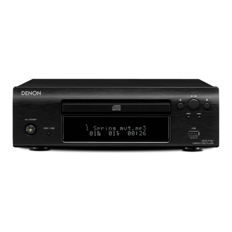
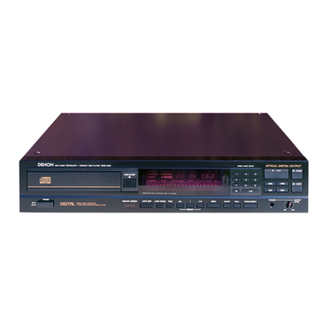
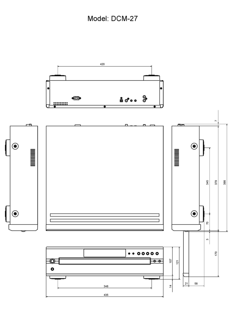
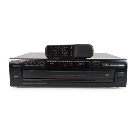
Denon DCD-1500II User manual

DENON
_........
SERVICE
MANUAL
STEREO
CD
PLAYER
MODEL
DCD-
15001
NIPPON
COLUMBIA
Co.
LTD.

TABLE
OF
CONTENTS
;
Baa
=r"
i
PE
RI
Shs
oe
ers
ehond
Solent
ew
as
ge
crs
tliat
lane
3
dd
Dat
RE
et
2
H
SPECIFICATIONS
............--
rer
ee
ee
ee
eH
OE
ht
we
ead
3
i
NAMES
AND
FUNCTIONS
OF
PARTS
.........
000000
cece
ete
cee
ete
teen
eee
4,5
NOTE
FOR
HANDLING
OF
LASER
PICK-UP.......
eee
ud
caine
en
tanta
Sind
eats
ae
wise
6,7
DISASSEMBLY
.........
hang
edt
anseaitnta
dh
tptaatt
dh
teed
cd
Ses
cee
Raa
area
one
ge
Cad
tet
8~10
MAINTENANCE
SERVICE
AND
ADJUSTMENT.
............
00
ce
eee
eee
eee
11~17
PARIS
LIST.
OF
PW:
BOARD
occc
>
bce eee
Odie
hile
epee
wate
e
en
hee
18~
21
EXPLODED
VIEW
OF
FG-610
MECHA
UNIT...
00.2...
c
eect
eee
ee
nee
22
PARTS
LIST
OF
FG-610
MECHANISM
UNIT...
00.0.0.
0c
cece
eee
tee
eee
tenes
23
PARTS
LIST
OF
EXPLODED
VIEW
¢.5
oo
Nev
eoenos
sea
esGab
a
duces
oda
sie
es
24
EXPLODED
VIEW
x
ac
cance
pice
ea
ea
EO
Bren
wet
we
RS
<
25
PW:
BOARD
oid
case
Poke
ad
pals
Bo
GRO
eo
ae
ae
ae
TE
ae
26,
27
WIRING
DIAGRAM
efi
ached
ot
teers
se
eG
dale
nen
ae
eats
aed
aoe
atan
PEs
28
SCHEMATIC
DIAGRAM:
ior5.o
keen
Ko
NtL
bon
eae
wa
edane
ane
he
haere
29
SEMICONDUCTORS
sues
ne
dese
eee
foie
ese
ee
a
ewe
e
aan
ewe
eee
eas
30
i
)
j
i
ar
|
i
i
:
I
t
fi
i
'
1
1
|
|
\
{
H
FEATURES
The
DCD-1500I
compact
laser
disc
player
utilizes
a
unique
DENON
Super
Linear
Converter
which
prevents
deterioration
of
sound
quality
in
the
PCM
playback
system,
assuring
accurate
reproduction
of
sound
record
on
compact
laser
discs,
in
the
studio
or
in
live
sound
production
areas.
The
parts
for
this
high
performance
.
disc
player
have
been
selected
with
careful
discrimination,
to
produce
high
quality,
realistic
playback
of
the
full
musical
production.

SPECIFICATIONS
AUDIO
No.
of
channels:
Frequency
response:
Dynamic
range:
Signal-to-noise
ratio:
Harmonic
distortion:
Separation:
Wow
and
flutter:
Output
voltage:
DISCS
GENERAL
CHARACTERISTICS
Power
supply:
Power
consumption:
Dimensions:
Weight:
FUNCTIONS
AND
DISPLAY
Functions:
Display:
Other
functions:
REMOTE
CONTROL
UNIT
Remote
control
system:
Power
supply:
External
dimensions:
Weight:
ACCESSOIRES
ee
=
2
channels
2
~
20,000
Hz
96
dB
103
dB
0.003%
(1
kHz)
100
dB
(1
kHz)
Less
than
the
measuring
limit
(+0.001%
W.
peak)
Fixed:
2.0V
Variable:
Max.
2.0V
Audio
compact
discs
are
used.
50/60
Hz,
Voltage
is
shown;
on
rating
label
17W
434
(17.1
in)
X
x
107
(4.2
in)
H
x
324
(12.8
in)
D
mm
e
9.3
kg
Direct
selection,
automatic
search,
programmed
selection,
repeat
playback,
manual
search,
auto
space,
time
mode,
call,
auto
edit.
Track
number,
index
number,
time,
program,
and
direct,
etc.
Headphone
Jack
(Variable
level)
Digital
out
ON/OFF
Switch.
RC-202
—
Infrared
pulse
system
’
3V
DC
Two
SUM-3
(standard
size
AA)
dry
cell
batteries
62
(2.4
in)
W
x
162
(6.4
in)
H
x
18
(0.7
in)
D
mm
120
g
(Includes
batteries)
Connecting
pin
cord,
Mini
screwdriver
*
Design
and
specifications
are
subject
to
change
without
notice
in
the
course
of
product
improvement.
VAROITUS:
SUOJAKOTELOA
El
SAA
AVATA.
LAITE
SISALTAA
LASER-DIODIN,
JOKA
LAHETTAA
NAKYMATONTA
SILMALLE
VAARALLISTA
LASER-SATEILYA.
ADVARSEL:
USYNLIG
LASERSTRALING
VED
ABNING
NAR
SIKKERHEDSAFBRYDERE
EU
UDE
AF
FUNKTION.
UNDGA
UDSAETTELSE
FOR
STRALING.
“CLASS
|!
LASER
PRODUCT”
“CLASS
1
LASER
PRODUCT”

CAUTION
SE
WF
CET
See
sens
orn
@
Power
Switch
(POWER)
e
Press
this
switch
to
turn
the
power
source
ON.
-
e@
After
the
power
is
turned
on,
the
Variable
Output
level
is
displayed
in
the
S
(sec)
portion
of
the
display
window,
then
the
Track
No.
(QQ)
lights
up.
If
no
disc
is
loaded,
all
number
indicators
and
the
calendar
light
up
after
several
seconds.
If
a
disc
has
been
loaded,
the
number
of
tracks
on
the
disc
wil!
be
displayed
in
the
Track
No.
display
after
a
few
seconds,
and
the
total
time
will
be
displayed
by
the
Time
display.
The
Calendar
display
wiil
stay
on
until
the
total
number
of
tracks
is
displayed,
(but
will
indicate
OVER]if
there
are
more
than
21
tracks
on
the
disc).
It
will
go
off
when
playing
starts.
2)
Diet
Holder
The
disc
is
loaded
into
the
disc
holder
for
play.
e
The
disc
holder
is
opened
and
closed
by
pressing
the
disc
holder
open/close
button
(
4
OPEN/CLOSE)
@.
®
It
can
also
be
closed
by
pressing
the
play
button
(
P~
PLAY)
@®
or
pause
button
(
Il
PAUSE)
@®.
@
Disc
Holder
Open/Close
Button
(
4
OPEN/CLOSE)
e@
The
disc
holder
C2]
is
opened
and
closed
by
pressing
this
button.
@
Press
the
button
once
to
eject
the
disc
holder
(2)
forward.
Press
it
again
to
close
the
holder.
@
If
the
disc
holder
is
closed
and
a
disc
has
been
loaded,
the
disc
is
rotated
for
several
seconds,
and
then
the
total
num-
ber
of
tracks
on
the
disc
and
the
total
playback
time
are
then
displayed
on
the
digital
display
@.
4)
Display
e@
The
display
area
consists
of
sections
for
the
track
number,
the
index,
the
playback
time,
and
the
calendar.
Direct
Remote
control
indicator
sensor
indicator
Emphasis
indicator
Pause
indicator
Playback
Remainder
of
indicator
Current
track
indicator
@REMOTE
SEARCH
EMPHASIS
@§
[PAUSE]
DIRECT
»(CPLAY7
u
a
INDEX
aa
ann
Geo
okt
Program
Total
remaining
indicator
indicator
\
time
indicator
Calendar
Recorded
track
overflow
Autospace
Repeat
between
indicator
(for
discs
with
indicator
A
and
B
indicator
21
or
more
track
numbers}
Remote
Control
Photosensitive
Window
This
window
receives
the
light
transmitted
from
the
wire-
less
remote
control
unit.
The
RC-202
wireless
remote
control
unit
should
be
operat-
ed
while
it
is
pointed
in
the
direction
of
the
photosensitive
window.
When
the
remote
control
is
operated,
the
remote
control
sensor
indicator
lamp
will
light
in
the
display
area
Auto
Edit
Button
(AUTO
EDIT)
This
automatic
programming
function
devided
the
compatt™
disc,
which
is
recorded
on
only
one
side,
into
two
halves,
to
resemble
side
A
and
B
of
an
ordinary
analog
disc.
Total
playing
time
is
divided
at
the
break
between
tracks
which
is
nearest
to
the
1/2
point.
The
break
is
made
at
the
beginning
of
the
track
to
avoid
interrupting
the
trackduring
playback.
Pressing
this
button
when
the
player
is
stopped
causes
the
playback
time
for
the
first
half
of
the
disc
to
be
displayed
for
approximately
2
seconds
in
the
TIME
display,
along
with
the
numbers
of
the
tracks
on
that
side,
displayed
in
the
CALENDAR
display.
Next,
the
content
of
the
second
half
of
the
disc
is
displayed
in
the
same
way.
The
player
then
moves
automatically
to
the
start
of
the
initial
track
and
remains
there
in
the
pause
state.
Play
is
started
by
pressing
either
the
Play
(PLAY)
or
the
Pause
(PAUSE)
button.
When
playing
of
the
first
half
of
the
disc
is
ended,
the
player
pauses
automatically
at
the
start
of
the
first
track
of
the
second
half.
This
function
operates
only
when
a
disc
with
20
or
fewer
tracks
is
played.
AuTe
SPACE
Button
(AUTO
SPACE)
Pressing
this
button
will
cause
the
[AUTO
SPACE]
indicator
to
light
up
and
a
blank
portion
tasting
4
or
more
seconds
to
be
inserted
between
the
tracks.
If
this
button
is
pressed
while
the
[AUTO
SPACE]
indicator
is
lit,
the
lamp
will
go
off
and
the
auto
space
function
will
be
cancelled.
When
the
AUTOMATIC
SEARCH
button
(Kd,
PPI)
is
pressed,
the
auto
space
function
will
not
operate.
The
auto
space
function
will
operate
with
Programmed
playback
as
wel!
as
normal
playback.
Although
a
blank
interval
is
inserted
between
tracks
when
the
Auto
Space
function
is
operating,
the
4-second
interval
is
not
added
to
the
time
remaining
display
or
to
the
time
display
during
Auto
Edit.
Time
Mode
Button
(TIME)
This
button
is
used
to
select
the
type
of
information
to
be
read
out
under
the
TIME
section
of
the
display.
Either
the
elapsed
playback
time
of
the
current
track,
the
remaining
playback
time
for
that
track,
or
the
playback
time
for
the

remaining
tracks
on
the
disc
can
be
selected.
Normaily
the
elapsed
playback
time
of
the
current
track
is
displayed.
If
the
button
is
pressed
once,
the
in-
dicator
lights
and
the
remaining
time
left
to
play
on
the
track
is
displayed.
If
the
button
is
pressed
again,
the
SINGLE
|
indicator
goes
out,
and
the
[TOTAL
|
indicator
goes
on,
and
the
playback
time
for
the
remaining
tracks
left
on
the
disc
is
displayed.
If
the
button
is
pressed
once
more,
the
TOTAL
|
indicator
goes
out
and
the
display
returns
to
the
elapsed
playback
time
for
that
track.
If
the
button
is
pressed
so
that
the
LTOTAL
Jindicator
lights
during
programmed
playback,
the
playback
time
for
all
of
the
remaining
programmed
tracks
is
displayed.
All
Button
(ALL)
e@
Press
this
button
to
repeat
playback.
@
When
the
[ALL]
button
is
pressed,
the
[REPEAT
]
indicator
lights
and
repeated
playback
is
performed
for
all
of
the
tracks
on
the
disc.
During
programmed
playback,
all
of
the
tracks
programmed
into
memory
are
played
repeatedly.
Press
the
[REPEAT
|
button
again
to
cancel
the
repeat
operation.
One
Track
Repeat
Button
(1)
@
Press
this
button
when
desiring
to
replay
1
track
only.
Pressing
this
button
while
a
track
is
playing
will
cause
the
player
to
replay
that
track
only.
(Refer
to
page
8).
A-B
Repeat
Button
(A
—
B)
@
Press
this
button
to
perform
repeated
playback
of
a
desired
section
between
two
specified
points.
(Refer
to
page
8
for
details.)
Index
Button
(INDEX)
e@
Press
this
button
when
playing
from
the
index
within
the
tracks.
Specify
the
index
No.
from
the
ten
key
pad.
Clear
Button
(CLEAR)
e
Use
this
key
to
make
corrections
in
the
programmed
tracks.
Call
Button
(CALL)
@
Press
this
button
to
verify
the
track
numbers
that
have
been
programmed
into
memory.
Program
and
Direct
Button
(PROG/DIRECT)
@
Press
this
button
to
select
the
memory
program
function
or
direct
track
selection
function.
+10
Button
(+10)
@
Press
this
button
to
select
a
track
number
that
is
larger
than
11.
e@
The +10
button
is
used
in
conjunction
with
the
ten-key
pad
@.
For
example,
to
select
track
number
15,
press
the
button
and
then{S]on
the
ten-key
pad.
@
Similarly,
to
select
track
number
32,
press
[+10]
,
[+10],
+10]
and
then
press
[2].
Ten
key
red
(1,
2,
3, 4, 5, 6,
7,
8,
9,
10)
These
buttons
are
pressed
for
direct
track
selection
or
to
Program
a
selection
into
memory.
For
example,
to
play
back
the
third
track
using
the
direct
selection
function,
press
[3]
on
the
key
pad.
Track
number
3
will
then
start
to
play.
To
play
track
number
12,
press
[+10]
and
then
:
@
To
use
the
keypad
in
program
mode,
first
press
the
(PROG/
DIRECT)
button
@®
to
enter
the
correct
mode.
Play
Button
(
»
PLAY)
e
Press
this
button
to
play
a
disc.
@
When
the
PLAY
button
is
pressed,
the
[PLAY]
indicator
lights,
and
the
number
of
the
track
being
played,
the
index
number,
and
the
elapsed
playback
time
for
that
track
are
displayed.
The
calendar
lights
to
display
the
all
of
the
playback
tracks.
The
displayed
tracks
then
go
out
in
order
as
each
finishes
playing.
@
When
playback
of
the
last
track
has
finished,
the
indicator
goes
out,
and
the
machine
enters
stop
state.
@
It
is
also
possible
to
use
the
PLAY
button
to
close
the
disc
holder
after
a
disc
has
been
inserted.
Playback
then
begins.
@®
pene
Button
(
Il
PAUSE)
Press
this
button
to
stop
the
playback
temporarily.
e
If
the
PAUSE
button
is
pressed
during
playback,
the
play
is
stopped
temporarily,
the
[PBPLAY]
indicator
goes
out,
and
the
[LILPAUSE
indicatortinhdiae-
-
e
To
end
the
pause,
push
the
PLAY
button
@®
or
PAUSE
button
®
again.
@®
Stop
Button
(HM
STOP)
@
Press
this
button
to
stop
the
playback.
@
The
rotation
of
the
disc
stops,
and
the
total
number
of
tracks
and
the
total
playback
time
are
read
out
on
the
TRACK
NO,
and
TIME
sections
of
the
display.
@
During
programmed
playback,
the
total
number
of
tracks
programmed
in
memory
and
the
total
programmed
per-
formance
time
are
displayed.
@
Automatic
Search
Reverse
Button
(
Kd
)
@
Press
this
button
to
move
the
pickup
backward,
to
return
to
the
beginning
of
the
desired
track.
e
If
this
button
is
pressed
during
playback
or
pause,
the
pick-
up
moves
back
ward
to
the
beginning
of
the
track
that
corresponds
to
the
number
of
times
the
button
was
pressed.
@
Automatic
Search
Forward
Button
(
>>I
)
@
Press
this
button
to
move
the
pickup
forward
and
advance
to
the
beginning
of
the
desired
track.
e
If
this
button
is
pressed
during
playback
or
pause,
the
Pick-
up
moves
forward
to
the
beginning
of
the
track
that
corres:
ponds
to
the
number
of
times
the
button
was
pressed.
@
Manual
Search
Reverse
Button
(
<4
)
©
Press
this
button
to
move
playback
in
fast
reverse.
@
When
the
machine
is
in
play,
sound
will
be
produced
during
the
time
that
the
button
is
being
pressed
and
the
fast
re-
verse
is
operating.
e
If
the
button
is
pressed
while-the
machine
is
in
the
Pause
state,
the
fast
reverse
will
operate
three
times
faster
than
the
reverse
speed
when
the
machine
is
in
the
play
state.
~
No
sound
will
be
produced.
@)
Manual
Search
Forward
Button
(
>>
)
@
Press
this
button
to
move
playback
in
fast
forward.
@
Whe
the
machine
is
in
play,
sound
will
be
produced
during
the
time
that
the
button
is
being
pressed
and
the
fast
for-
ward
is
operating.
e
lf
the
button
is
pressed
while
the
machine
is
in
the
Pause
state,
the
fast
forward
will
operate
three
times
faster
than
the
fast
forward
speed
when
the
machine
is
in
the
play
state.
No
sound
will
be
produced.
@
Headphone
Jack
(PHONES)
@
When
using
headphones,
please
listen
to
them
at
an
appro-
priate
volume.
(Headphones
are
sold
separately.)
@®
Volume
adjustment
knob
e@
This
knob
is
used
to
adjust
the
output
level
(volume)
of
the
headphone
jack.
@
Digital
Output
Switch
(DIGITAL
OUTPUT)
©
Use
this
switch
to
turn
the
digital
output
terminal
signal
on
and
off.
©
The
digital
signal
is
not
output
when
this
switch
is
off.
@)
Output
terminal
(FIX-VARIABLE)
@
Connect
the
output
terminal
to
the
input
terminal
of
the
amp.
(Refer
to
page
6
for
details
on
connections.)
@®
Digital
Output
Terminal
(DIGITAL
OUTPUT-
COAXIAL)
@
This
terminal
outputs
digital
data.
@
Digital
Output
Terminal
(DIGITAL
OUTPUT-
OPTICAL)
This
terminal
output
data
as
fight.
Optical
fiber
cord
used:
Tos-Link
types
TOCP155
or
TOCP172.
Z
Caution:
Optical
fiber
cord
is
sold
separately.

NOTE
FOR
HANDLING
OF
LASER
PICK-UP
@
NAMES
OF
PARTS
e
NAME
PLATE
==:
.
oe
+Z-axis
Direction
—_
Z-axis
Cover
KSS-I5IA
Object
Lens
;
OOOO0O0
Slide
Base
©
C00:
Year
(last
figure)
Day
Month
Quality
Control
No.
LotNo.
CO
O
OO
O
OP
Unit
:
Note:
Month
indication
X,
Y,
Z
signify
10,
11,12.
lo
Nameplate
Z-axis
P
O
O
O
O
Y-axis
Controf
Letter
|
1
Figure
1st
Decimal
Place
¢
by
the
Plant
(Tangentia}
Direction)
10
Figures
X-axis
(Radial
Direction)
Indication
unit
is
mA
omitted
a
decimal
point.
@
CONNECTION
DIAGRAM
OF
CONECTOR
(1)
KSS
151A
Accessory
flexible
wire
terminals.
:
Soldered
Short
Circuit
Portion
(A)
A
a
@
CONNECTION
DIAGRAM
OF
CONECTOR
(2)
KSS-151A
>
TERMINAL
P.W.B
>
MAIN
P.W.B
2U-1461
TERMINAL
PW.B
2U-1454
MAIN
PW.B
I
Soldered
Short
Circuit
Portion
(A)
\}
Note:
The
soldered
connecting
portion
must
be
bridged
“So
when
removing
CC102.

eee
eee
ea
Cautions
for
Handling
the
Laser
Pick-up
The
laser
pick-up
KSS-151A
is
assembled
and
precisely
adjusted
using
a
sophisticated
manufacturing
process
in
our
plant.
Do
not
disassemble
or
attempt
to
readjust
it.
Please
keep
the
following
instructions
carefully
in
handling
pick-
up.
1.
General
Care
(1)
Storage
Do
not
store
the
pick-up
in
dusty,
high-temperatured
or
high-humidity
environments.
(2)
Please
take
care
for
preventing
from
shock
by
falling
down
or
careless
handling.
2.
Laser
Diode
(LD)
(1)
Protect
your
eyes
The
laser
beam
may
damage
the
human
eye,
since
the
intensity
of
the
focused
spot
may
reach
1.3
x
10*
W/
cm?
even
if
the
intensity
at
the
object
lens
is
400
UW
maximum,
As
the
light
beam
spreads
after
focused
through
the
objective
lens,
it
does
not
effect
you
in
the
place
as
far
as
more
than
30cms.
However,
do
not
look
at
the
laser
light
beam
either
through
the
objective
lens
directly
nor
another
lens
or
a
mirror,
(2)
Poison
of
As
Since
the
LD
chip
contains
As
(Arsenic),
as
GaAs
+
GaAlAs,
as
known
as
the
poison,
although
the
poison
is
relatively
weak,
in
comparing.
with
others,
e.g.
As,03,
AsCl3
etc.,
and
the
amount
is
small,
avoid
putting
the
chip
in
acid
or
an
alkali
solution,
heating
it
over
200°C
or
putting
it
into
your
mouth...
..
(3)
Avoid
surge
current
or
electrostatic
discharge
The
LD
may
be
damaged
or
deteriorated
by
it’s
own
strong
light
if
a
large
current
is
supplied
to
it,
even
if
only
a
short
pulse.
—
-Make
sure
that
there
is
no
surge
current
in
the
LD
driving
circuit
by
switches
or
else.
Be
careful
to
handle
pick-up
as
it
may
be
damaged
in
a
moment
by
human
electrostaic
discharge.
The
pins
of
the
LD
are
short-
circuited
by
solder
for
protection
during
shipment
(Soldered
short
circuit
portion
(A)].
For
safety
handling
of
an
LD,
grounding
the
human
body,
measuring
equipments
and
jig
is
strongly
recom-
mended,
And
still
it is
further
desirable
to
make
use
of
mat
on
the
platform
and
floor
for
handling
the
LD.
To
open
the
short
circuit,
remove
the
soldering
quickly
with
a
soldering
iron
whose
metal
part
is
grounded.
The
temperature
of
the
soldering
iron
should
be
less
than
320°C
(30W).
'\
3,
X-axis
Actuator
(1)
The
performance
of
the
actuator
may
be
effected
if
magnetic
material
is
located
nearby,
since
the
actuator
has
a
strong
magnetic
circuit.
Do
not
permit
dust
to
enter
through
the
clearance
of
the
cover.
(2)
Cleaning
the
lens
It
may
change
the
specifications
when
dust
or
dirt
is
stuck
on
the
object
lens.
For
cleaning,
use
a
dry_tense¥@aning
paper
applying
no
excessive
pressure
to
the
lens.
If
it is
difficult
to
re-
move
it,
moisten
the
paper
with
a
little
amount
of
water.
At
this
time
never
drip
water
other
than
the
lens
portion.
4.
The
Metal
Bearing
The
metal
bearing
of
Cu-compound
sintered
alloy
is
im-
pregnated
with
oil.
However,
supply
oi!
with
the
specified
oil
Froil
0147P,
at
the
pick-up
replacing
time.
You
do
not
normally
need
lublicate
the
bushing
in
initializing
time
nor
supplying
oil
in
running
time.
5.
Handling
Please
handle
the
laser
pick-up
with
holding
by
optical
base.
When
either
a
part
of
human
body
or
some
other
things
may
happen
to
touch
directly
with
the
circuit
part
of
either
the
LD
or
PD
PCB,
it
may
cause
deterioration,
take
careful
attention
in
handling
this
base.
6.
Deterioration
of
Laser
Pick-up
When
difficulty
occurs
either
in
focus
or
tracking
adjust-
ment
nor
able
to
adjust
the
focus
or
tracking,
it
seems
that
the
laser
pick-up
is
deteriorated.
In
these
cases,
check
a
value
of
laser
diode
current
and
give
a
decision
for
deterioration.
7.
Fundamental
Deterioration
Decision
of
Laser
Pick-up
(1)
If
a
voltage
value
across
Pin
@)
of
TP102
(+5V)
and
Pin
@
(iop)
of
Unit
(2U-1454)
is
V1,
the
value
of
laser
diode
current
“‘iop
1’’
can
be
found
a
formula
iop
it
(2)
If
a
“iop”
exceeds
+10%
compared
with
the
IOP
indi-
cation
on
the
laser
pick-up
mameplate,
there
is
a
fair
chance
for
deterioration
when
it
is
checked
under
a
circumambient
temperature
23°C.
(3)
When
the
circumambient
temperature
changes
+10°C,
“iop
1”
will
change
5%.
The
“‘iop
1°’
will
also
be
changed
the
passage
of
time.
(4)
In
case
of
the
above
conditions
taking
into
considera-
tion
and
performed
the
adjustment
in
proper
way,
if
the
HF
level
across
pin
(1)
and
across
(HF)
GND
of
TP102
in
2U-1454
becomes
0.6V
or
less
values;
or
a
_
gitter
occurs
great,
the
laser
pick-up
is
may
be
deteriorated.

DISASSEMBLY
Top
Cove
4
anne
oe
e
Top
Cover
me
D
h
Slanty
U
d
1.
Remove
4
screws
on
upper
side
of
the
Top
Cover.
ae
ica
2.
Pull
the
Top
Cover
slantwise
upward
with
opening
the
bottom
parts
slithgly
right
and
left.
pen
the
lower
part
right
and
left.
(Caution
in
assembling
Top
Cover)
1.
Couple
the
hook
in
the
center
position
of
the
Top
Cover
with
the
notch
part
of
Front
Panel.
Top
Cover
{
1
{
i
Front
Panel
i
i
1
|
i
i
i
1
i
t
i
H
i
5
|
|
|
|
2.
Make
the
setting
as
no
clearance
between
Front
Panel
and
the
Top
Cover
viewing
from
the
upper
side
of
the
setting.
Top
Cover
|
A
Front
Panel

e
Bottom
Cover
1.
Remove
9
screws
holding
the
Bottom
Cover
and
detach
;
Bottom
Cover
the
Bottom
Cover
with
the
Insulaters
attached.
(Doubled)
Bottom
Cover
Holding
4
Screw
3
x
10
1
|
NF
laguietor
e
Insulator
and
seperating
the
Double
Bottom
Cover
Detach
the
Bottom
Cover,
and
remove
8
screws
securing
the
Insulators
to
take
out
Insulators
and
separate
Doubled
Bottom
Cover,
Note:
The
hook
may
break
if
it
is
pushed
top
firmly.
A
square
hole
on
the
front
panel
as
a
stopper
to
:
insert
a
G)
screwdriver
(approx.
@6)
not
coming
into
top
far.
Insulator
securing
screw
Bottom
Cover
(Doubled)
<a
Insulator
e
Front
Panel
1.
Remove
the
Top
Cover,
and
unfasten
3
screw
(A)on
the
upper
side.
®
¥
2.
Push
and
release
3
each
hooke
on
the
upper
and
lower
af
sides.
Then
draw
out
the
Front
Panel
frontward
and
de-
Front
Panel
tach
it.
Hook

10
FG-610
LASER
PICK-UP
MECHANISM
How
to
move
the
Looder
Frame
manually
Manually
push
the
lock
arm
(a)
to
the
rightward
and
pull
the
Loader
frontward,
then
the
Loader
can
be
open/close
manually.
Whole
body
of
the
Laser
Pick-up
Mechanism
FG-610
Removing
4
screw
makes
possible
to
detach
whole
body
of
the
Laser
Pick-up
Mechanism
from
the
Chassis.
Loader
Frame
Remove
whole
body
of
the
Laser
Pick-up
Mechanism
FG-610,
pull
the
Loader
Frame
frontward,
lift
the
Loader
Rail
G4)
upward
and
pull
it
out
backward,
then
the
Loader
Frame
can
be
taken
out.
Housing
Assembly
Remove
4
screw
Or
=
(a)3,
and
detach
the
Assembly
composed
of
Laser
Pick-up
Magnet,
Yoke,
Turntable,
and
Spindle
Motor.
By
removing
of
screw
@).
the
parts
for
mechanism
floating
can
be
taken
down
as
illustration
shows.
When
reassembling,
remind
that
the
Washer
and
H-damper
are
commonly
used,
but
the
Coil
Spring
and
Collar
are
provided
two
types
for
maintaining
equilb-
rium.
4630515
000
COIL
SPRING
(D)
463
0515
000
433
0484
004
COLLAR
(A)
433
0485
003
COLLAR
(B)
COIL
SPRING
(D)
433
0485
003
COLLAR
(B)
.463
0514
001
COIL
SPRING
(C)
Coil
spring
(D)
(used
3
each)
is
marked
in
red.
Coil
spring
(C)
(used
3
each)
is
not
marked.
Collar
(B)
(used
2
each)
is
made
of
brass
(yellow).
Collar
(A)
(used
2
each)
is
made
of
brass
plated
with
nickel
(white)
Laser
Pick-up
KSS-151A
(1)
Detach
the
Housing
Assembly
illustration.
(2)
Remove
2
screws
@),
unsolder
2
portions
(8),
and
detach
the
Speed
Detection
Coil.
(3)
Next,
remove
2
screws
)
unsolder
2
portions
(),
and
detach
the
Drive
Coil.
And
pull
out
the
Shaft
at
portion
(E
),
then
the
Lase
Pick-up
can
be
taken
out.
Washer
Coil
Spring
(C),
(D)
H-damper
Collar
(A),
(B)
om,

“|
1
i
i
1
}
H
Hl
MAINTENANCE
SERVICE
AND
ADJUSTMENT
Changing
and/or
repairing
component
parts
may
necessitate
readjustment.
The
microcomputer
employed
in
this
unit
‘contains
maintenance
service
program.
All
necessary
ad-
justment
can
be
made
via
operation
buttons
in
front
nor-
mally
used
to
play
the
unit.
1.
Initializing
maintenance
service
program.
(1)
Turn
power
OFF.
(2)
Short-circuit
pins
(3)
and
(4)
of
TP102
in
the
signal
processing
PCB
(2U-1454).
:
(3)
Turn
power
ON,
The
service
program
initializes
and
Bi
/
displays
on
the
track
number
indicator.
2
figures
—
also
displays
on
the
time
indicator’s
second
part
has
no
relation
with
the
service
program.
Note)
When
the
service
program
is
initialized,
the
unit
comes
into
service
use
only
and
does
not
accept
normal!
operation.
2.
Button
operations
during
the
service
mode.
(1)
4
OPEN/CLOSE
Button
Opens
or
Closes
the
disc
holder
in
the
state
of
disc
rotation
being
stopped.
Note
that
when
the
holder
is
in
operation,
all
other
buttons
are
inoperative,
until
the
holder
operation
completed.
Note)
Be
sure
to
remove
the
short
circuit
or
reconnect
the
connector
which
disconnected
to
initialize
the
service
program.
Otherwise
the
Open/Close
does
not
function
correctly.
(2)
=
STOP
Button
Stops
the
system.
Track
number
indicator
displays
{7
|.
Push
the
button
when.
the
servo
adjustment
completed,
or
when
redo
it.
(3)
»
PLAY
Button
Turns
focus
servo
on
and
starts
the
disc.
When
a
sequential
functions
ends,
the
track
number
indicator
display
{j—'
.
Use
it
to
adjust
tracking
offset.
(4)
IEPAUSE
Button
=
Turns
all
functions
of
focus
servo,
tracking
servo,
slide
servo
and
spindle
servo
on.
When
a
sequential
func-
tions
ends,
the
track
number
indicator
displays
an
When
the
PLAY
has
already
been
pushed,
turns
both
tracking
servo
and
slide
servo
on.
(5)
Other
buttons
Other
buttons
previously
not
mentioned
are
for
factory
use.
Some
of
the
buttons
have
specific
func-
tions
like
checking
IC.
Operation
of
these
buttons
could
invite
incorrect
CD
player
operation.
Therefore
never
operate
buttons
which
are
not
previously
ex-
plained
how
to
use.
If
these
buttons
are
accidentally
pushed,
turn
power
off
immediately
and
initialize
the
service
program
again.
Also
never
use
remote
control-
ler
when
the
service
program
is
in
operation.
3.
Adjustment
(1)
Precaution
to
the
Adjustment:
The
super
linear
convertor
employed
in
this
unit
re-
quires
no
adjustment,
except
a
specific
case.
(2)
Equipment
required
1
Dual
mode
oscilloscope
2
Specific
disk
for
adjustment
3
Audio
oscillater
10
Hz
~
10
kHz,
Output:
0
V
~
3
Vp-p
4
Frequency
counter
Readable
to
over
5
MHz
5
Filter
(Network)
for
measurement
33k
i
jaa
OUT
11

12
(3)
Setup
LF401
FAN
VRIO3
:
BW
&
PLL.
[e)
Iclo2
TPIOS
VRIO6
SLIDE
OS.
2U-1454
Front
Panel
Side
Confirm
the
power
is
OFF,
short-circuit
pins
VRIOI
:
+
©
and
(@)
of
TP102.
Then
turn
ON
the
power,
=
io
Unies
initialize
the
service
program.
Confirm
the
track
VRIO4
adiotcack
number
indicator
displays
/,
/
,
then
revert
the
einer
connection
of
connector.
VRIOS
Preset
VR101
~
106
as
per
following.
®]
4
o'clock
3)
7
o'clock
Make
adjustment
in
the
order
of
VRIO2
1,
PLL
5
Focus
offset
2.
Slide
offset
6
Tracking
gain
3
Track
offset
7
Tracking
offset
(Recheck)
VRIO6
aN
4
Focus
gain
12
o’clock
(4)
PLL
‘)
Precaution
®@
Confirm
the
service
program
is
initialized,
and
the
disc
is
not
loaded
or
the
disc
is
stopped.
Front
Panel
Side
@
Ground
the
test
points
TP104
(ASY)
and
10:1
Probe
TP105
(BW).
Equipment
setup
Connect
test
point
TP202
(PLCK)
terminal
to
the
PLCK
terminal
(4)
frequency
counter
+
side
via
a
10:1
probe
used
for
GND
i
(-)
oscilloscope
and
ground
—
side
to
the
GND.
GB)
Adjustment
Frequency
Counter
Adjust
VR105
with
a
screwdriver
so
that
the
frequency
counter
reads
3.50
MHz.
+
10
kHz.
@)
After
the
Adjustment
@
Remove
ground
from
test
points
TP104
(ASY)
and
TP105
(BW).
@
Disconnect
frequency
counter.

(5)
Stide
offset
Confirm
the
STOP
mode
(indicating
[/
/).
a2
Connection
of
measuring
equipment.
4
Connect
test
point
(SLIDE
OFFSET)
located
the
_-
—==smyscilloscope
side
of
VR106
to
the
oscilloscope
+
side,
and
ground
-
side
to
the
GND.
Ground
the
input
terminal
of
oscilloscope
to
con-
firm
the
base
tine.
Then
select
oscilloscope
input
mode
at
DC
range,
sweep
time
as
1ms
~
2ms/div,
SLIDE
OFFSET
Q——————_———_0
+
sensitivity
as
high
(0.02
V
~
0.05
V/div
when
10:1
terminal
|
probe
is
used)
to
make
judging
0.1
V.
GND
O———_———__,°
—
GB)
Adjustment
Adjust
VR106
so
that
the
waveform
becomes
OV
+
0.1
V
on
the
oscilloscope.
(6)
Tracking
offset
Equipment
setup
'
Filter
Oscilloscope
f~
eae
Fae
ay
'
|
|
Pin
(3)
of
TP101
a
TEO*
|
|
|
0.001
|
J
!
|
i
(+)
Pin(S)
of
TP101
(-)
:
GND
I
i
|
PA
te
es
4
*TEO
:
Tracking
Error
Out
|
|
;
{
|
st
|
i
i
(2)
Push
4
OPEN/CLOSE
button
to
open
the
holder,
put
the
disc
for
adjustment
on
the
tray,
and
push
the
button
again
to
close
the
holder.
When
the
service
program
is
initialized,
the
laser
P.U.
is
set
to
the
optimum
position.
A
a
(3)
Push
P
PLAY
button
to
start
the
disc,
(4)
Ground
the
oscilloscope
input
terminal
to
confirm
;
the
base
line,
and
set
the
oscilloscope
input
to
DC
range,
0.1
V/div
(when
10:1
probe
is
used),
and
sweeping
time
as
1
ms
~
2
ms/div.
(©)
Adjust
VR101
so
that
the
amplitude
of
A
equals
B
as
per
figure
on
the
right.
Base
Line

(7)
Focus
gain
Push
Il
PAUSE
bution.
Equipment
setup
a
Filter
Oscilloscope
Pin)
of
TP-101
FEO
x
Pin
Q)
of
TP-101
©
FEL
Pin
©
of
TP-101
0
*FEO:
Focus
Error
Out
FE!:
Focus
Error
In
Frequency
Counter
3)
Adjustment
@
Set
the
audio
oscillator
output
to
620
Hz,
1.0
Vp-p
(+0.1
V).
@
Select
oscilloscope
input
in
X-Y
mode
so
to
observe
Lissajous
waveform
(Select
DC
range
for
both
X
and
Y
inputs).
@
Adjust
VR102
so
that
each
Lissajous
waveform
symmetrizes
X
and
Y
axes.
(Adjust
each
input
phase
90°)
Yaxis
Y
axis
X
axis
Correct
waveform
Incorrect
waveform
14
Oscillator
Set
to
620Hz,
1Vp-p
X
axis

(8)
Adjustment
of
Focus
Offset
Adjust
it
in
the
same
condition
as
to
focus
gain
in
the
state
of
all
the
servos
are
operated
by
pushing
PAUSE
Button
except
the
measuring
equip-
ment
connections,
°
@)
Connection
of
measuring
equipment
HF
Pin
Q)
of
TP-102
Test
point
E
Pin
(2)
of
TP-101
Pin
©
of
TP-101
=a
Oscilloscope
Audio
Oscillator
Set
to
620Hz,
1.0Vp-p
Frequency
Counter
3)
Adjustment
@
Set
the
output
of
audio
oscillator
to
620
Hz,
1.0
Vp-p(+0.1V).
@
Select
oscilloscope
input
mode
at
“ALTER-
NATE”
or
“CHOPPER”
and
set
it
to
50
mV/
div
or
20
mV/div
(use
10:1
probe).
Observe
by
setting
the
sweep
time
to
0.2
or
0.5
us/div
range.
IW
AWS
XY
va
Adjust
A
portion
for
most
fine
waveform.
@
A
waveform
to
observe
in
this
time
called
“Eye
Pattern’’.
@
Adjust
VR-103
for
a
minimum
jitter
amount.
15

(9)
Adjustment
of
Tracking
Gain
@
Adjust
it
in
the
same
condition
as
to
focus
gain
in
the
state
of
all
the
servos
are
operated
by
pushing
I]
PAUSE
Button
except
the
measuring
equip-
ment
connections.
Audio
oscillator
should
be
connected
while
the
servo
is
in
operation.
If
the
connection
is
made
before
servo
operation,
causing
mis-operation.
If
the
connection
is
made
in
failure,
disconnect
oscillator,
push
stop
button
(
=
STOP)
to
stop
all
operations,
and
follow
the
steps
from
the
begin-
ning.
Then
push
the
pause
button
(
j]|
PAUSE)
to
activate
the
servo
operation
again.
Connection
of
measuring
equipment.
Connect
all
kinds
of
measuring
equipment
setting
to
each
Test
Points
of
TP101
as
below
figures.
TEOX
Pin
@)
of
TP-101
TEL
Pin
©
of
TP-101
0
GND
Pin
©)
of
TP-1010
*
TEO:
Track
Error
Out
TEI:
Track
Error
In
@)
Adjustment
@
Set
the
output
of
audio
oscillator
to
2.1
kHz
3
Vp-p
+
0.1
V.
:
®
Select
oscilloscope
input
at
X-Y
mode
so
to
ob-
serve
Lissajous
waveform.
(Select
DC
range
both
X
and
Y
inputs.)
@
Adjust
VR-104
and
obtain
Lissajous
waveform
symmetric
to
both
X
and
Y
axes.
The
wave-
form
is
the
same
as
focus
gain
adjustment.
Frequency
Counter
=a
Oscilloscope
Audio
Oscillator
Set
to
2.1
kHz,
3Vp-p

(10)
Checking
of
Tracking
Offset
(Recheck)
@)
Check
the
adjustment
performed
in
the
previous
column
(6).
@
Push
stop
button
(
™
STOP)
to
stop
disc
re-
volution.
@
Push
play
button
(
»
PLAY)
and
check
that
the
disc
starts
to
run.
Note:
The
microcomputer
employed
in
the
unit
sometimes
does
not
accept
button
opera-
tion.
If
so,
push
the
button
again,
and
con-
firm
that
the
track
number
indicator
dis-
plays
“02”.
@
Observe
a
waveform
and
check
that
the
height
of
upper
and
lower
waveform
are
even
to
the
base
line.
(Reference
value:
Difference
of
height
between
two
is
5%
or
less.)
@
If
the
difference
is
beyond
the
value,
adjust
VR-101.
@)
That
is
all
to
complete
adjustments.
Terminal
@
Push
the
stop
button
(
™
STOP)
to
stop
disc
re-
volution,
and
push
open/close
button
revolu-
tion,
and
push
open/close
button
(4
OPEN
CLOSE)
to
open
the
holder
and
remove
the
ad-
justment
disc.
e
Remote
Control
IC
(LU59001)
Terminal
Function
List
Function
1
2
3
4
5
6
7
8
9
0
—=
Serial
Data
Output
+5
V
Shift
Clock
Input
RDY
Output
+5
V
455
kHz
OSC
455
kHz
OSC
-GND
Earth
ACL
Input
GND
Remote
Control
Code
Input
Input
Code
for
Remote
Control
out
of
RM577
System
Address
GND
Earth
System
Address
GND
Earth
System
Address
GND
Earth
System
Address
GND
Earth
System
Address
+5
V

PARTS
LIST
OF
P.W.
BOARD
2U-1454A
SERVO
&
SIG.
UNIT
Part
Name
Remarks
Remarks
2S8C1740(R/S)
RN1202
(10k-10k)
RN2202(10k-10k)
SEMICONDUCTOR
GROUP
CXA-1081S
(S-DIP)
CXA-1082AS
(S-DIP)
2730178022
2690025901
2690026900
TR116
TR201
TR202
2620842002
2620843001
2630257001
2630244001
2620522005
2620839002
-2620745002
2620635002
262051
7007
2630298002
2630423000
2620729002
2620593005
2620836005
2620419008
2630360008
2620419008
2620640000
2630257001
2630485006
2620844000
2630467008
2630190003
2630464001
2630272002
‘2630464001
263043
2004
2680063009
3939269003
2720025004
2740065044
2720058013
2740065044
2720058013
2740006002
2720025004
2730178022
2740065044
2720058013
2740006002
2720025004
2730178022
2690025901
18
M5218P
NJM082D
TC-4053BP
HD63A05Y0-C23P
HD74HC42
LU59001
MSL-917RS
LB1240
MS1953B
HD74HCO8P
HD74HCO4P
PCMS56P-J
HD14053BP
NE5532
HD14053BP
MN6632A
M5218P
NJM4556S
SM5807B
HA17812W
NJM79M12A
HA17805W
NJM79M0SA
HA17805W
NJM78LO5A
ICP-F20
PC-817
2SB562(C)
2SD880(Y)/{GR)
2S8834(Y)/(GR)
2SD880(Y)/(GR}
2SB834(Y)/(GR)
2SD468(C)
2SB562(C)
2SC1740(R/S)
2SD880(Y)/(GR)
2SB834(Y)/(GR)
2SD468(C)
2SB562(C)
28C1740(R/S)
RN1202(10k-10k)
TR401~
408
TR409
410
TR501
D101,102
D201
D202~
207
D208,405
p401~
404
D501,502
D503
D504
D505
D506
D507
2730253015
2690026900
2720025004
2760049008
2760049008
2760370007
2760049008
2760236031
2760405008
2760433902
2760224014
2760303003
2760049008
2760433902
RESISTOR
GROUP
|
2116064051
2116064006
2116064051
2116064064
2116064022
2110459002
2116064019
2452148000
2452153008
2SC2878(A/B)
RN2202
(10k-10k)
2SB562(C)
1S2076
1S2076
188106
182076
H2Z5C-1
S1WB(A)10
DSM1A2
HZ30-2
HZ6C-2
1$2076
DSM1A2
V06PB203
VO6PB103
VO6PB203
VO6PB102
VO6PB104
V1220025FA103
VO06PB473
RN14K2E360G
_
RN14K23560G
20k2B
10k2B
20k2B
1kQB
100kQ2B
10k2B
47k2B
362
%W
562
“AW
CAPACITOR
GROUP
2544260061
2551120055
2533617007
2544252037
2544260032
2561121025
2561034018
2551121025
2561034018
2539036006
2533603008
255H21041
CE04W1H3R3M
CQ93M1H272J
CC45SL1H390J
CEO04W1C101M
CEO4W1HR47M
CQ93M1H103J
CF93A1H333J
CQ93M1H103J
CF93A1H333J
CK45=1E104Z
CC45SL1H100D
CQ93M1H153J
3.3uF
50V
0.0027uF
50V
39pF
50V
100uF
16V
0.47uF
50V
0.01uF
50V
0.033uF
50V
0.01uF
50V
0.033uF
50V
0.14F
25V
10pF
50V
0.015uF
50V
@The
carbon
resistors
at
1/4W,
1/6W
are
not
listed
herein.

2561034047
2544260058
2539036006
C122
C123,124
C125~
127
C128
C129
C130,131
C132,133
C151
C154
C155
2551
120068
2533603008
2544260061
2544254019
2533636004
2551121025
2539036006
C156
2561034050
C157
2544254019
C158
2544254006
C159
Cci60
C162
C163
2561034018
2551121067
2533645008
2551
120068
C164
2551121025
C165,166|
2561035059
C167
2544260058
C168
2551120097
C171
2551120000
C172
2561034076
C173
2551121025
C174
2539036006
C175
2544254019
C176
2539036006
C177
2544260045
C178
2551120084
C179
2539036006
C182
2544260045
C183,184
|
2539036006
c191
2533627000
C192
2539036006
2544260029
2590002011
2533635005
2544254022
2533643000
2539036006
201
202
203,204
C205
206,207
c208~
211
C212
c4co
c401
c402
2531027000
2539036006
2534342041
2533627000
C403
2539036006
C404
2533627000
C405,406
|
2544256075
C407,408
|
2544256088
C409,410
|
2554210098
CF93A1H563J
CE04W1H2R2M
CK45=1E104Z
C093M1H332J
CC45SL1H100D
CE04W1H3R3M
CE04W1C220M
CC45SL1H241J
CQ93M1H103J
CK45-1E104Z
CF93A1H683J
CE04W1C220M
CE04W1C100M
CF93A1H333J
CQ93M1H223J
CC45SL1H561J
CQ93M1H332J
CQ93M1H103J
CF93A1H474J
CEQ4W1H2R2M
CQ93M1H562J
CQ93M1H102J
CF93A1H104J
CQ93M1H103J
CK45=1E104Z2
CE04W1C220M
CK45=1E104Z
CE04W1HO10M
|
CQ93M1H472J
CK45=1E104Z
CEO04W1H010M
CK45=1E104Z
CC455SL1H101J
CK45=1E104Z
CE04W1HR33M
EECF5R5U104
CC45SL1H221J
CE04W1C330M
CC45SL1H471J
CK45=1E104Z
CK45F1H104Z
CK45=1E104Z
CC45SL1HO50C
CC45SL1H101J
CK45-1E104Z
CC45SL1H101J
CEO4W1E471M
CE04W1E102M
CQ09P1H471J
[aecne
|
Penne
[_tarnene
Renee
|
0.056.F
50V
2.2uF
50V
O.1uF
25V
0.0033uF
50V
10pF
50V
3.3pF
50V
22yF
16V
240pF
50V
0.014F
50V
0.1pF
25V
0,068nF
50V
22uF
16V
10uF
16V
0.033uF
50V
0.022uF
50V
560pF
50V
0.0033yF
50V
0.01nF
50V
0.47
nF
50V
2.2uF
50V
0.0056uF
50V
0.001yF
50V
0.1pF
50V
0.01
nF
50V
0.1pF
25V
22uF
16V
O.1pF
25V
1uF
50V
0.0047.F
50V
0.1uF
25V
1yF
50V
0.1pF
25V
100pF
50V
0.1pF
25V
0.33uF
50V
220pF
50V
33yF
16V
470pF
50V
0.1
pF
25V
0.1pF
50V
0.1pF
25V
5pF
50V
100pF
50V
0.1pF
25V
100pF
50V
470pF
25V
1000uF
25V
470pF
50V
C411,412
C413,414
C415,416
C417,418
C419,420
C421,422
C423
424
C425
,426
C427,428
C430~
434
C437,438
C439
C446
C447,448
C449
C450,451
C452
C501
,502
C503
,504
C507~
509
C510
C511
C514
c701
“OTHER
PARTS
GROUP
2551134038
2539036006
2554214049
2554210043
2554214023
2533614000
2544190018
2533615009
2544254048
2539036006
253
1024003
2544256059
2539036006
2533603008
2539036006
2544256020
2539036006
2544190050
2544255005
2544163016
2544180002
2539036006
2544261028
2539036006
CQ92M1H223J
‘CK45=1E104Z
CQ09P1H821J
CQO09P1H152J
CQO09P1H222J
CC45SL1H300J
CE04W1H101=
(AWD)
CC45SL1H330J
CE04W1C101M
CK45-1E104Z
CK45F1H103Z
CEO4W1E221M
CK45=1E104Z
CC45SL1H100D
CK45=1E104Z
CE04W1E330M
CK45=1E104Z
CE04W1H332=
(AWD)
CE04W1C332M
CE04W1C331M
CE04W1J470M
CK45=1E104Z
CE04W1H101M
CK45=1E104Z
0.022uF
50V
0.1uF
25V
820pF
50V
0.0015uF
SOV
0.0022uF
50V
30pF
50V
100uF
50V
33pF
50V
100uF
16V
0.1
F
25V
0.01uF
50V
220uF
25V
0.1F
25V
10pF
50V
0.1uF
25V
33uF
25V
0.1F
25V
330uF
50V
3300uF
16V
330uF
16V
47uF
63V
0.1nF
25V
100uF
50V
0.1uF
25V
4178028101
4150307002
4150308001
4170253013
3990036013
3990035001
261003
7005
4990079008
2048209010
2124652002
2124407011
2124388004
3934038006
41220907000
2048242006
2048114024
2350044002
2318060002
HEAT
SINK
INSULATING
SHEET
BUSH
RADIATOR
X’TAL
(16.9344MHz)
CST
6.00MT
CSB455E
BX-1407
H/P
JACK
ROTARY
SW
TACK
SWITCH
TACT
SWITCH
FIP100M7
EARTH
PLATE
1P
PIN
JACK
4P
PIN
JACK
-L.P.F.
COIL
PULSE
TRANS
1C501,502
1C503~505
The
carbon
resistors
at
1/4W,
1/6W
are
not
listed
herein.

Part
No.
Part
Name
Remarks
2050190065
2050321083
2050271049
2050271081
2050323036
2050322037
2050271036
2050321038
2050271036
2050271052
2050190094
2050154030
2050271036
2350049007
4140424005
2690052000
2050271036
KU-5862
DIGITAL
SIG
2620736008
2620673006
2539036006
20
6P
NH
CONNECTOR
BASE
8P
CONNECTOR
BASE
(RED)
AP
PH
CONNECTOR
BASE
8P
PH
CONNECTOR
BASE
3P
CONNECTOR
BASE
(BLK)
3P
CONNECTOR
BASE
(BLUE)
3P
PH
CONNECTOR
BASE
3P
CONNECTOR
BASE
(RED)
3P
PH
CONNECTOR
BASE
5P
PH
CONNECTOR
BASE
9P
NH
CONNECTOR
BASE
3P NH
CONNECTOR
BASE
3P
PH
CONNECTOR
BASE
BEAD
INDUCTOR
SHIELD
PLATE
(A)
TOT
x
172
3P
PH
CONNECTOR
BASE
-
PRO.
UNIT
CXD1125
HM6116FP-4
CK45=1E1042
E=S
Table of contents
Other Denon CD Player manuals

Denon
Denon DVM-1815 User manual

Denon
Denon DN-2000F User manual

Denon
Denon DN-D9000 User manual

Denon
Denon S1000 - DN Scratch DJ Table Top CD User manual

Denon
Denon DCD-1500AE User manual

Denon
Denon DVM-1805 - DVD Changer User manual

Denon
Denon DCD-A100 User manual

Denon
Denon DCD-1650AR User manual

Denon
Denon DN-D4000 User manual

Denon
Denon DVM-2845CI User manual

Denon
Denon DCD-1400 User manual

Denon
Denon DCD-485 User manual
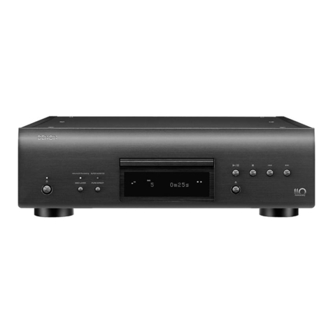
Denon
Denon DVD-2200 User manual

Denon
Denon DVD-1940 User manual

Denon
Denon DCD-100 User manual

Denon
Denon DVM-745 User manual

Denon
Denon DVD-A1XV User manual

Denon
Denon DN-D9000 User manual

Denon
Denon DCD-625 II User manual

Denon
Denon DN-D4000 User manual