Yamaha CD S2000 - SACD Player User manual

■CONTENTS
TO SERVICE PERSONNEL ...................................... 2–3
PREVENTION OF ELECTROSTATIC DISCHARGE .... 4
FRONT PANEL .............................................................. 5
REAR PANELS .......................................................... 5–7
REMOTE CONTROL PANEL ........................................ 8
SPECIFICATIONS / 参考仕様 ...................................... 8–9
INTERNAL VIEW ........................................................... 9
DISASSEMBLY PROCEDURES /分解手順 ........... 10–16
TEST MODE / テストモード .......................................... 17
UPDATING FIRMWARE / ファームウェアの書き込み
............................................................................ 18–24
DISPLAY DATA ........................................................... 25
IC DATA ................................................................. 26–28
PIN CONNECTION DIAGRAMS ............................ 29–30
BLOCK DIAGRAM ....................................................... 31
PRINTED CIRCUIT BOARDS................................ 32–40
SCHEMATIC DIAGRAMS ...................................... 41–45
REPLACEMENT PARTS LIST .............................. 47–58
REMOTE CONTROL.................................................... 59
101078
SERVICE MANUAL
SUPER AUDIO CD PLAYER
2007 All rights reserved.
This manual is copyrighted by YAMAHA and may not be copied or
redistributed either in print or electronically without permission.
P.O.Box 1, Hamamatsu, Japan
'07.12
IMPORTANT NOTICE
This manual has been provided for the use of authorized YAMAHA Retailers and their service personnel.
It has been assumed that basic service procedures inherent to the industry, and more specifically YAMAHA Products, are already
known and understood by the users, and have therefore not been restated.
WARNING: Failure to follow appropriate service and safety procedures when servicing this product may result in personal
injury, destruction of expensive components, and failure of the product to perform as specified. For these reasons,
we advise all YAMAHA product owners that any service required should be performed by an authorized
YAMAHA Retailer or the appointed service representative.
IMPORTANT: The presentation or sale of this manual to any individual or firm does not constitute authorization, certification or
recognition of any applicable technical capabilities, or establish a principle-agent relationship of any form.
The data provided is believed to be accurate and applicable to the unit(s) indicated on the cover. The research, engineering, and
service departments of YAMAHA are continually striving to improve YAMAHA products. Modifications are, therefore, inevitable
and specifications are subject to change without notice or obligation to retrofit. Should any discrepancy appear to exist, please
contact the distributor's Service Division.
WARNING: Static discharges can destroy expensive components. Discharge any static electricity your body may have
accumulated by grounding yourself to the ground buss in the unit (heavy gauge black wires connect to this buss).
IMPORTANT: Turn the unit OFF during disassembly and part replacement. Recheck all work before you apply power to the unit.
CD-S2000
CD-S2000
w
w
w
.
x
i
a
o
y
u
1
6
3
.
c
o
m
Q
Q
3
7
6
3
1
5
1
5
0
9
9
2
8
9
4
2
9
8
T
E
L
1
3
9
4
2
2
9
6
5
1
3
9
9
2
8
9
4
2
9
8
0
5
1
5
1
3
6
7
3
Q
Q
TEL 13942296513 QQ 376315150 892498299
http://www.xiaoyu163.com

2
CD-S2000
CD-S2000
WALL
OUTLET
EQUIPMENT
UNDER TEST
AC LEAKAGE
TESTER OR
EQUIVALENT
INSULATING
TABLE
WARNING: CHEMICAL CONTENT NOTICE!
This product contains chemicals known to the State of California to cause cancer, or birth defects or other reproductive
harm.
DO NOT PLACE SOLDER, ELECTRICAL/ELECTRONIC OR PLASTIC COMPONENTS IN YOUR MOUTH FOR ANY
REASON WHAT SO EVER!
Avoid prolonged, unprotected contact between solder and your skin! When soldering, do not inhale solder fumes or expose
eyes to solder/flux vapor!
If you come in contact with solder or components located inside the enclosure of this product, wash your hands before
handling food.
1. Critical Components Information
Components having special characteristics are marked s
and must be replaced with parts having specifications equal
to those originally installed.
2. Leakage Current Measurement (For 120V Models Only)
When service has been completed, it is imperative to verify
that all exposed conductive surfaces are properly insulated
from supply circuits.
●Meter impedance should be equivalent to 1500 ohms shunted
by 0.15µF.
●Leakage current must not exceed 0.5mA.
●Be sure to test for leakage with the AC plug in both polarities.
本機に搭載されているすべての基板およびハンダ付けによる接合
部は無鉛ハンダでハンダ付けされています。
無鉛ハンダにはいくつかの種類がありますが、修理時には下記の
ような無鉛ハンダの使用を推奨します。
・ Sn+Ag+Cu(錫+銀+銅)
・ Sn+Cu(錫+銅)
・ Sn+Zn+Bi(錫+亜鉛+ビスマス)
注意:
無鉛ハンダの融点温度は通常の鉛入りハンダに比べ30〜40℃
程度高くなっていますので、それぞれのハンダに合ったハンダ
ごてをご使用ください。
All of the P.C.B.s installed in this unit and solder joints are
soldered using the lead free solder.
Among some types of lead free solder currently available,
it is recommended to use one of the following types for the
repair work.
• Sn + Ag + Cu (tin + silver + copper)
• Sn + Cu (tin + copper)
• Sn + Zn + Bi (tin + zinc + bismuth)
Caution:
As the melting point temperature of the lead free solder is
about 30°C to 40°C (50°F to 70°F) higher than that of the lead
solder, be sure to use a soldering iron suitable to each solder.
About lead free solder / 無鉛ハンダについて
■TO SERVICE PERSONNEL
WARNING: Laser Safety
This product contains a laser beam component. This component may emit invisible, as well as visible radiation,
which may cause eye damage. To protect your eyes and skin from laser radiation, the following precautions must be
used during servicing of the unit.
1) When testing and/or repairing any component within the product, keep your eyes and skin more than 30 cm away from
the laser pick-up unit at all times. Do not stare at the laser beam at any time.
2) Do not attempt to readjust, disassemble or repair the laser pick-up, unless noted elsewhere in this manual.
3) CAUTION : Use of controls, adjustments or performance of procedures other than those specified herein may result in
hazardous radiation exposure.
Laser Emitting conditions:
1) When the top cover is removed, and the STANDBY/ON SW is turned to the “ON” position, the laser component will emit
a beam for several seconds to detect if a disc is present. During this time (5-10 sec.) the laser may radiate through the
lens of the laser pick-up unit. Do not attempt any servicing during this period!
If no disc is detected, the laser will stop emitting the beam. When a disc is loaded, you will not be exposed to any laser
emissions.
2) The laser power level can be adjusted with the VR on the pick-up PWB, however, this level has been set by the factory
prior to shipping from the factory. Do not adjust this laser level control unless instruction is provided elsewhere in this
manual. Adjustment of this control can increase the laser emission level from the device.
w
w
w
.
x
i
a
o
y
u
1
6
3
.
c
o
m
Q
Q
3
7
6
3
1
5
1
5
0
9
9
2
8
9
4
2
9
8
T
E
L
1
3
9
4
2
2
9
6
5
1
3
9
9
2
8
9
4
2
9
8
0
5
1
5
1
3
6
7
3
Q
Q
TEL 13942296513 QQ 376315150 892498299
http://www.xiaoyu163.com

3
CD-S2000
CD-S2000
• Material:
SA-CD Semiconductor laser (AlGaInP)
CD Semiconductor laser (AlGaAs)
• Wavelength:
SA-CD 650 nm
CD 780 nm
Warning for power supply
The primary side of the power supply carries live mains voltage when the player is connected to the mains even when
the player is switched off !
This primary area is not shielded so it is possible to touch copper tracks and/or components when servicing the player.
Service personnel have to take precautions to prevent touching this area or components in this area.
Note:
The screws on the DVD mechanism may never be touched, removed or re-adjusted.
Handle the DVD mechanism with care when the unit has to be exchanged!
The DVD mechanism is very sensitive for dropping or giving shocks.
Laser Diode Properties
• Laser Output:
SA-CD 5 mW (max.)
CD 7 mW (max.)
B, G models
w
w
w
.
x
i
a
o
y
u
1
6
3
.
c
o
m
Q
Q
3
7
6
3
1
5
1
5
0
9
9
2
8
9
4
2
9
8
T
E
L
1
3
9
4
2
2
9
6
5
1
3
9
9
2
8
9
4
2
9
8
0
5
1
5
1
3
6
7
3
Q
Q
TEL 13942296513 QQ 376315150 892498299
http://www.xiaoyu163.com

4
CD-S2000
CD-S2000
■PREVENTION OF ELECTROSTATIC DISCHARGE
Some semiconductor (solid state) devices can be damaged easily by static electricity. Such components commonly are called
Electrostatically Sensitive (ES) Devices. Examples of typical ES devices are integrated circuits and some field-effect transis-
tors and semiconductor “chip” components. The following techniques should be used to help reduce the incidence of compo-
nent damage caused by electro static discharge (ESD).
1. Immediately before handling any semiconductor component or semiconductor-equipped assembly, drain off any ESD on
your body by touching a known earth ground. Alternatively, obtain and wear a commercially available discharging ESD wrist
strap, which should be removed for potential shock reasons prior to applying power to the unit under test.
2. After removing an electrical assembly equipped with ES devices, place the assembly on a conductive surface such as
aluminum foil, to prevent electrostatic charge buildup or exposure of the assembly.
3. Use only a grounded-tip soldering iron to solder or unsolder ES devices.
4. Use only an anti-static solder removal device. Some solder removal devices not classified as “anti-static (ESD protected)”
can generate electrical charge sufficient to damage ES devices.
5. Do not use freon-propelled chemicals. These can generate electrical charges sufficient to damage ES devices.
6. Do not remove a replacement ES device from its protective package until immediately before you are ready to install it. (Most
replacement ES devices are packaged with leads electrically shorted together by conductive foam, aluminum foil or compa-
rable conductive material).
7. Immediately before removing the protective material from the leads of a replacement ES divice, touch the protective mate-
rial to the chassis or circuit assembly into which the device will be installed.
CAUTION: Be sure no power is applied to the chassis or circuit, and observe all other safety precautions.
8. Minimize bodily motions when handling unpackaged replacement ES devices. (Otherwise harmless motion such as brush-
ing together of your fabric clothes or lifting of your foot from a carpeted floor can generate static electricity (ESD) sufficient
to damage an ES device).
Grounding for electrostatic breakdown prevention
1. Human body grounding.
Use the antistatic wrist strap to discharge the static electricity from your body.
2. Work table grounding.
Put a conductive material (sheet) or steel sheet on the area where the optical pickup is placed and ground the sheet.
Caution:
The static electricity of your clothes will not be grounded through the wrist strap. So take care not to let your clothes touch the
optical pickup.
1M-ohms
Conductive material
(sheet) or steel sheet
Anti-static wrist strap
w
w
w
.
x
i
a
o
y
u
1
6
3
.
c
o
m
Q
Q
3
7
6
3
1
5
1
5
0
9
9
2
8
9
4
2
9
8
T
E
L
1
3
9
4
2
2
9
6
5
1
3
9
9
2
8
9
4
2
9
8
0
5
1
5
1
3
6
7
3
Q
Q
TEL 13942296513 QQ 376315150 892498299
http://www.xiaoyu163.com

5
CD-S2000
CD-S2000
■FRONT PANEL
CD-S2000 (U, C, R, T, K, A, B, G, L, J models)
■REAR PANELS
CD-S2000 (U, C models)
CD-S2000 (R model)
w
w
w
.
x
i
a
o
y
u
1
6
3
.
c
o
m
Q
Q
3
7
6
3
1
5
1
5
0
9
9
2
8
9
4
2
9
8
T
E
L
1
3
9
4
2
2
9
6
5
1
3
9
9
2
8
9
4
2
9
8
0
5
1
5
1
3
6
7
3
Q
Q
TEL 13942296513 QQ 376315150 892498299
http://www.xiaoyu163.com

8
CD-S2000
CD-S2000
■Audio Section / オーディオ部
Frequency Response /周波数特性
SA-CD .......................................................... 2 Hz to 50 kHz (-3 dB)
CD ............................................................................. 2 Hz to 20 kHz
Total Harmonic Distortion + Noise (1 kHz) /高調波歪率(1kHz)
SA-CD ................................................................... 0.0017 % or less
CD ............................................................................ 0.002 % or less
Signal to Noise Ratio /信号対雑音比 (IHF-A Network)
................................................................................. 116 dB or more
Dynamic Range / ダイナミックレンジ
SA-CD ...................................................................... 110 dB or more
CD ............................................................................ 100 dB or more
Output Voltage (1 kHz, 0 dB) / 出力電圧(1kHz、0dB)
........................................................................................ 2.0 ±0.3 V
■General / 総合
Power Supply /電源電圧
U, C models .......................................................... AC 120 V, 60 Hz
R, L models ........................ AC 110/120/220/230-240 V, 50/60 Hz
T model ................................................................. AC 220 V, 50 Hz
K model ................................................................. AC 220 V, 60 Hz
A model ................................................................. AC 240 V, 50 Hz
B, G models .......................................................... AC 230 V, 50 Hz
J model ........................................................... AC 100 V, 50/60 Hz
Power Consumption/ 消費電力
U, C, R, T, K, A, B, G, L models ............................................. 30 W
J model .................................................................................... 25 W
Off-state Power Consumption/ パワーOFF時消費電力
................................................................................................... 0 W
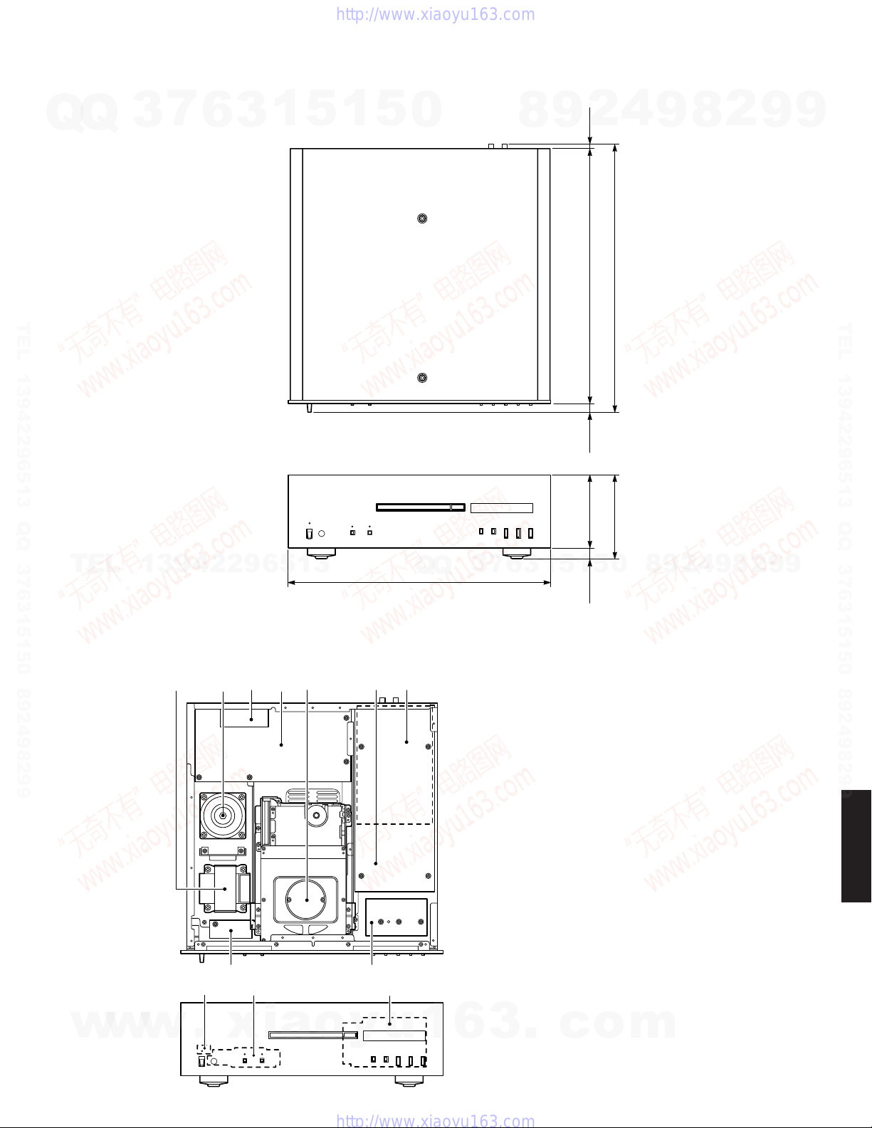
Dimensions (W x H x D) /寸法(幅×高さ×奥行き)
.......................... 435 x 137 x 440 mm (17-1/8”x 5-3/8”x 17-5/16”)
Weight /質量
......................................................................... 15 kg (33 lbs. 1 oz.)
Finish/仕上げ
Black color ................................ U, C, R, T, K, A, B, G, L, J models
Silver color ................................ U, C, R, T, K, A, B, G, L, J models
Accessories /付属品
Remote control x 1, Battery (R6, AA, UM-3) x 2, Audio pin cable (1.5 m)
x 1, Power cable (2 m) x 1
* Specifications are subject to change without notice due to product
improvements.
※ 参考仕様および外観は予告なく変更されることがあります。
■SPECIFICATIONS / 参考仕様
U .......... U.S.A. model
C .......... Canadian model
R .......... General model
T .......... Chinese model
K .......... Korean model
A .......... Australian model
B .......... British model
G .......... European model
L .......... Singapore model
J ........... Japanese model
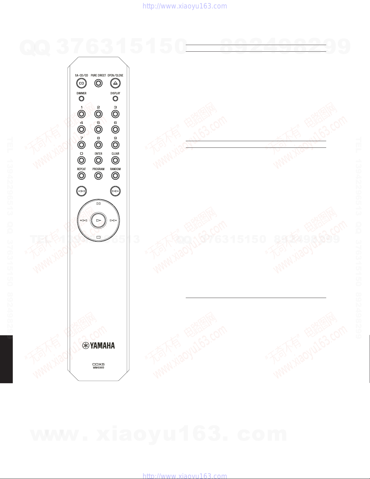
■REMOTE CONTROL PANEL
CDX5
w
w
w
.
x
i
a
o
y
u
1
6
3
.
c
o
m
Q
Q
3
7
6
3
1
5
1
5
0
9
9
2
8
9
4
2
9
8
T
E
L
1
3
9
4
2
2
9
6
5
1
3
9
9
2
8
9
4
2
9
8
0
5
1
5
1
3
6
7
3
Q
Q
TEL 13942296513 QQ 376315150 892498299
http://www.xiaoyu163.com

9
CD-S2000
CD-S2000
435 (17-1/8")
137 (5-3/8") 440 (17-5/16")
418 (16-7/16")120 (4-3/4") 8
(5/16")
14
(9/16")
17
(11/16")
•DIMENSIONS / 寸法図
Unit: mm (inch)
単位:mm(インチ)
■INTERNAL VIEW
1POWER TRANSFORMER for DIGITAL/ LOADER
2POWER TRANSFORMER for AUDIO
3POWER (2) P.C.B. (R, L models)
4POWER (1) P.C.B.
5LOADER ASS'Y
6AUDIO P.C.B.
7DIGITAL (1) P.C.B.
8DIGITAL (5) P.C.B.
9POWER (3) P.C.B.
0DIGITAL (4) P.C.B.
ADIGITAL (3) P.C.B.
BDIGITAL (2) P.C.B.
23 45 6 7
8
B
9
0A
1
w
w
w
.
x
i
a
o
y
u
1
6
3
.
c
o
m
Q
Q
3
7
6
3
1
5
1
5
0
9
9
2
8
9
4
2
9
8
T
E
L
1
3
9
4
2
2
9
6
5
1
3
9
9
2
8
9
4
2
9
8
0
5
1
5
1
3
6
7
3
Q
Q
TEL 13942296513 QQ 376315150 892498299
http://www.xiaoyu163.com

10
CD-S2000
CD-S2000
■DISASSEMBLY PROCEDURES / 分解手順
Fig. 1
(Remove parts in the order as numbered.)
Disconnect the power cable from the AC outlet.
1. Removal of Panel Side L/R
a. Remove 2 screws (1), coned disc spring L and washer
side. (Fig. 1)
b. Lift the panel side L a little, release hooks at 3 locations
and then remove the panel side L. (Fig. 1)
c. Remove 2 screws (2) and then remove 2 washers.
(Fig. 1)
d. Lift the panel side R a little, release hooks at 3 loca-
tions and remove the panel side R. (Fig. 1)
2. Removal of Top Cover
a. Remove 7 screws (3), 2 screws (4) and 2 screws
(5). (Fig. 1)
b. Remove the top cover. (Fig. 1)
(番号順に部品を取り外してください。)
AC電源コンセントから、電源コードを抜いてください。
1. パネルサイドL/Rの外し方
a. 1のネジ2本、サラバネL、ワッシャーサイドを外しま
す。(Fig.1)
b. パネルサイドLを少し持ち上げ、3ヶ所のフックを外
し、パネルサイドLを取り外します。(Fig.1)
c. 2のネジ2本を外し、ワッシャーサイド2個を外しま
す。(Fig.1)
d. パネルサイドRを少し持ち上げ、3ヶ所のフックを外
し、パネルサイドRを取り外します。(Fig.1)
2. トップカバーの外し方
a. 3ネジ7本、4のネジ2本、5のネジ2本を外します。
(Fig.1)
b. トップカバーを取り外します。(Fig.1)
Panel side L
パネルサイドL
Panel side R
パネルサイドR
Washer side
ワッシャーサイド
Washer side
ワッシャーサイド
Coned disc spring L
サラバネL
Coned disc spring L
サラバネL
Front panel
フロントパネル
Top cover
トップカバー
7
6
7
3
1
3
45
2
Hook
フック
Hook
フック
"POWER ON / OFF" switch
POWERON/OFFスイッチ
Hook
フック
Lid
リッド
w
w
w
.
x
i
a
o
y
u
1
6
3
.
c
o
m
Q
Q
3
7
6
3
1
5
1
5
0
9
9
2
8
9
4
2
9
8
T
E
L
1
3
9
4
2
2
9
6
5
1
3
9
9
2
8
9
4
2
9
8
0
5
1
5
1
3
6
7
3
Q
Q
TEL 13942296513 QQ 376315150 892498299
http://www.xiaoyu163.com

11
CD-S2000
CD-S2000
Fig. 2
3. フロントパネルの外し方
a. マイナスドライバーで底面のスライダーを下図の矢印
の方向に動かします。(Fig.2)
※ このとき、トレーは押し出されません。
b. トレイの後方を押し、トレイを押し出します。(Fig.3)
c. 6のネジ2本を外し、リッドを取り外します。(Fig.1)
d. トレイの前方を押し、トレイを閉じます。
e. 7のネジ8本を外します。(Fig.1)
f. POWERON/OFFスイッチをONにします。
g. POWERON/OFFスイッチに傷がつかないようフロ
ントパネルを前方へゆっくり取り外します。(Fig.1)
Fig. 3
3. Removal of Front Panel
a. Using a flatblade screwdriver, move the slider at the bot-
tom in the direction of the arrow shown below. (Fig. 2)
* At this time, the tray is not pushed out.
b. Push out the tray by pushing its rear. (Fig. 3)
c. Remove 2 screws (6) and then remove the lid. (Fig. 1)
d. Close the tray by pushing its front.
e. Remove 8 screws (7). (Fig. 1)
f. Set the “POWER ON/OFF”switch to the ON position.
g. Remove the front panel forward gradually, using care
not to cause any damage to the “POWER ON/OFF”
switch. (Fig. 1)
Flatblade screwdriver
マイナスドライバー
Tray
トレイ
w
w
w
.
x
i
a
o
y
u
1
6
3
.
c
o
m
Q
Q
3
7
6
3
1
5
1
5
0
9
9
2
8
9
4
2
9
8
T
E
L
1
3
9
4
2
2
9
6
5
1
3
9
9
2
8
9
4
2
9
8
0
5
1
5
1
3
6
7
3
Q
Q
TEL 13942296513 QQ 376315150 892498299
http://www.xiaoyu163.com

12
CD-S2000
CD-S2000
4. フロントフレームASSYの外し方
a. 8のネジ4本、9のネジ2本を外し、フレームトップを
取り外します。(Fig.4)
b. 0のネジ9本を外します。(Fig.4)
c. CB601、CB902を外します。(Fig.4)
d. フロントフレームASSYを取り外します。(Fig.4)
5. AUDIOP.C.B.の外し方
a. Aのネジ6本を外します。(Fig.4)
b. Bのネジ4本、Cのネジ4本を外します。(Fig.5)
c. CB1-2、CB5-6を外します。(Fig.4)
※ CB5、CB6を取り付ける場合、必ずCB5側へBlue/
Black色のケーブル、CB6側へRed/Black色のケー
ブルを取り付けてください。
d. AUDIOP.C.B.の前方を持ち上げ、取り外します。
(Fig.4)
Fig. 4
4. Removal of Front Frame ass’y
a. Remove 4 screws (8), 2 screws (9) (B, G models) and
then remove the frame top. (Fig. 4)
b. Remove 9 screws (0). (Fig. 4)
c. Remove CB601 and CB902. (Fig. 4)
d. Remove the front frame ass’y. (Fig. 4)
5. Removal of AUDIO P.C.B.
a. Remove 6 screws (A). (Fig. 4)
b. Remove 4 screws (B) and 4 screws (C). (Fig. 5)
c. Remove CB1-2 and CB5-6. (Fig. 4)
* When installing CB5 and CB6, be sure to con-
nect the Blue/Black color cable to CB5 and the
Red/Black cable to the CB6.
d. Lift the front of AUDIO P.C.B. and then remove it. (Fig. 4)
Frame top
フレームトップ
AUDIO P.C.B.
(B, G, J models)
Loader ass'y
ローダーASSY
Front frame ass'y
フロントフレームASSY
Support AUDIO
サポートAUDIO
D
A
8
H
F
G
E
E
8
9
A
0
0
00
D
CB301
CB302
CB612
CB903
CB601
CB902
CB1
CB2
CB5
CB6
Frame mecha L
フレームメカL
Frame mecha R
フレームメカR
Push rivet
プッシュリベット
Push rivet
プッシュリベット
Support F
サポートF
Support F
サポートF
w
w
w
.
x
i
a
o
y
u
1
6
3
.
c
o
m
Q
Q
3
7
6
3
1
5
1
5
0
9
9
2
8
9
4
2
9
8
T
E
L
1
3
9
4
2
2
9
6
5
1
3
9
9
2
8
9
4
2
9
8
0
5
1
5
1
3
6
7
3
Q
Q
TEL 13942296513 QQ 376315150 892498299
http://www.xiaoyu163.com

CD-S2000
13
AUDIOP.C.B.をチェックをする場合には:
・ 本機の上にゴムシートと布を敷き、その上にP.C.B.を
裏返しに置いてチェックします。(Fig.6)
・ 外したケーブル(コネクター)をすべて接続します。
ただし次の区間は、サービス用延長ケーブルを使用し
てください。
AUDIOP.C.B.:CB2_DIGITALP.C.B.:CB303
12P、450mmP=1.25(MF112450)
・ フラットケーブルを接続する際、極性に注意してくだ
さい。
・ 本機ではP.C.B.のアースがリアパネルおよびシャーシ
に接続されています。これらのP.C.B.をリアパネルよ
り取り外した場合は、アース線等でアースポイントを
リアパネルまたはシャーシに接続してください。
(Fig.6)
Fig. 5
When checking the AUDIO P.C.B.:
• Put the rubber sheet and cloth over this unit. Then
place the P.C.B.s upside down on the cloth and
check it. (Fig. 6)
• Reconnect all cables (connectors) that have been
disconnected.
Be sure to use the extension cable before servicing
the following section.
AUDIO P.C.B.: CB2_DIGITAL P.C.B.: CB303
12P, 450mm P=1.25 (MF112450)
• When connecting the flexible flat cable, be careful
with polarity.
• In this unit, the ground of P.C.B.s shown below is
connected to the rear panel and chassis. When these
P.C.B.s are removed from the rear panel, connect the
ground point to the rear panel or chassis, using a
ground lead wire or the like. (Fig. 6)
6. ローダーASSYの外し方
a. Dのネジ4本を外し、サポートAUDIOを取り外しま
す。(Fig.4)
b. CB301-302、CB612、CB903を外します。(Fig.4)
c. Eのネジ4本を外します。(Fig.4)
d. プッシュリベットを外し、サポートFを取り外します。
(Fig.4)
e. Fのネジ2本を外し、フレームメカLを取り外します。
(Fig.4)
f. Gのネジ2本を外し、フレームメカRを取り外します。
(Fig.4)
g. Hのネジ2本を外し、ローダーASSYを取り外します。
(Fig.4)
● ローダーASSYを取り付ける場合:
ローダーASSYを取り付ける場合には、フロントパネル
とリッドの隙間が上下左右同じになるようにローダー
ASSYの傾きを調整してください。
1. Iのネジ2本、Jのネジ2本を緩めます。(Fig.7)
2. サポートFの平らな面を上向きにします。(Fig.7)
3. 前面から見て、リッドの位置を確認します。(Fig.7)
4. リッドの傾斜が高い側のネジ(下図の場合、Jのネ
ジ)を締めます。(Fig.7)
5. リッドの傾斜が低い側のサポートFを時計回りに
ゆっくり回し、リッドの傾きが水平な位置になるよ
うにします。(Fig.7)
6. リッドの位置が水平の位置でネジ(下図の場合、I
のネジ)を締めます。(Fig.7)
このとき上方向へ位置を変更する場合には、次にJ
のネジを緩め、サポートFを時計回りにゆっくり回
します。
※ 調整は必ずどちらか一方から行ってください。
7. トレイの開閉を数回行い、フロントパネルとリッド
の隙間が上下左右同じであることを確認します。
6. Removal of Loader ass’y
a. Remove 4 screws (D) and then remove the support
audio. (Fig. 4)
b. Remove CB301-302, CB612 and CB903. (Fig. 4)
c. Remove 4 screws (E). (Fig. 4)
d. Remove push rivet and then remove the support F.
(Fig. 4)
e. Remove 2 screws (F) and then the frame mecha L.
(Fig. 4)
f. Remove 2 screws (G) and then remove the frame
mecha R. (Fig. 4)
g. Remove 2 screws (H) and then remove the loader
ass’y. (Fig. 4)
●When installing the Loader Ass’y:
When installing the loader ass’y, adjust the clearance
between the front panel and lid so that it becomes equal
at the top, bottom, right and left.
1. Loosen 2 screws (I) and 2 screws (J). (Fig. 7)
2. Position the support F on both sides with its flat
portion facing upward. (Fig. 7)
3. Viewing from the front, confirm the lid position. (Fig. 7)
4. Tighten the screws on the side with higher lid inclina-
tion (screws (J) in the case shown below). (Fig. 7)
5. Turn the support F on the side with lower lid inclina-
tion clockwise gradually until the lid is positioned
horizontally. (Fig. 7)
6. With the lid adjusted at the horizontal position,
tighten other screws (screws (I) in the case
shown below). (Fig. 7) To change the position up-
ward at this time, loosen screws (J) and then turn
the support F clockwise gradually.
* Be sure to make adjustment from either side only.
7. Repeat opening and closing the tray some times
and confirm to make sure that the same clearance
between the front panel and lid is obtained at the
top, bottom, right and left.
CB C M
L PO
R, L models
Fig. 6
AUDIO P.C.B.
DIGITAL P.C.B.
CB303
CB2
Rubber sheet and cloth
ゴムシートと布
Ground lead
リード線
ST1
FG
Ground lead
リード線
MF112450
Fig. 7
Lid
リッド
Support F
サポートF
Flat portion
平らな面
I
I
J
Support F
サポートF
Flat portion
平らな面
J
w
w
w
.
x
i
a
o
y
u
1
6
3
.
c
o
m
Q
Q
3
7
6
3
1
5
1
5
0
9
9
2
8
9
4
2
9
8
T
E
L
1
3
9
4
2
2
9
6
5
1
3
9
9
2
8
9
4
2
9
8
0
5
1
5
1
3
6
7
3
Q
Q
TEL 13942296513 QQ 376315150 892498299
http://www.xiaoyu163.com

CD-S2000
14
Use a clip or other item to ground
the unit.
クリップ等でアースしてください。
Clip
クリップ
Terminal side
端子面
Unlocked
ロック解除
Locked
ロック
Flexible flat cable
カード電線
Flexible flat cable
カード電線
13 mm
(1/2")
CN101
CN101
Q
Q
Module board
モジュール基板
CN101
CN102
CN103
7. DIGITALP.C.B.の外し方
a. Kのネジ3本を外します。(Fig.8)
b. Lのネジ4本を外します。(Fig.5)
c. CB610-611、CB901を外します。(Fig.8)
d. DIGITALP.C.B.を取り外します。(Fig.8)
8. POWER(1)P.C.B.の外し方
a. Nのネジ4本を外します。(Fig.8)
b. Oのネジ2本、Pのネジ2本を外します。(Fig.5)
c. CB603、CB605-607、CB615を外します。(Fig.8)
d. POWER(1)P.C.B.を取り外します。(Fig.8)
7. Removal of DIGITAL P.C.B.
a. Remove 3 screws (K). (Fig. 8)
b. Remove 4 screws (L). (Fig. 5)
c. Remove CB610-611 and CB901. (Fig. 8)
d. Remove the DIGITAL P.C.B.. (Fig. 8)
8. Removal of POWER (2) P.C.B.
(R and L models)
a. Remove 2 screws (M). (Fig. 5)
b. Remove CB602 and CB604. (Fig. 8)
c. Remove the POWER (2) P.C.B.. (Fig. 8)
9. Removal of POWER (1) P.C.B.
c. Remove 4 screws (N). (Fig. 8)
b. Remove 2 screws (O) and 2 screws (P). (Fig. 5)
c. Remove CB603, CB605-607 and CB615. (Fig. 8)
d. Remove the POWER (1) P.C.B.. (Fig. 8)
●Disassembly of Loader Ass’y
1. Removal of Module Board
a. Remove CN102 and CN103. (Fig. 9)
b. Unlock CN101 and then disconnect the flexible flat
cable, and ground the terminal face of the flexible
flat cable with a clip or the like. (Fig. 9)
c. Remove 5 screws (Q). (Fig. 9)
d. Remove the module board. (Fig. 9)
Fig. 8
DIGITAL P.C.B.
K
N
N
K
CB611
CB610
CB603
CB605
CB606
CB607
CB615
CB901
POWER (1) P.C.B.
● ローダーASSYの分解手順
1. モジュール基板の外し方
a. CN102-103を外します。(Fig.9)
b. CN101のロックを解除してカード電線を外しま
す。次に外したカード電線のクリップ等で端子面を
アースします。(Fig.9)
c. Qのネジ5本を外します。(Fig.9)
d. モジュール基板を取り外します。(Fig.9)
Fig. 9
w
w
w
.
x
i
a
o
y
u
1
6
3
.
c
o
m
Q
Q
3
7
6
3
1
5
1
5
0
9
9
2
8
9
4
2
9
8
T
E
L
1
3
9
4
2
2
9
6
5
1
3
9
9
2
8
9
4
2
9
8
0
5
1
5
1
3
6
7
3
Q
Q
TEL 13942296513 QQ 376315150 892498299
http://www.xiaoyu163.com

15
CD-S2000
CD-S2000
2. Removal of DVD Traverse Mechanism and
Stepping Motor.
* When installing a new DVD traverse mecha-
nism, remove the solder from the shorted
point of pick up unit using an electrostatic
shielding soldering iron.
a. Remove 6 screws (R) and then remove the clamp
ass’y. (Fig. 10)
b. Push out the tray by pushing its rear. (Fig. 10)
c. Remove 2 screws (S). (Fig. 10)
d. Remove the DVD traverse mechanism together
with the holder PU/SA-CD. (Fig. 10)
e. Remove 4 screws (T) and then remove the DVD
traverse mechanism. (Fig. 10)
f. Remove 2 screws (U) and then remove the step-
ping motor. (Fig. 10)
2. DVDトラバースメカおよびステッピングモー
ターの外し方
※ 新しいDVDトラバースメカに交換する場合、
ピックアップユニットのショート箇所のハンダ
を静電気対策ハンダごてで取り除いてくださ
い。
a. Rのネジ6本を外し、クランプASSYを取り外しま
す。(Fig.10)
b. トレイの後方を押し、トレイを押し出します。
(Fig.10)
c. Sのネジ2本を外します。(Fig.10)
d. DVDトラバースメカをホルダーPU/SA-CDと一緒に
取り外します。(Fig.10)
e. Tのネジ4本を外し、DVDトラバースメカを取り外
します。(Fig.10)
f. Uのネジ2本を外し、ステッピングモーターを取り
外します。 (Fig.10)
Stepping motor
ステッピングモーター
U
RR
S
T
DVD Traverse mechanism
DVDトラバースメカ
Holder PU/SA-CD
ホルダーPU/SA-CD
Tray
トレイ
Clamp ass'y
クランプASSY
Fig. 10
w
w
w
.
x
i
a
o
y
u
1
6
3
.
c
o
m
Q
Q
3
7
6
3
1
5
1
5
0
9
9
2
8
9
4
2
9
8
T
E
L
1
3
9
4
2
2
9
6
5
1
3
9
9
2
8
9
4
2
9
8
0
5
1
5
1
3
6
7
3
Q
Q
TEL 13942296513 QQ 376315150 892498299
http://www.xiaoyu163.com

16
CD-S2000
CD-S2000
・ 新しいステッピングモーターを取り付ける場合:
新しいステッピングモーターを取り付ける場合に
は、新しいステッピングモーターのスクリュー部分
にグリスを塗布します。
推奨グリス:PN-397(部品番号:AAX89650)
a. スクリュー部の下図3ヶ所にグリスを塗布しま
す。(Fig.11)
※ 塗布量:3mg±1mg×3ヶ所
b. グリスを塗布した後、ステッピングモーターの
スクリュー部A-B間にグリスを均一に伸ばしま
す。(Fig.12)
※ グリスを均一に伸ばす場合、スクリュー部
にキズをつけないよう十分注意してくださ
い。
※ 糸くずやほこり等が付着した場合、糸くず
やほこり等を取り除いてください。
c. DVDトラバースメカの下図にグリスを塗布しま
す。(Fig.13)
※ 塗布量:2mg±1mg×1ヶ所
・ 新しいステッピングモーター取り付け後の動作確認
すべての部品を取り付けた後、電源を入れて動作確
認を行います。
1. CDを入れて、1曲目と最終曲間のサーチを数回
繰り返し、グリスを馴染ませます。
2. ランダム再生を行い、問題なく再生できるか確
認します。
• When installing a new Stepping Motor:
Before installing a new stepping motor, apply
grease to its screw.
Recommended grease:
PN-397 (Part No.: AAX89650)
a. Apply grease to the screw at 3 points as shown
below. (Fig. 11)
* Amount of grease to be applied:
3mg ±1mg at 3 points
b. After applying grease, spread it evenly between
A and B of the screw of the stepping motor.
(Fig. 12)
* While spreading grease evenly, use full
care not to cause damage to the screw.
* If waste thread, dust, etc. is attached, re-
move it.
c. Apply grease to the DVD traverse mechanism
as shown below. (Fig. 13)
* Amount of grease to be applied:
2 mg ±1mg at 1 point
• Operation check after installing a new stepping
motor
After installing all parts, turn on the power and
check for proper operation.
1. Load CD, repeat the search function between
the first number and the last one some times so
that the grease is settled.
2. Perform random playback and check for proper
operation.
Fig. 11
Fig. 12
Fig. 13
w
w
w
.
x
i
a
o
y
u
1
6
3
.
c
o
m
Q
Q
3
7
6
3
1
5
1
5
0
9
9
2
8
9
4
2
9
8
T
E
L
1
3
9
4
2
2
9
6
5
1
3
9
9
2
8
9
4
2
9
8
0
5
1
5
1
3
6
7
3
Q
Q
TEL 13942296513 QQ 376315150 892498299
http://www.xiaoyu163.com

17
CD-S2000
CD-S2000
"PLAY" key
PLAYキー
"STOP" key
STOPキー
"POWER ON/OFF" switch
POWERON/OFFスイッチ
TEST X0012TEST X0012
TEST X0012
TEST X0012TEST X0012
TEST X0012
■TEST MODE / テストモード
Initial display / 初期表示
The firmware version of the module board is displayed. /
モジュール基板のファームウェアバージョンを表示します。
The firmware version of the microprocessor and its updated data are displayed. /
マイコンのファームウェアバージョンおよび更新日付を表示します。
All segments ON (dimmer 100 %) /
全セグメント点灯(ディマー100%)
All segments OFF / 全セグメント消灯
(Not applied to this model / このモデルには適用されません。)
●Starting Test Mode
To activate the TEST mode, set the “POWER ON/
OFF”switch to the ON position while pressing the
keys of this unit as shown below at the same time.
● テストモード起動
本機の下図に示すキーを同時に押しながらPOWER
ON/OFFスイッチをONにすると、テストモードが起
動します。
When the power is ON
電源オン時
Starting TEST mode
テストモード起動
Firmware version of microprocessor is displayed. /
マイコンのファームウェアバージョン表示
TESTTEST
TESTTEST
TEST
X0012X0012
X0012X0012
X0012
Release the “PLAY”and “STOP keys.
PLAYキーおよびSTOPキーを放す
● テストモードの操作方法
リモコンのDISPLAYキーを押すと、下図の順で表示
が切り替わります。
●Operating Test Mode
Press the “DISPLAY”key on the remote control, and
the display changes in the order as shown below.
TESTTEST
TESTTEST
TEST
X0012X0012
X0012X0012
X0012
71627162
71627162
7162
11
11
1__
__
_1414
1414
14
X0012X0012
X0012X0012
X0012
071001071001
071001071001
071001
The firmware version /
ファームウェアバージョン
XXXXXXXXXXXXXXXXXXXX
XXXXXXXXXX
The updating data /
更新日付
The firmware version /
ファームウェアバージョン
w
w
w
.
x
i
a
o
y
u
1
6
3
.
c
o
m
Q
Q
3
7
6
3
1
5
1
5
0
9
9
2
8
9
4
2
9
8
T
E
L
1
3
9
4
2
2
9
6
5
1
3
9
9
2
8
9
4
2
9
8
0
5
1
5
1
3
6
7
3
Q
Q
TEL 13942296513 QQ 376315150 892498299
http://www.xiaoyu163.com

18
CD-S2000
CD-S2000
• RS232C conversion jig (Part No.: AAX88050)
●Preparation and precautions before starting
the operation
•Download firmware downloader program and
firmware from the specified source to the same
folder of the PC.
•Prepare the above specified RS232C cross
cable.
•While writing, keep the other application software
on the PC closed.
It is also recommended to keep the software on
the task tray closed as well.
■UPDATING FIRMWARE / ファームウェアの書き込み
下記の部品をサービス部品に交換した場合、下記の手順
により最新のファームウェアの書き込みを行ってくださ
い。
DIGITALP.C.B.
DIGITALP.C.B.のマイコン(IC302)
● 必要なツール
・ プログラム書き込み用プログラム
................................................... FlashSta.exe
・ ファームウェア
..................................................CDS2000xx.S
................................................. CDS2000xx.id
・ RS232CクロスケーブルD-sub9pinメス
(仕様)
After replacing the following parts with the replacement
parts, update the latest firmware according to the following
procedure.
DIGITAL P.C.B.
Microprocessor (IC302) of DIGITAL P.C.B.
●Required tools
• Program downloader programs
................................................... FlashSta.exe
• Firmware
.................................................. CDS2000xx.S
................................................. CDS2000xx.id
• RS232C cross cable “D-sub 9 pin female”
(Specifications)
PinNo.2RxD PinNo.2RxD
PinNo.3TxD PinNo.3TxD
PinNo.5GND PinNo.5GND
PinNo.7RTS PinNo.7RTS
PinNo.8CTS PinNo.8CTS
・ RS232C変換冶具(部品番号:AAX88050)
● 操作前の準備と注意
・ PCへ指定のダウンロード先からファームウェア書
き込み用プログラムおよび、ファームウェアを同
じフォルダにダウンロードしてください。
・ RS232Cクロスケーブルは必ず上記仕様のものを
用意してください。
・ 書き込み時は、PC上の他のアプリケーションソフ
トは閉じてください。
さらに、タスクトレイ上にあるソフトも閉じてお
くことを推奨します。
PinNo.2RxD PinNo.2RxD
PinNo.3TxD PinNo.3TxD
PinNo.5GND PinNo.5GND
PinNo.7RTS PinNo.7RTS
PinNo.8CTS PinNo.8CTS
マイコンへの書き込みWriting to the microprocessor
w
w
w
.
x
i
a
o
y
u
1
6
3
.
c
o
m
Q
Q
3
7
6
3
1
5
1
5
0
9
9
2
8
9
4
2
9
8
T
E
L
1
3
9
4
2
2
9
6
5
1
3
9
9
2
8
9
4
2
9
8
0
5
1
5
1
3
6
7
3
Q
Q
TEL 13942296513 QQ 376315150 892498299
http://www.xiaoyu163.com

19
CD-S2000
CD-S2000
Fig. 1
● 操作方法
1. 本機の電源を切り、電源コードをACコンセントから抜
きます。
2. 1のネジ2本を外します。(Fig.1)
3. パネルサイドRを少し持ち上げ、フック3ヶ所を外し、
パネルサイドRを取り外します。(Fig.1)
4. 本機の書き込み用ポートとPCのシリアルポート
(RS232C)を下記のように接続します。(Fig.1)
●Operation Procedure
1. Turn off the power of this unit and disconnect the
power cable from the AC outlet.
2. Remove 2 screws (1). (Fig. 1)
3. Lift the panel side R a little, release hooks at 3 loca-
tions and then remove the panel side R. (Fig. 1)
4. Connect the writing port of the this unit to the serial
port (RS232C) of the PC with RS232C cross cable,
RS232C conversion jig and flexible flat cable as
shown below. (Fig. 1)
"POWER ON/OFF" switch
POWERON/OFFスイッチ
5. 電源コードをACコンセントに接続します。(Fig.1)
6. RS232C変換冶具のリセットスイッチを押しながら、
本機のPOWERON/OFFスイッチをONにします。
(Fig.1)
5. Connect the power cable to the AC outlet. (Fig. 1)
6. While pressing the reset switch of RS232C conver-
sion jig, set the “POWER ON/OFF”switch of this unit
to the ON position. (Fig. 1)
Panel side R
パネルサイドR
1
Hook
フック
RS232C cross cable
RS232Cクロスケーブル
RS232C conversion jig
RS232C変換冶具
Reset switch
リセットスイッチ
Flexible flat cable 9P
カード電線9P
Writing port
書き込み用ポート
Washer side
ワッシャーサイド
Coned disc spring L
サラバネL
w
w
w
.
x
i
a
o
y
u
1
6
3
.
c
o
m
Q
Q
3
7
6
3
1
5
1
5
0
9
9
2
8
9
4
2
9
8
T
E
L
1
3
9
4
2
2
9
6
5
1
3
9
9
2
8
9
4
2
9
8
0
5
1
5
1
3
6
7
3
Q
Q
TEL 13942296513 QQ 376315150 892498299
http://www.xiaoyu163.com

20
CD-S2000
CD-S2000
Fig. 3
Click to open the window
ここをクリックすると
ウィンドウが開きます
8. 送信データ、ポートを選択します。(Fig.2)
・ SelectProgram
Internalflashmemoryを選択します。
・ RS232C
接続しているRS-232Cポートを選択します。
※ ポートの選択はCOM1〜4までが使用できま
す。
COM5以上は使用できませんので、PC側の設
定でCOM1〜4を選択してください。
9. [Refer...]をクリックし、書き込むファームウェアを選
択します。(Fig.3)
※ ID、およびMCUTypeは書き込みファイ
ル選択時、自動的に取り込まれます。
(Fig.3)
[OK]をクリックします。(Fig.3)
8. Select the port and data to be transmitted. (Fig. 2)
· Select Program
Select Internal flash memory
· RS232C
Select the port of RS-232C
* For selection of the port, COM1 to 4 can be
used.
As COM5 or higher port cannot be used, select
out of COM 1 to 4 of the setting on the PC side.
9. Click [Refer...]. And select the firmware name. (Fig. 3)
* The ID code and MCU type
are loaded when the file is se-
lected. (Fig. 3)
Click [OK]. (Fig. 3)
Fig. 2
Select Internal flash memory
Internalflashmemoryを選択します
Select the port of RS-232C
接続しているRS-232Cポートを選択します
7. FlashSta.exeを立ち上げます。
すると下記の画面が表示されます。(Fig.2)
7. Start up FlashSta.exe, the screen will appear as
shown below. (Fig. 2)
w
w
w
.
x
i
a
o
y
u
1
6
3
.
c
o
m
Q
Q
3
7
6
3
1
5
1
5
0
9
9
2
8
9
4
2
9
8
T
E
L
1
3
9
4
2
2
9
6
5
1
3
9
9
2
8
9
4
2
9
8
0
5
1
5
1
3
6
7
3
Q
Q
TEL 13942296513 QQ 376315150 892498299
http://www.xiaoyu163.com
Other manuals for CD S2000 - SACD Player
7
Table of contents
Other Yamaha CD Player manuals

Yamaha
Yamaha DVD-C920 User manual

Yamaha
Yamaha CD-N301 User manual

Yamaha
Yamaha CDC-697 User manual

Yamaha
Yamaha CD-S303 User manual

Yamaha
Yamaha CDX-710 User manual

Yamaha
Yamaha CDX-410U User manual

Yamaha
Yamaha CDX-550 User manual

Yamaha
Yamaha CDC-585 User manual

Yamaha
Yamaha CD-S300 User manual

Yamaha
Yamaha CDC-35 User manual

Yamaha
Yamaha CDX-410U User manual

Yamaha
Yamaha CD-N500 User manual

Yamaha
Yamaha CDV-1200K User manual

Yamaha
Yamaha CDV-1700 User manual

Yamaha
Yamaha CDX-420 User manual

Yamaha
Yamaha CDV-W901 User manual

Yamaha
Yamaha CD-NT670 User manual

Yamaha
Yamaha CDX-710/U/CD-33 User manual

Yamaha
Yamaha CDX-9 User manual

Yamaha
Yamaha CD-S303BL User manual