NGLISH
DEUTSCH
FRANCAIS
ITALIANO
ESPANOL
NEDERLANDS
SVENSKA
PORTUGUES
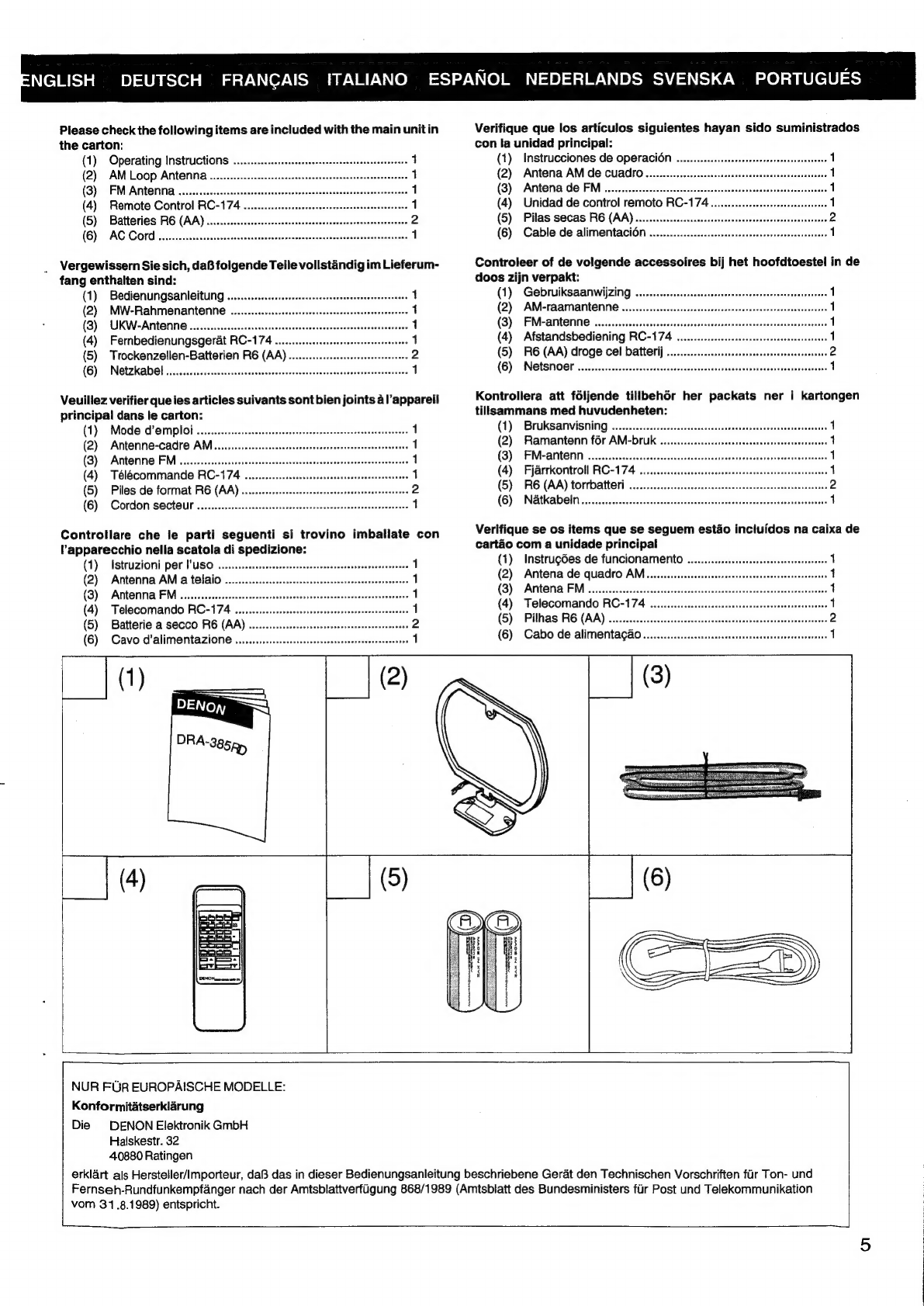
Please
check
the
following
items
are
included
with
the
main
unit
in
Verifique
que
los
articulos
siguientes
hayan
sido
suministrados
the
carton:
con
la
unidad
principal:
(1)
Operating
Instructions
............
1
(1)
Instrucciones
de
OperaciOn
ou...
cccccseeesceesteesseeenaeees
1
(2)
AM
Loop
Antenna.........
1
(2)
Antena
AM
de
CUuadro
.........
et
eeceeeseesenereetsenseenseseaneasee
(3)
FM
Antenna
.........
eee
ee
|
(3)
Antena
de
FM
.........:eeseeeeeseteeeseeee
(4)
Remote
Control
RC-174
......eceeeesceeteeereecees
re
|
(4)
Unidad
de
control
remoto
RC-174
(5)
Batteries
RE
(AA)
...0....sssccseessessntsreasserseeesees
wiwe
(5)
Pilas
secas
RE
(AA)
........:
cc
cesesessrteesneessscaseerseatesesttenees
(6)
AG.
COrd
eicccessesusestieseantiet
a
avscecteseeteeaseeststed
heordescaexrsces
1
(6)
Cable
de
alimentaciOn
..............:cceeseseeescesenseeeseeeeseeesees
Vergewissern
Sie
sich,
daB
folgende
Teile
vollstandig
im
Lieferum-
Controleer
of
de
volgende
accessoires
bij
het
hoofdtoestel
in
de
fang
enthalten
sind:
doos
zijn
verpakt:
(1)
Bedienungsanleituing
.........sscssecceeccseceersecseeceesterseenteases
1
(1)
GebruiksaanwijZing
........ecessscseseseesensssesteeeecssesseeneens
1
(2)
MW-Rahmenantenne
..
|
(2)
AM-raamantenne
(8B)
UKW-ANHENNG
..esscssesssecsessesssssessssesssesscsecneceesaeesceessecesens
1
(3)
FM-antenne
.......eceeeeeen
(4)
Fernbedienungsgerat
RC-174
........eceseseeeseeeseeeeseeensees
1
(4)
Afstandsbediening
RO-174
.........ecsssescscsensseteeenssnsens
1
(5)
Trockenzellen-Batterien
R6
(AA)...
ane
(5)
F6
(AA)
droge
cel
batterij
occ
ssesseneersseensessnens
2
(6)!
iNGtZKADE]
cc.sessessssavsscsdcesstesttie
Scesseosten
Reet
ebaseeetebeateecan
ete
1
(8)
N@tSNOGE
oi.
0c
cccienicestzedcsvesisesceccssecaatacdcdeeseseasassiensdigdsveseees
1
Veuillez
verifier
que
les
articles
suivants
sont
bien
joints
al’appareil
Kontrollera
att
foljende
tillbehér
her
packats
ner
i
kartongen
principal
dans
le
carton:
tillsammans
med
huvudenheten:
(1)
Mode
d'emploi
....cscescesssscssssscsesssssssesseessessessssssessesseenss
{
(1);
(BrukGanviSNling)
eiscccsseiseidscdeccce
iietcscancieciavestevevesnvasveedientss
1
(2)
Antenne-cadre
AM
.uscssscsccessessssssesssessessessessecsncssesstessenass
1
(2)
Ramantenn
fr
AM-DIUK
........csssessessessssesesseerssersesnenseenns
1
(3):
GArntorine:
FM
eiicess.ccstaicsedevseascaseredonetorrseicnacerasctenraaats
1
(3)
FM-Antenn
.......secsessesseeseecssessesssecnessurenssnenssnerarsnsececeassenees
1
(4)
Télecommande
RC-174
..
et
(4)
Fjarrkontroll
RO-174
0...
eecesscceceeeeeeeeseeeeseeeeseneeeneates
1
(5)
Piles
de
format
R6
(AA)...
2
(5)
FRG
(AA)
torrbatteri
....-ssscsesueesssssscsesescesseecececssssnsesseeeey
2
(6)
Cordon
secteur
..........00006
34
(6)
NA&tkAD
GIN
isccccccsssaccscsesceascactiascoussocssssevssacancesccassadadsseivens
1
Controllare
che
le
parti
seguenti
si
trovino
imballate
con
Verifique
se
os
items
que
se
seguem
estao
incluidos
na
caixa
de
Vapparecchio
nella
scatola
di
spedizione:
cartéo
com
a
unidade
principal
(1)
Estruzioni
per
USO
..es.scesssescssecsesecsssessecsnecssecssessseeseeessess
1
(1)
Instrugdes
de
funcionaMento
.........eecssssesesserarssessreenereees
1
(2)
Antenna
AM
a
telaio
....
4
(2)
Antena
de
quadro
AM...
ccssccccseseecssseeseeseteesseetrseceseees
1
(3)
AMterma
FM
cessssscsssssssssssssssssssssssssssessossesssssessecsscesssesessess
1
(3)
AMPS
FM
aicec
esis
csccckeevecesecsectsvessnrticebecnceasdecasnecdeneseasvinses
1
(4)
Telecomando
RC=174
..ssccssssssssssssssssssssssesssseeeeseeesssssseees
1
(4)
Telecomando
RC-174
o....ssssssssssssssesesesescescenereeneeeees
1
(5)
Batterie
a
secco
R6
(AA)
....
2
(5)
Pilhas
R6
(AA)
sds
dutd
baad
tage
ula
edoxtecntonadeestaetenadeiatueasesusivete
2
(6B)
Cavo
d’alimentazione
vccssessccssesscssssessssssesssesecssseecsessees
1
(6)
Cabo
de
alimentagao
......sessesessssccsescntteneenttensecaneenennes
1
[{o%
5
aannemrosnsaee
ae
ENE
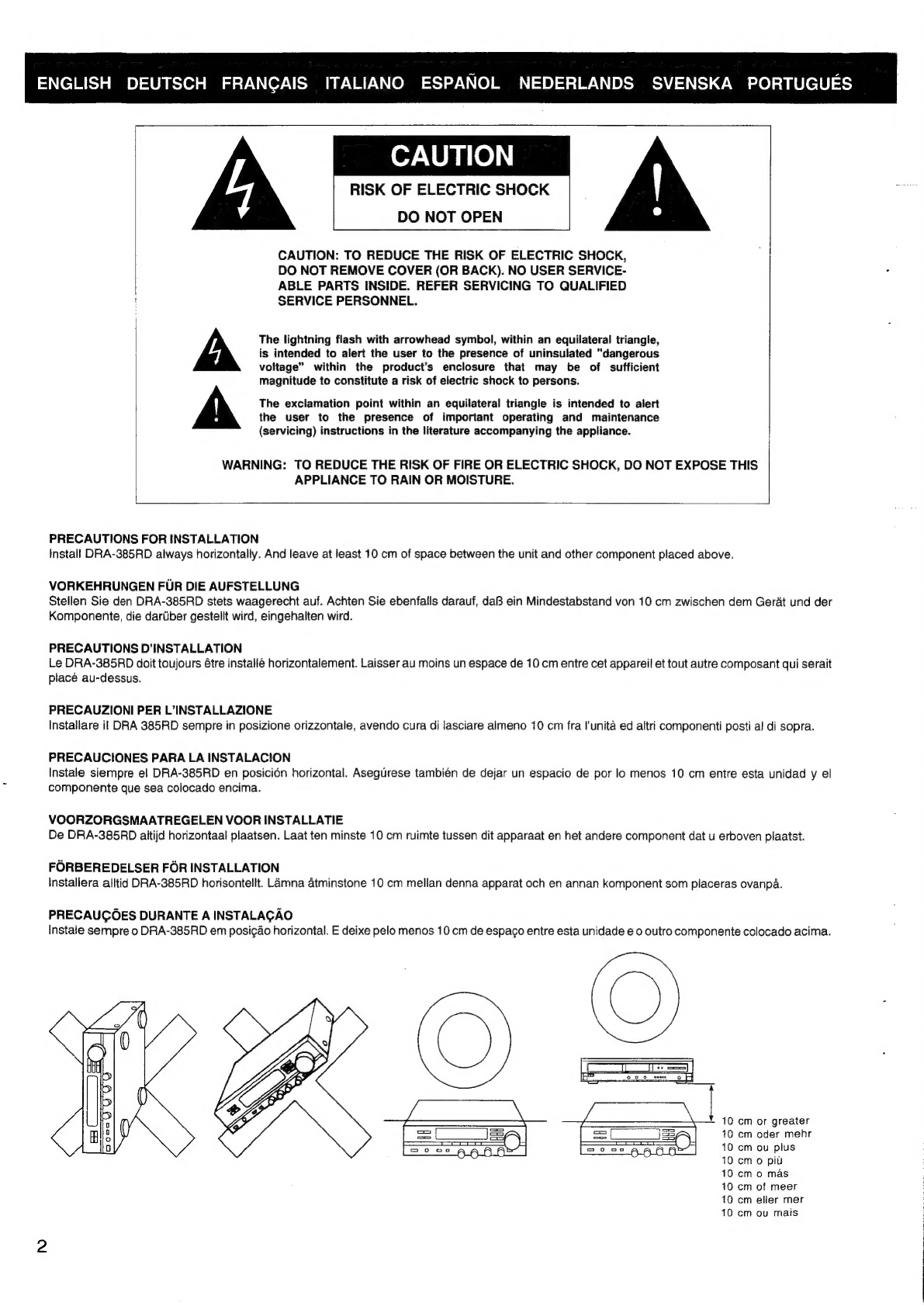
NUR
FUR
EUROPAISCHE
MODELLE:
Konformitatserklarung
Die
DENON
Elektronik
GmbH
Halskestr.
32
40880
Ratingen
erklart
als
Hersteller/Importeur,
daB
das
in
dieser
Bedienungsanleitung
beschriebene
Gerat
den
Technischen
Vorschriften
fir
Ton-
und
Fernseh-Rundfunkempfanger
nach
der
Amtsblattverfigung
868/1989
(Amtsbiatt
des
Bundesministers
fir
Post
und
Telekommunikation
vom
31.8.1989)
entspricht.