9
www.DentalEZ.com 866-DTE-INFO
9
PN: 1045DOC_E
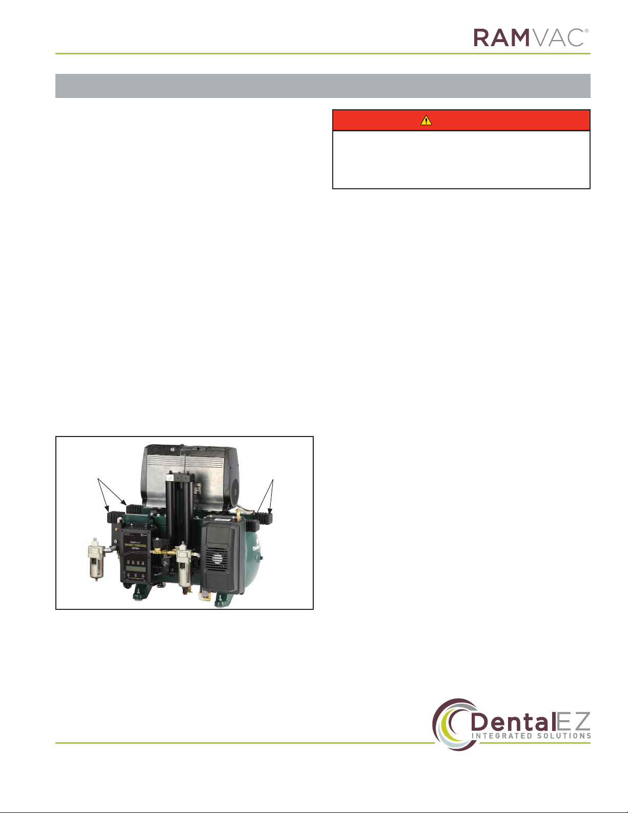
Site Requirements
Before the compressor can be properly installed,
the following utilites must be supplied.
This device requires proper electrical grounding
for safe operation. A licensed electrician should
always complete the electrical portion of the
installation process.
Electrical
• Follow NEC, NFPA 99C, and all local codes.
• Compressors are shipped with a 6-foot
electrical whip of the appropriate size for the
compressor.
• Qualied personnel must install a dedicated
electrical circuit of suicient capacity. See
Section I Introduction, Specications in this
manual for additional electrical information.
• Any means provided to isolate this device
from the supply mains shall isolate all poles
simultaneously.
• The disconnection means and overcurrent
protection are to be provided by the installer
(qualied electrician) in accordance with
applicable local and national electric codes.
This device should always be attached to
a dedicated circuit with appropriate wiring
and circuit protection. If this device is being
installed as a replacement, always have a
licensed electrician inspect the existing facility
electrical and complete the electrical portion of
the device installation.
Plumbing
• Attach drain tubing to tting on bottom of
coalescing lter and direct it into oor drain for
proper disposal of water.
• Connect compressor air outlet to facility
plumbing with provided supply hose (3/8" ×
3/8" MPT, 6 feet in length).
• Install particulate lter to the facility shut-o
valve using plumbing kit connectors provided.
• Install fresh air manifold and connect fresh air
intake kit supplied to external air source per
NFPA 99C recommendations.
• This device should always be installed with
the appropriate plumbing and fresh air intake
systems. If this device is being installed as a
replacement, always have a licensed plumber
inspect the existing facility plumbing and
complete the plumbing portion of the device
installation.
Section II Preinstallation
• To avoid risk of electric shock, this
equipment must only be connected to a
supply mains with protective earth.
WARNING
• This air compressor has been designed to
operate within the following voltage ranges;
115V systems, 103 to 126V AC; 230V systems,
208 to 253V AC. Failure to provide suicient
voltage to this device could result in damage
to electrical components and reduced
service life.
NOTICE
• During the performance of any service
procedures that may involve the
disconnection of a ground wire, take extra
precautions to verify the ground wire has
been properly re-connected. Never leave a
ground wire disconnected, since this can
create a signicant safety issue.
CAUTION