NATIONAL MACHINERY NA2420E User manual

INSTRUCTIONS FOR
COMPRESSOR 24LTR DIRECT DRIVE 2HP
MODEL NO: NA2420E
Thank you for purchasing a National Machinery product. Manufactured to a high standard, this product will, if used according to
these instructions, and properly maintained, give you years of trouble free performance.
IMPORTANT: PLEASE READ THESE INSTRUCTIONS CAREFULLY. NOTE THE SAFE OPERATIONAL REQUIREMENTS, WARNINGS & CAUTIONS. USE
THE PRODUCT CORRECTLY AND WITH CARE FOR THE PURPOSE FOR WHICH IT IS INTENDED. FAILURE TO DO SO MAY CAUSE DAMAGE AND/OR
PERSONAL INJURY AND WILL INVALIDATE THE WARRANTY. KEEP THESE INSTRUCTIONS SAFE FOR FUTURE USE.
Original Language Version
Guide to symbols
Warning: Electricity
Warning: Hot Surface
Warning: Automatic start up
Wear ear protection
Read the instruction manual before use
DO NOT open the air cock before an air hose is attached
DO NOT operate the compressor with enclosure
displaced
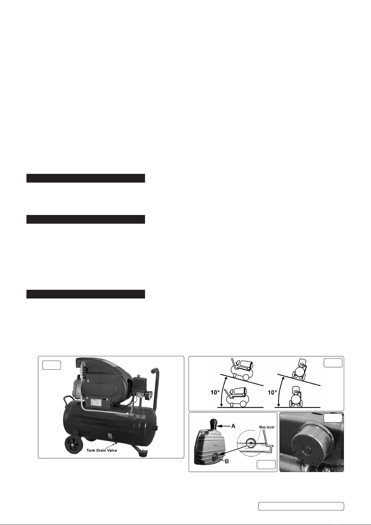
Ensure oil level is correct before rst use
1. SAFETY
1.1. ELECTRICAL SAFETY
WARNING! It is the responsibility of the owner and the operator to read, understand and comply with the following: You must check
all electrical products, before use, to ensure that they are safe. You must inspect power cables, plugs, sockets and any other connectors
for wear or damage. You must ensure that the risk of electric shock is minimised by the installation of appropriate safety devices. A
Residual Current Circuit Breaker (RCCB) should be incorporated in the main distribution board. We also recommend that a Residual
Current Device (RCD) is used. It is particularly important to use an RCD with portable products that are plugged into a supply which is
not protected by an RCCB. If in any doubt consult a qualified electrician. You may obtain a Residual Current Device by contacting your
dealer. You must also read and understand the following instructions concerning electrical safety.
1.1.1. The Electricity at Work Act 1989 requires that all portable electrical appliances, if used on business premises, are tested by a
qualified electrician, using a Portable Appliance Tester (PAT), at least once a year.
1.1.2. The Health & Safety at Work Act 1974 makes owners of electrical appliances responsible for the safe condition of those appliances
and the safety of the appliance operators. If in any doubt about electrical safety, contact a qualified electrician.
1.1.3. Ensure that the insulation on all cables and on the appliance is safe before connecting it to the power supply. See 1.1.1.and 1.1.2.
and use a Portable Appliance Tester.
1.1.4. Ensure that cables are always protected against short circuit and overload.
1.1.5. Regularly inspect power supply cables and plugs for wear or damage and check all connections to ensure that none is loose.
Important: Ensure that the voltage marked on the appliance matches the power supply to be used and that the plug is fitted with the
correct fuse - see fuse rating below.
1.1.6. DO NOT pull or carry the appliance by the power cable.
1.1.7. DO NOT pull the plug from the socket by the cable.
1.1.8. DO NOT use worn or damaged cables, plugs or connectors. Immediately have any faulty item repaired or replaced by a qualified
electrician. When a BS 1363/A UK 3 pin plug is damaged, cut the cable just above the plug and dispose of the plug safely.
Fit a new plug according to the following instructions (UK only).
a) Connect the GREEN/YELLOW earth wire to the earth terminal ‘E’.
b) Connect the BROWN live wire to the live terminal ‘L’.
c) Connect the BLUE neutral wire to the neutral terminal ‘N’.
d) After wiring, check that there are no bare wires, that all wires have been correctly connected, that the cable outer insulation
extends beyond the cable restraint and that the restraint is tight.
Double insulated products, which are always marked with this symbol, are fitted with live (brown)
and neutral (blue) wires only. To rewire, connect the wires as indicated in diagram. DO NOT connect
either wire to the earth terminal.
1.1.9. Products which require more than 13 amps are supplied without a plug. In this case you must contact
a qualified electrician to ensure that a suitably rated supply is available. We recommend that you
discuss the installation of an industrial round pin plug and socket with your electrician.
IMPORTANT! The use of extension leads to connect these compressors to the mains is
not recommended as the resulting voltage drop reduces motor, and therefore pump performance.
1.2. GENERAL SAFETY
Familiarise yourself with the application and limitations of the compressor.
Ensure the compressor is in good order and condition before use. If in any doubt do not use the unit
and contact an electrician/service agent.
WARNING! Compressor must only be serviced by an authorised agent. DO NOT tamper with,
or attempt to adjust, pressure switch or safety valve.
Before moving, or maintaining the compressor ensure it is unplugged from the mains supply and that
the air tank pressure has been vented.
Maintain the compressor in good condition and replace any damaged or worn parts. Use genuine parts only. Unauthorised parts may
be dangerous and will invalidate your warranty.
Read the instructions relating to any accessory to be used with this compressor. Ensure the safe working pressure of any air
appliance used exceeds compressors output pressure. If using a spray gun, check that the area selected for spraying is provided with
an air change/ventilation system.
Ensure the air supply valve is turned off before disconnecting the air supply hose.
RECOMMENDED
FUSE RATING: 13 AMP
NA2420E | Issue 1 20/05/16

Original Language Version
To move the compressor, use the handle only. Maintain unit’s centre of gravity when lifting. DO NOT attempt to lift or move the
compressor by any other means.
Use the compressor in a well ventilated area and ensure it is placed on a firm surface.
Keep tools and other items away from the compressor when it is in use, and keep area clean and clear of unnecessary items.
Ensure the air hose is not tangled, twisted or pinched.
Keep children and unauthorised persons away from the working area.
DO NOT dis-assemble compressor for any reason. The unit must be checked by qualified personnel only.
DO NOT carry out any welding operations on any pressurised parts of the vessel.
DO NOT use the compressor outdoors, or in damp, or wet, locations.
DO NOT operate within the vicinity of flammable liquids, gases or solids.
DO NOT touch compressor cylinder, cylinder head or pipe from head to tank as these may be hot.
DO NOT use this product to perform a task for which it has not been designed.
DO NOT deface the certification plate attached to the compressor tank.
DO NOT cover the compressor or restrict air flow around the unit whilst operating.
DANGER! DO NOT direct the output jet of air towards people or animals.
DO NOT operate the compressor without an air filter.
DO NOT allow anyone to operate the compressor unless they have received full instructions.
WARNING! The air tank is a pressure vessel and the following safety measures apply:
DO NOT tamper with the safety valve, DO NOT modify or alter the tank in any way and DO NOT strap anything to the tank.
DO NOT subject the tank to impact, vibration or to heat and DO NOT allow contact with abrasives or corrosives.
WARNING! If an electrical fuse blows, ensure it is replaced with an identical fuse type and rating.
When not in use, store the compressor carefully in a safe, dry, childproof location.
2. INTRODUCTION
All models feature aluminium cylinder heads fitted with aluminium motor windings. Cast iron cylinder gives added resistance to wear.
Suitable for general purpose applications. Pump head directly coupled to induction motor for quiet operation. Welded tank complies with latest
European standards. Fitted with fully automatic pressure cut-out switch with twin gauges displaying tank and working pressures. Fitted with
non-rewireable plug.
3. SPECIFICATION
MODEL: .....................................................................NA2420E
Motor output: ....................................................................... 2hp
Voltage/Phase: .........................................................230V - 1ph
Rated supply: ...................................................................... 13A
Air displacement:............................................... 6.8cfm(193l/m)
Maximum free air delivery: ................................ 4.6cfm(130l/m)
Tank capacity:..................................................................... 24ltr
Maximum pressure:.................................................116psi/8bar
Weight: ...............................................................................27kg
Dimensions (W x D x H):........................... 600 x 290 x 585mm
4. PREPARATION & ASSEMBLY
4.1. Remove compressor from packaging and inspect for any shortages or damage. If anything is found to be missing or damaged, contact your
supplier.
4.2. Confirm that the mains voltage corresponds with the voltage shown on the compressor data plate.
4.3. The compressor should be installed on a flat surface, or one that does not exceed 10°either transversely or longitudinally,
(see fig.2) and should be in a position that allows good air circulation around the unit.
4.4. The compressor is supplied without oil in it. The oil is in a separate container. Remove the transit plug from the oil filler
aperture, pour oil into the aperture until it has reached the correct level on the sight (fig.3). Fit the oil filler/breather supplied into the
aperture.
4.5. Ensure that the air vent in the oil filler/breather is free from debris. If the air vent is blocked, pressure can build up in the crankcase causing
damage to the compressor and possible personal injury.
4.6. If it is not already fitted, screw the air filter holder into the inlet port (fig.4).
fig.1 fig.2
fig.3
fig.4
NA2420E | Issue 1 20/05/16

5. TOOL SELECTION
IMPORTANT Take care when selecting tools for use with the compressor. Air tool manufacturers normally express the volume of air required
to operate a tool in cubic feet per minute (cfm). This refers to free air delivered by the compressor (‘air out’) which varies according to the
pressure setting. Do not confuse this with the compressor displacement which is the air taken in by the compressor (‘air in’). ‘Air out’ is
always less than ‘air in’ - due to losses within the compressor - and so it is important that, before choosing equipment, you study the ‘Free Air
Delivery’ figures shown in the Specification Chart.
6. OPERATION
WARNING! ENSURE THAT YOU HAVE READ, UNDERSTOOD AND APPLIED SECTION 1 SAFETY INSTRUCTIONS.
6.1. Make sure that the main switch (fig.5.1) is ‘OFF’ (down).
6.2. Check the oil level by looking through the sight glass (fig.3).
6.3. Ensure that the tank drain valve is closed (fig.1).
6.4. Connect the air tool required to the compressor via an air line connected to the air outlet.
6.5. Plug the mains plug into the mains supply and start the compressor by pulling up the main switch (fig.5.1).
6.6. Allow the pressure in the tank to rise to the maximum at which point the compressor will automatically cut out. Tank pressure is shown on
the larger gauge (fig.5.6).
6.7. Begin to gradually open the regulator by turning the knob clockwise (fig.5.2) until the small gauge registers the required operating
pressure specified for the tool to be used. Always adjust up to the required pressure rather than down from a higher pressure. The
required setting, once achieved, can be locked by screwing the locking ring (fig.5.3) up tight underneath the adjusting knob.
6.8. You can now begin to use the tool. The compressor will operate automatically cutting in and out as required to restore the air pressure in
the tank. The pressure switch (fig.5.8) stops the motor when the maximum tank pressure is reached and restarts it when pressure falls
below the minimum threshold - approx. 2 bar (29psi) less than the maximum pressure.
6.9. Note: a) If the motor does not cut in and out, but runs continuously when using an air appliance, the capacity of the compressor
may be too small for the appliance.
b) The main gauge (fig.5.6) indicates the pressure inside the main tank, NOT the pressure supplied to the air equipment,
which is shown on the smaller gauge (fig.5.5). Should the pressure in the main tank exceed the pre-set switch (fig.5.8)
maximum, the safety valve (fig.5.7) will activate.
WARNING! For this reason DO NOT tamper with, or adjust, the switch or the safety valve.
6.10. When the compressor is not being used set the regulated pressure to zero so as to avoid damaging the pressure regulator.
6.11. To stop the compressor press down the main switch (fig.5.1). When the compressor stops there will be a whistling sound as compressed
air is vented from the compressor head. DO NOT, other than in an emergency, stop the compressor by switching off the mains power, or
by pulling the plug out, as the pressure relief will not then occur and motor damage may result upon restart.
6.12. When you have finished using the compressor unplug the unit from the mains power supply.
6.13. Set the outlet pressure on the regulator to zero.
6.14. Remove the air line and air tool.
6.15. The tank must now be drained. This will release the air left in the tank and drain away condensation that may have formed within the tank.
Choose a suitable location for this operation and/or make provision to collect the condensation. Wear ear and eye protection. Open
the tank drain valve (fig.1) slowly, allowing air and moisture to bleed from the tank. After bleeding, close the drain valve to prevent debris
building up in the valve.
WARNING! Water that is allowed to remain in the tank during storage will corrode and weaken the air tank, which could cause
the tank to rupture. To avoid serious injury, drain the tank on a daily basis.
6.16. SAFETY FEATURES
Thermal cut out: If the unit overheats the thermal cut out will operate and shut the unit down. Allow the unit to cool down then press the
reset button, located just inside the pump cover (fig.7).
fig.5
NA2420E | Issue 1 20/05/16
Original Language Version

7. MAINTENANCE
WARNING! Before performing any maintenance operation, switch off the compressor, disconnect from electricity supply and release all
air from the tank. In order to keep the compressor in good working condition, periodical maintenance is essential.
7.1. After the first 50 working hours replace the lubricating oil - see para 7.3.
7.2. OPERATIONS TO BE CARRIED OUT DAILY:
a) Drain condensation, place a container under the valve and open the valve by turning anti-clockwise (fig.1). Retighten the valve.
b) Check that all nuts and bolts are tight, particularly those retaining the crankcase and cylinder head.
7.3. OPERATIONS TO BE CARRIED OUT EVERY 100 HOURS:
(or more frequently, if the compressor operates in a very dusty atmosphere):
a) Check oil level and, if necessary, top it up.
b) Remove the air filter element by unscrewing the filter holder (fig.4) and prising open the holder. Clean it by blowing through with an
air line at low pressure, from the clean side. Alternatively, wash it in soapy water, rinse and dry. Do not operate the compressor without
the filter as foreign bodies or dust could seriously damage the pump.
c) Check for oil leaks.
7.4. OPERATIONS TO BE CARRIED OUT EVERY 200 HOURS:
a) Replace the lubricating oil. Remove the oil filler/breather and unscrew the drain bolt (fig.3), drain the oil into a suitable container. Drain
when the compressor is hot so that the oil drains rapidly and completely. Incline the compressor to ensure complete drainage. Replace
the drain bolt and refill with fresh oil through the filler aperture. Do not overfill.
Replace oil filler/breather (fig.3).
Recommended oil:
Suitable for room temperatures ranging from +5ºC to +25ºC: SEALEY CPO or equivalent SAE 40 compressor oil.
Room temperature below +5ºC: SAE 20 compressor oil.
WARNING! Never mix different oils and do not use non-detergent/low quality oils as the compressor may be damaged. Dispose
of waste oil only in accordance with local authority requirements.
b) Check the automatic cut-out at maximum pressure and the automatic cut-in at 2 bar below that.
7.5. OPERATIONS TO BE CARRIED OUT EVERY 500 HOURS:
a) Replace air filter.
b) Check all tube fittings and electrical connections.
IMPORTANT! Failure to carry out maintenance tasks may invalidate the warranty on your compressor.
7.6. IMPORTANT WARNING - Air contaminants taken into the compressor will affect optimum performance. Example: Body ller dust or
paint overspray will clog the pump intake lter and may cause internal damage to pump/motor components.
Please note that any parts damaged by any type of contamination will not be covered by warranty.
7.7. Scheduled maintenance table
7.8. Inspection of pressure tank both inside and out.
Under the PRESSURE SYSTEMS SAFETY REGULATIONS 2000 it is the responsibility of the owner of the compressor to initiate a
system of inspection that both defines the frequency of the inspection and appoints a person who has specific responsibility for carrying
out the inspection.
Maintenance
Operations
Daily 100 hrs. 200 hrs. 500 hrs.
Drain condensation •
Check oil level •
Clean intake filter •
Check for oil leaks •
Check cut-out •
Replace oil •
Replace air filter •
Check tube fittings and
electrical connections •
NA2420E | Issue 1 20/05/16
Original Language Version

NOTE: It is our policy to continually improve products and as such we reserve the right to alter data, specications and component parts without prior notice.
IMPORTANT: No liability is accepted for incorrect use of this product.
WARRANTY: Guarantee is 12 months from purchase date, proof of which will be required for any claim.
National Machinery
Kempson Way, Suffolk Business Park,
Bury St. Edmunds, Suffolk.
IP32 7AR
01284 757500
01284 703534
FAULT CAUSE REMEDY
1A) Pressure drop in the tank. Air leaks at connections. Run compressor to max. pressure, switch off
Brush soap solution over connections and look for
bubbles. Tighten connections showing leaks.
If problem persists contact Authorised Service Agent.
1B) Pressure drop in the tank. Air leaks from safety valve. Operate the safety valve manually by pulling on the
ring. If valve continues to leak when in the closed
position it should be replaced.
1C) Pressure drop in the tank. Air leaks from cylinder head gasket. Check tightness of head bolts. If leak continues
contact Authorised Service Agent.
2) Pressure switch valve leaks when
compressor is idle.
Non-return valve seal defective. Empty the air tank. Referring to fig.6, remove the
non-return valve cap (3), spring (2) and seal (1).
Clean the seal and its seat, or if necessary replace
the seal and refit.
3) Air leaks from tank body or tank welds. Internal corrosion caused by infrequent tank drain-
ing or non permitted modifications to tank.
Tank could rupture or explode. Cannot be repaired.
DISCONTINUE USE IMMEDIATELY.
4A) Motor stops and will not restart. Thermal cut out has operated. Allow unit to cool for 30 minutes then press
reset button (fig.7)
4B) Motor stops and will not restart. Supply fuse has tripped. Reset fuse and restart unit. If repeated tripping
occurs, replace the check valve or contact
Authorised Service Agent.
5) Compressor stops and does not restart. Motor failure. Contact Authorised Service Agent.
6A) Compressor does not stop at max. pressure. Pressure switch fault. Contact Authorised Service Agent.
6B) Compressor does not stop at max. pressure. Filter clogged.
Head gasket or valve fault.
Replace filter element.
Contact Authorised Service Agent.
7) Compressor noisy with metallic knock. Bearing or piston damage. Contact Authorised Service Agent.
8) Excessive moisture in discharged air. High humidity environment. Drain tank after each use.
Environmental Protection
Recycle unwanted materials instead of disposing of them as waste. All tools, accessories and packaging should be sorted, taken to a
recycling centre and disposed of in a manner which is compatible with the environment.
When the product becomes completely unserviceable and requires disposal, drain off any fluids (if applicable)
into approved containers and dispose of the product and the fluids according to local regulations.
WEEE Regulations
Dispose of this product at the end of its working life in compliance with the EU Directive on
Waste Electrical and Electronic Equipment (WEEE). When the product is no longer required, it must be disposed
of in an environmentally protective way. Contact your local solid waste authority for recycling information.
NA2420E | Issue 1 20/05/16
Original Language Version
8. TROUBLESHOOTING
fig.7
fig.6
Table of contents
Popular Air Compressor manuals by other brands

Ozito
Ozito AMC-3000 instruction manual

DV Systems
DV Systems IS13-5530 Safety, installation, maintenance, and operation

Fubag
Fubag HANDY AIR SP 200 Instructions for use manual

Carbest
Carbest 47408 manual

Emerson
Emerson Copeland Scroll ZR KA Series Application Engineering Bulletin

Draper
Draper 65958 instructions