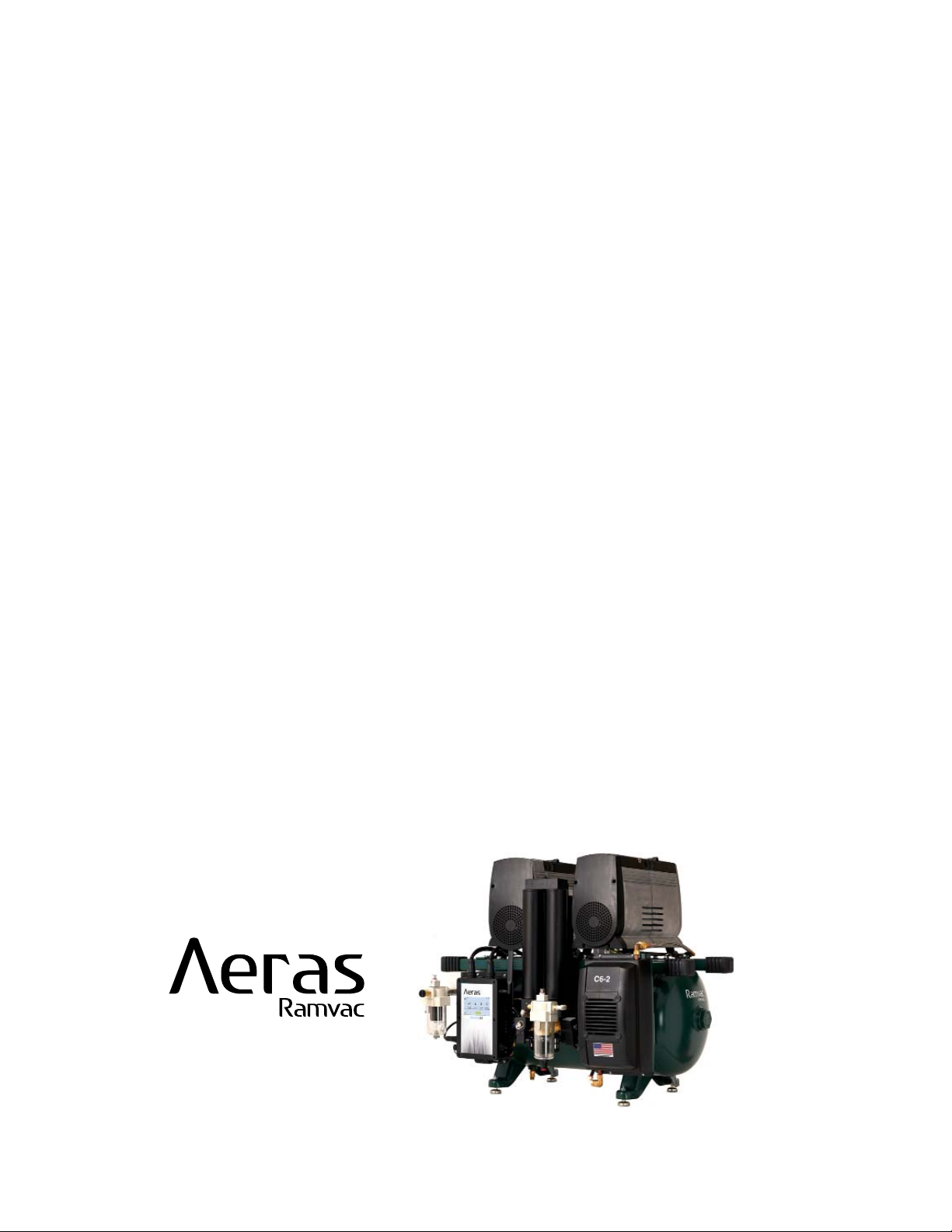
DentalEZ RAMVAC AERAS 3 User manual

COMPRESSOR
MODELS:
C3-2, C4-1, C4-2,
C6-2, C7-2 & C11-2
USER MANUAL

i
TABLE OF CONTENTS
SECTION I - INTRODUCTION
Product Overview................................................................................................................................1
Product Features................................................................................................................................. 2
Specifications...................................................................................................................................... 3
Recommended Environmental Conditions.......................................................................................... 3
Classifications..................................................................................................................................... 4
Explanation of Symbols & Signs......................................................................................................... 4
Safety Precautions.............................................................................................................................. 5
SECTION II - PREINSTALLATION
Packaging ........................................................................................................................................... 7
Placement........................................................................................................................................... 8
Site Requirements .............................................................................................................................. 9
SECTION III - INSTALLATION
Feet Kit ..............................................................................................................................................10
Filter Drain Kit ....................................................................................................................................11
Low-voltage Wiring Connections....................................................................................................... 13
Outlet Plumbing Kit........................................................................................................................... 16
SECTION IV - OPERATION
How the System Works..................................................................................................................... 18
Getting Started.................................................................................................................................. 18
Aeras Control Panel.......................................................................................................................... 19
Home Screen.................................................................................................................................... 20
Information Screen ........................................................................................................................... 22
Technical Screen .............................................................................................................................. 24
Settings Screen ................................................................................................................................ 44
SECTION V - CARE
Maintenance ..................................................................................................................................... 51
SECTION VI - USER SERVICE INFO
Service Instruction............................................................................................................................ 67
Disposal of Equipment...................................................................................................................... 67
SECTION VII - PARTS
DENTALEZ Parts Online .................................................................................................................. 68
EMC INFORMATION........................................................................................................................... 69
LIMITED WARRANTY.......................................................................................................................... 73

ii
COMPRESSOR USER MANUAL
866-DTE-INFO
dentalez.com
PN: 7717-004A
NOTES:
1
PRODUCT OVERVIEW
This manual contains installation, operation, care and user service information for the Ramvac Aeras dental
compressor. To view the latest manual, go to dentalez.com to download a digital (PDF) copy.
The Aeras compressors are designed to provide trouble-free service when installed, operated and cared for according
to the procedures set forth in this manual. They are NFPA 99C Level 3 dental compressors.
To ensure proper installation, carefully read all the instructions contained in this manual prior to installing,
operating, and servicing. For safety, pay close attention to all warnings, cautions, notices and notes.
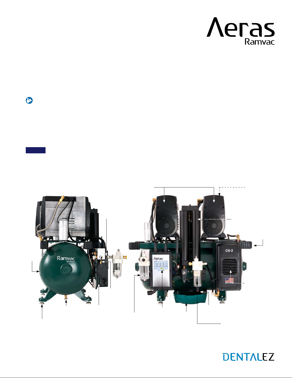
Before starting installation procedures, review the illustration to become familiar with the components of the
compressor (FIGURE 1).
After the compressor is installed, review the features, operation procedures and care guidelines with the doctor’s staff.
LEAVE THIS MANUAL IN THE DOCTOR’S OFFICE.
NOTICE
Installation by an authorized Ramvac dealer service technician is recommended.
For any questions about an order, please contact a Ramvac customer service representative at 866-DTE-INFO.
SECTION I - INTRODUCTION
FIGURE 1. MAIN COMPONENTS OF THE AERAS COMPRESSOR (SIDE AND FRONT VIEWS)
SAFETY
VALV E
FGH
CONNECTOR
COMPRESSOR
MOTOR HEADS
TOUCH
SCREEN
CONTROL
PANEL COALESCING FILTER
RUBBER
HAND
GRIPS (4)
FEET (4)
TANK
HEAT
EXCHANGER
& FAN
DUAL COLUMN
DESICCANT TOWER
INTAKE
FILTER(S)
TANK
PETCOCK
SHUT-
OFF
VALV E
PARTICULATE
FILTER
FILTER
DRAIN
BOWL
FILTER
DRAIN
2
COMPRESSOR USER MANUAL
866-DTE-INFO
dentalez.com
PN: 7717-004A
PRODUCT FEATURES
The Aeras Compressor by Ramvac offers increased productivity while decreasing downtime. The compressor is
dependable, quiet and simple to operate. In order to achieve the most efficient use in the operatory and understand
what the compressor offers, here is a compilation of some of those features and benefits.
STANDARD FEATURES
Aeras features the latest cloud-based technology that offers active monitoring with data streaming from embedded
sensors. When subscribed to smart monitoring service, potential issues are automatically detected, and diagnostic
information is relayed to the appropriate person, helping to prevent downtime. Information can be accessed via a
web browser on any device. Users also can remotely schedule the equipment to power ON and OFF.
Dual column desiccant tower provides 100% continuous supply of dry, clean air. While one column is drying, the
other is in operation. Solenoid valve activates as needed and the chambers switch processes immediately to
ensure an uninterrupted supply of air for your practice.
Design allows for easy desiccant cartridge replacement.
Stores air at -40°C, preventing growth of harmful bacteria.
Industry leading 6-year/4,200-hour (whichever comes first) warranty. All smart-enabled compressors with a
monitoring service subscription are protected with an 8-year/5,600-hour (whichever comes first) extended warranty
when additional terms are met (see LIMITED WARRANTY section of this manual).
Models available suited for 3 to 11 users.
OPTIONAL FEATURES
Optional fresh air intake kit is used when room temperatures are beyond operating temperature range and/or
when air has contaminants.
Optional sound cover lowers decibel ratings by 6 to 8 decibels. It is available for all Aeras models and is simple to
install.
SECTION I - INTRODUCTION
COMPRESSOR
3
SPECIFICATIONS
SECTION I - INTRODUCTION
AERAS 3
(C3-2)
AERAS 4
(C4-1)
AERAS 4
(C4-2)
AERAS 6
(C6-2)
AERAS 7
(C7-2)
AERAS 11
(C11-2)
Max Users 3446711
Voltage (AC) 230
(208 - 253)
115
(103 - 126)
230
(208 - 253)
230
(208 - 253)
230
(208 - 253)
230
(208 - 253)
Power Consumption
(Amps) 10.5 23 11.5 16.3 21 32
Breaker Size
(Amps) 20 30 20 20 30 40
Fusetron Size FRN 15 FRN 25 FRN 15 FRN 20 FRN 25 FRN 40
Number of Motor
Heads 122223
HP Per Motor Head 2 1.25 1.25 1.25 (Left)
2 (Right) 22
Pressure 85 PSI/586 kPa to 115 PSI/793 kPa with ± 2% Total Error Band
High-Pressure Mode*105 PSI/724 kPa to 131 PSI/903 kPa
Weight (lbs) 160 190 190 250 260 385
Dimensions
W × D × H (in) 29 × 21 × 29 29 × 21 × 29 29 × 21 × 29 35 × 25 × 30 35 × 25 × 30 41 × 29 × 32
Dimensions
(with Sound Cover) 33.3 × 29 × 34 33.3 × 29 × 34 33.3 × 29 × 34 35 × 29 × 34 35 × 29 × 34 41.1 × 33 × 36
Peak Airflow Output
@80 PSI (CFM) 6.0 6.6 6.6 9.3 12.0 18.1
Pump Up Cycle Time,
85 to 115 PSI (Sec) 45 45 45 45 40 40
Tank Size (Gal) 12 12 12 20 20 30
Filtration (microns) 0.3 Coalescing; 0.01 Final Particulate
Dryer Duty Cycle 100%
Dryer Dew Point (PDP) -40°F / -40°C
dBA Levels
(with/without
Sound Cover)
65/73 70/78 70/78 72/80 76/82 78/84
NOTES: *High-pressure mode should only be used with a compatible milling machine; not for use in general dentistry.
TRANSPORTATION AND STORAGE
Temperature range: -20°F to 165°F (-29°C to 74°C)
Relative humidity range: 0% to 95%
OPERATION
Temperature range: 35°F to 100°F (2°C to 38°C)
Relative humidity range: 0% to 95%
INDOOR USE
Altitude up to 9,000 ft (2,743 m)
RECOMMENDED ENVIRONMENTAL CONDITIONS
4
COMPRESSOR USER MANUAL
866-DTE-INFO
dentalez.com
PN: 7717-004A
CLASSIFICATIONS
Certified to:
CAN/CSA C22.2 NO. 60601-1-08
ANSI/AAMI ES60601-1:2005 (R2012)
Complies with NFPA 99C level 3 piped gas and
vacuum requirements.
Manufactured in a FDA registered
ISO 13485:2016 certified facility.
Ramvac compressors meet the most current and highest
safety standards.
Type of Protection Against Electric Shock:
Class 1 Equipment.
Degree of Protection Against Ingress of Water: IPXO.
Flammable Gases: Equipment not suitable for use in
the presence of a flammable anesthetic mixture with
air, oxygen or nitrous oxide.
Not intended for use in an oxygen rich environment.
Mode of Operation: Continuous
The authorized European representative is:
Dental Hygienics & Decontamination (DHD)
41 Blackwell Drive, Braintree Business Park
Braintree Essex, CM7 2PU, UK
Phone: +44 01787 877877 (ext. 200)
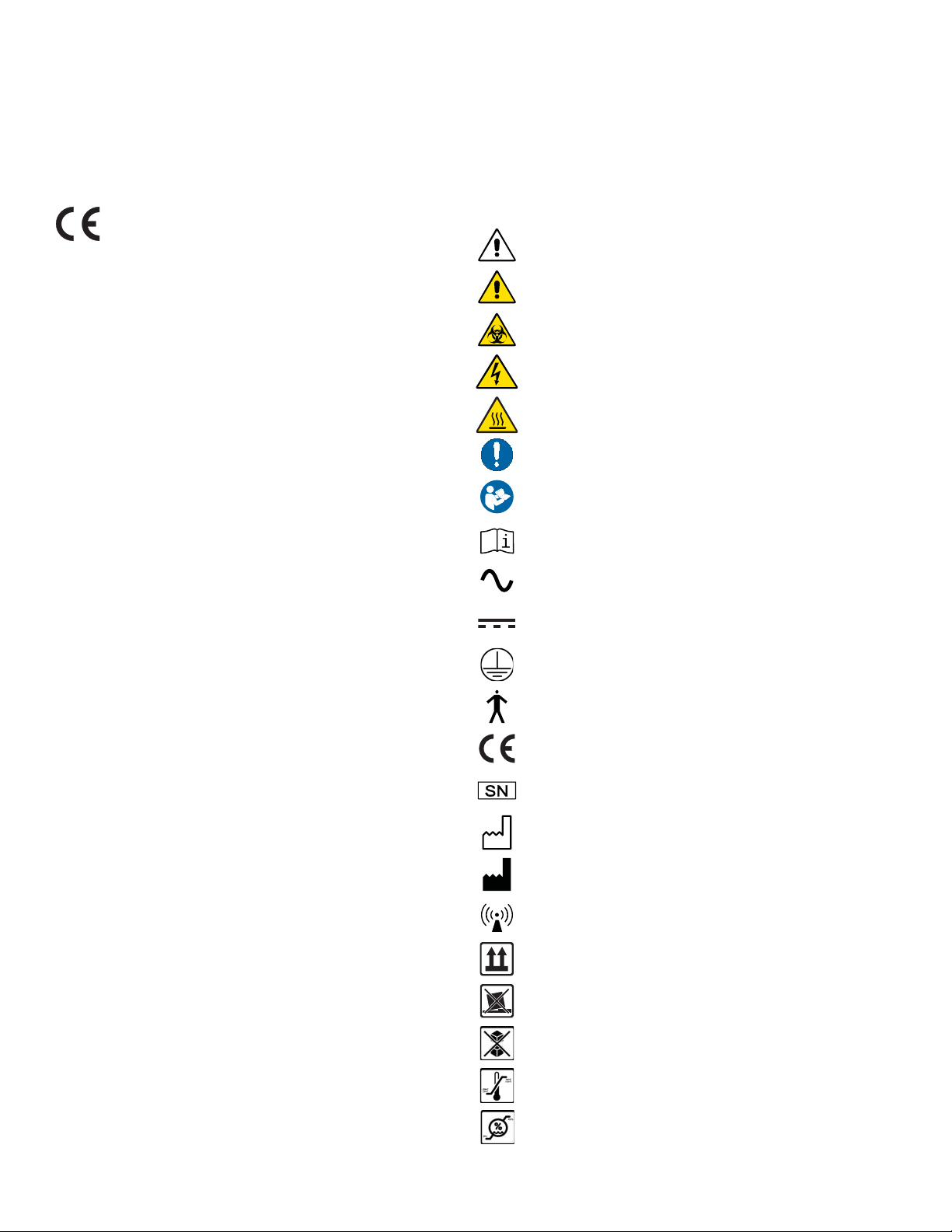
= Caution
= Warning
= Biohazard
= Warning - Dangerous Voltage
= Hot Surface
= General Mandatory Action
= Refer to Manual (Follow Instructions)
= Refer to Accompanying Documents
= Alternating Current
= Direct Current
= Protective Earth (Ground)
= Type B Applied Part
= European Certification
= Serial Number
= Manufacture Date
= Manufacturer
= Electromagnetic Radiation
= Box Must Remain Upright
= Do Not Place Box on Unlevel Surface
= Do Not Stack Box
= Box Contents Safe Temperature Range
= Box Contents Safe Humidity Range
EXPLANATION OF SYMBOLS &
SIGNS
SECTION I - INTRODUCTION

5
SAFETY PRECAUTIONS
To ensure that the safety potential of this equipment is achieved, make sure equipment is installed according to written
instructions and that the provided INSTALLATION CHECKLIST is completed. If compressor was purchased from an
authorized dealer, the dealer is responsible for providing the completed checklist.
WARNING
Do not modify this equipment without permission from Ramvac. Unauthorized modification will void the warranty
and could result in serious injury. If this equipment is modified, appropriate inspection and testing must be
conducted to ensure continued safe use of equipment.
Electrical shock could occur as a result of improper grounding. This product must be grounded according to NEC
regulations and local codes.
Portable RF communications equipment (including peripherals such as antenna cables and external antennas)
should be used no closer than 30 cm (12") to any part of the compressor, including cables specified by the
manufacturer. Otherwise, degradation of the performance of this equipment could result.
Property damage and/or personal injury may result if directions are not followed or OEM parts are not used.
Always turn off compressor and remove power from compressor when servicing. (Turn off power at disconnect or
service breaker.)
Danger of fire or explosion when using flammable substances.
Never leave children unattended when compressor is in use.
CAUTION
The compressor has several guards designed to protect against accidental contact with dangerous components.
Do not remove these guards until power has been disconnected/turned off from the equipment. If service is
required with the guard removed and the power on, it should only be performed by a qualified service technician.
Always replace any guards that have been removed for service or that may have been damaged.
During installation, always ensure all electrical, plumbing or other utilities are properly located to avoid possible
tripping or falling hazards. Always follow all local, state and national building codes, as well as any applicable
workplace safety regulations.
Use of a plug for electrical service is not recommended. Incorrect connections will cause a drop in line voltage
and/or loss of power. Overheating could result.
Connect only equipment suitable for listed maximum pressure of the compressor.
The EMISSIONS characteristics of this equipment make it suitable for use in industrial areas and hospitals
(CISPR 11 class A). If it is used in a residential environment (for which CISPR 11 class B is normally required) this
equipment might not offer adequate protection to radio-frequency communication services. The user might need to
take mitigation measures, such as relocating or re-orienting the equipment.
SECTION I - INTRODUCTION

6
COMPRESSOR USER MANUAL
866-DTE-INFO
dentalez.com
PN: 7717-004A
NOTICE
Medical electrical equipment needs special precautions regarding electromagnetic (EMC) compatibility and needs
to be installed according to EMC information. (See EMC INFORMATION provided in this manual.)
The use of accessories, transducers, and cables other than those specified, with the exception of transducers
and cables sold by the manufacturer of this device as replacement parts for internal components, may result in
increased emissions or decreased immunity of the compressor.
Portable and mobile radio frequency (RF) communications equipment can affect medical electrical equipment.
There may be an instance, in low humidity environments, that the user of the dental compressed air system may
cause the compressor to stop as a result of electrostatic discharge (ESD) energy. To remedy this issue, cycle the
ON/OFF switch on the side of the control.
An air leakage test should be conducted on the facility air system to ensure no air leaks are present. Excessive
air leakage will impact the performance and life expectancy of your compressor. See SECTION V - CARE >
MAINTENANCE >TEST FOR AIR LEAKS instructions provided in this manual.
SAFETY PRECAUTIONS (CONTINUED)
SECTION I - INTRODUCTION

7
FIGURE 2. RUBBER GRIPS (4) FOR LIFTING
COMPRESSOR
PACKAGING
WARNING
To prevent tipping during transport, securely fasten unit to shipping pallet until final destination has been reached.
TOOLS REQUIRED
7/16" Wrench
UNPACKING COMPRESSOR CARTON
1. Carefully remove the shipping carton from the pallet containing the compressor.
2. Visually inspect the entire compressor for any shipping damage.
Visually inspect the motor isolator mounts for tearing.
If shipping damage is found, immediately contact the freight carrier and supplier.
3. Using a 7/16" wrench, remove the four nuts that secure the compressor to the shipping pallet.
4. For easier handling, four rubber grips have been
installed on the frame of the compressor for lifting
(FIGURE 2).
NOTE: Lifting the compressor assembly by any other part
or location could result in damage to the compressor.
5. Verify additional parts shipped with the compressor for
use at installation:
Outlet Plumbing Kit
Coalescing Filter Drain Kit
Feet Kit
Filter Drain Kit
Doctor’s Packet
Installation Packet
Maintenance Chart and Head Service Kit
Low-voltage Wiring Connectors (Installed on Aeras Control)
NOTE: The compressor is shipped with the shut-off valve in the CLOSED position to limit exposure of the system to
humidity. OPEN the valve after installation.
SECTION II - PREINSTALLATION
RUBBER
GRIPS
RUBBER
GRIPS

8
COMPRESSOR USER MANUAL
866-DTE-INFO
dentalez.com
PN: 7717-004A
PLACEMENT
WARNING
DO NOT install on surfaces with more than a 5° incline.
CAUTION
The compressor is front heavy. When moving with
handles, be sure to hold it securely to prevent it from
tipping and possible dropping of the device, which could
result in damage to the compressor.
This device must not be stacked during transport and
storage and must be oriented right side up during
transport and storage.
The compressor unit should not be used adjacent to or stacked with other equipment. If adjacent or stacked use
is necessary, the compressor should be observed to verify normal operation in the configuration in which it will be
used.
Locate the compressor on a level hard surface capable of supporting the compressor weight. If a level surface
is not available, the compressor is equipped with height adjustable feet to level the device. Install four adjustable
rubber feet supplied to ensure unit stands firmly on the floor (see SECTION III - INSTALLATION >FEET KIT).
Floors should be wood, concrete or ceramic tile. It is highly recommended that a higher than 30% relative humidity
be established and the operator wear a ground strap before physical contact is attempted.
Compressor is for indoor use only, in a dust free, climate controlled room.
DO NOT install in a enclosed area where ambient temperature could exceed temperature specifications of below
35°F/02°C or above 100°F/38°C while the compressor is running.
Maintain minimum 12" clearance on all sides and on top of all compressors.
A source of conditioned fresh air is required for safe operation of this compressor. The air source must be located
outside of the utility room and away from potential air contaminants.
Do not locate this device or it’s air intake opening in an area that is prone to flooding or has previously flooded.
Water can damage components, reduce life expectancy of the compressor or cause serious personal injury.
TIPPING HAZARD
SECTION II - PREINSTALLATION

9
SITE REQUIREMENTS
Before the compressor can be properly installed, the following utilities must be supplied.
This device requires proper electrical grounding for safe operation. A licensed electrician should always complete the
electrical portion of the installation process.
WARNING
To avoid risk of electric shock, this equipment must only be connected to a supply mains with protective earth.
CAUTION
During the performance of any service procedures that may involve the disconnection of a ground wire, take extra
precautions to verify the ground wire has been properly re-connected. Never leave a ground wire disconnected, since
this can create a significant safety issue.
NOTICE
This air compressor has been designed to operate within the following voltage ranges; 115V systems, 103 to 126V AC;
230V systems, 208 to 253V AC. Failure to provide sufficient voltage to this device could result in damage to electrical
components and reduced service life.
ELECTRICAL
Follow NEC, NFPA 99C, and all local codes.
Compressors are shipped with a 6-foot electrical whip of the appropriate size for the compressor.
Qualified personnel must install a dedicated electrical circuit of sufficient capacity. See SECTION I -
INTRODUCTION >SPECIFICATIONS in this manual for additional electrical information.
Any means provided to isolate this device from the supply mains shall isolate all poles simultaneously.
The disconnection means and over-current protection are to be provided by the installer (qualified electrician) in
accordance with applicable local and national electric codes. This device should always be attached to a dedicated
circuit with appropriate wiring and circuit protection. If this device is being installed as a replacement, always
have a licensed electrician inspect the existing facility electrical and complete the electrical portion of the device
installation.
PLUMBING
Attach drain tubing to fitting on bottom of coalescing filter and direct it into floor drain for proper disposal of water. If
floor drain plumbing is an issue, water can be disposed into the supplied purge bowl.
Connect compressor air outlet to facility plumbing with provided supply hose (3/8" MPT × 3/8" MPT, 6 feet in
length).
Install particulate filter to the facility shut-off valve using plumbing kit connectors provided.
Install fresh air manifold and connect fresh air intake kit supplied to external air source per NFPA 99C
recommendations.
This device should always be installed with the appropriate plumbing and fresh air intake systems. If this device
is being installed as a replacement, always have a licensed plumber inspect the existing facility plumbing and
complete the plumbing portion of the device installation.
SECTION II - PREINSTALLATION

10
COMPRESSOR USER MANUAL
866-DTE-INFO
dentalez.com
PN: 7717-004A
FEET KIT
TOOLS REQUIRED
7/16" Wrench
1/2" Wrench
PARTS INCLUDED
Foot (4 Pieces)
Flanged Nut (4 Pieces)
WARNING
Prior to starting this assembly, read, understand and follow the safety information and the assembly instructions in
this user manual.
Handles for lifting the compressor assembly are provided on each end of the device. Lifting the compressor
assembly by any other part or location could result in damage to the compressor.
The weight distribution of this compressor is unbalanced to the front of the device. Exercise care when lifting to
avoid accidental tipping and possible dropping of the device, which could result in damage to the compressor or
severe injuries to the installer.
Compressor assemblies are very heavy and may require multiple people to safely lift. Prior to lifting, check the user
manual for the weight of this model. Over-exertion could result in serious injuries to the installer.
This procedure may not comply with all safety requirements of federal, state or local agencies or safety
requirements of the installer’s employer. If a conflict does exist, follow the requirements set forth by the other
organizations.
ASSEMBLY
1. Remove the four nuts (7/16" wrench) from the bolts that
secure the Aeras compressor legs to the wooden shipping
pallet. At this point, the bolts can be removed from the legs
and the compressor can be removed from the pallet. Do
not attempt to install the feet while the compressor is on the
pallet; tipping of the pallet and subsequent loss of control
may occur.
2. Lift one end of the compressor using the integrated handles
and place blocking under the end of the tank to support the
compressor. Be careful not to damage the drain valve under
the center of the tank. Never work under a compressor that
is not supported with adequate blocking (FIGURE 3).
FIGURE 3. BLOCK THE COMPRESSOR TANK
TO INSTALL FEET
FOOT (4) FLANGED NUT (4)
SECTION III - INSTALLATION
(Continued on the next page.)
11
FIGURE 4. INSTALL FLANGED NUT
FEET KIT (CONTINUED)
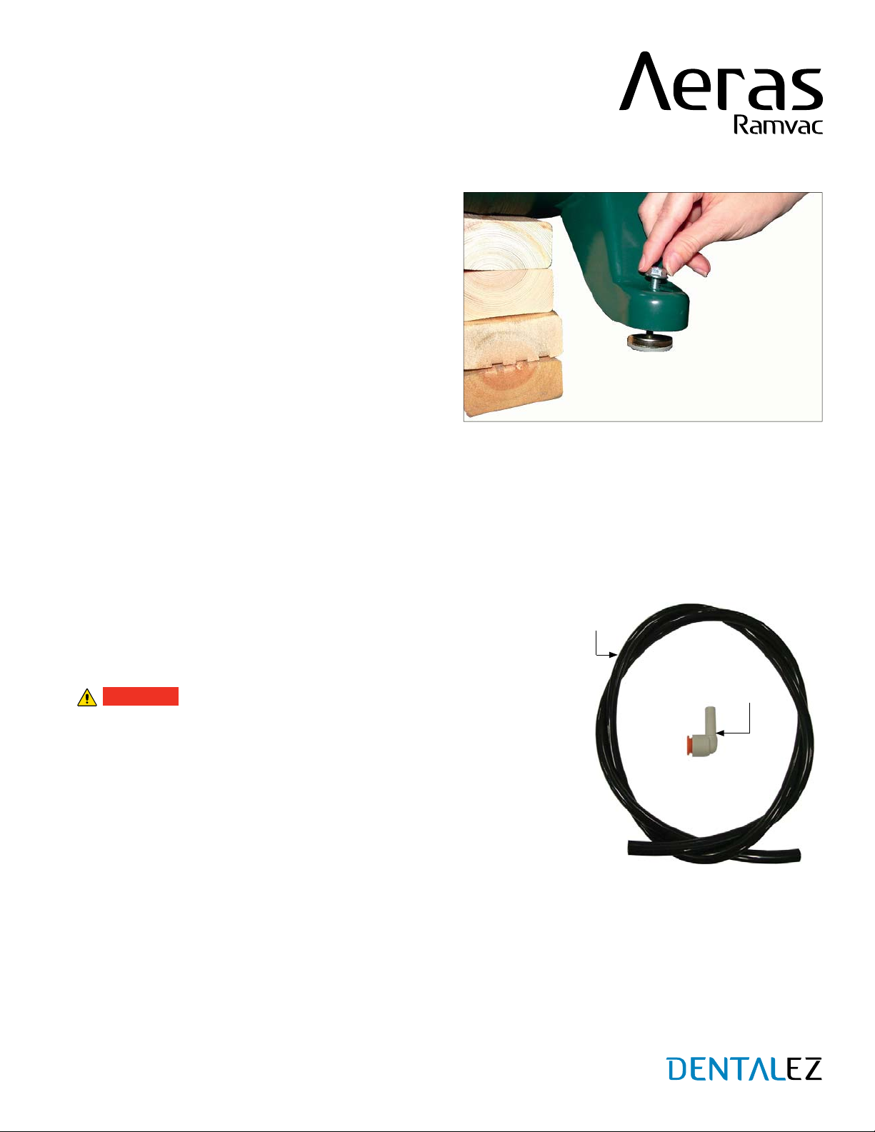
3. Thread feet into the two elevated legs from the
bottom side of the leg.
4. Adjust each foot to approximately the same height,
then thread a flanged nut (flange side toward the leg)
onto each foot (FIGURE 4).
NOTE: It is not necessary to tighten the flanged nuts at
this time.The feet will require further adjustment once
the compressor has been placed in its permanent
location in the utility room.
5. Lift the compressor and remove the blocking from
under the tank end. Repeat steps 2 through 4 for the
opposite end of the compressor.
6. After the compressor is in its permanent location in the utility room, adjust each foot using a 7/16" wrench until the
compressor is setting level. After adjusting the feet, tighten the flanged nut with a 1/2" wrench to lock the foot into
position.
FILTER DRAIN KIT
PARTS INCLUDED
Drain Hose
Elbow Fitting
WARNING
Prior to starting this assembly, read, understand and follow the safety
information and the assembly instructions in this user manual.
The bowl on the coalescing filter assembly is under high pressure while
the system is running. Allow the compressor to stop running and release
the pressure prior to removing the bowl. Failure to allow the system to
properly de-pressurize could result in severe injuries.
Always disconnect the compressor from the electrical power source
prior to conducting any maintenance or service of the equipment. The
compressor could start unexpectedly, resulting in possible injury to the service technician.
This procedure may not comply with all safety requirements of federal, state or local agencies or safety
requirements of the installer’s employer. If a conflict does exist, follow the requirements set forth by the other
organizations.
SECTION III - INSTALLATION
ELBOW
FITTING
DRAIN
HOSE
(Continued from the previous page.)
12
COMPRESSOR USER MANUAL
866-DTE-INFO
dentalez.com
PN: 7717-004A
ASSEMBLY
1. To help in determining the routing of the drain hose, read the following tips on proper installation.
The connection at the bottom of the coalescing filter is designed to work with either the elbow fitting or the 3/8"
hose provided in the kit, depending on space constraints in the utility room.
The drain hose will require a steady downward slope to the drain.
Never route the drain hose assembly across traffic areas in the utility room. This could create tripping or falling
hazards that could result in injury to personnel.
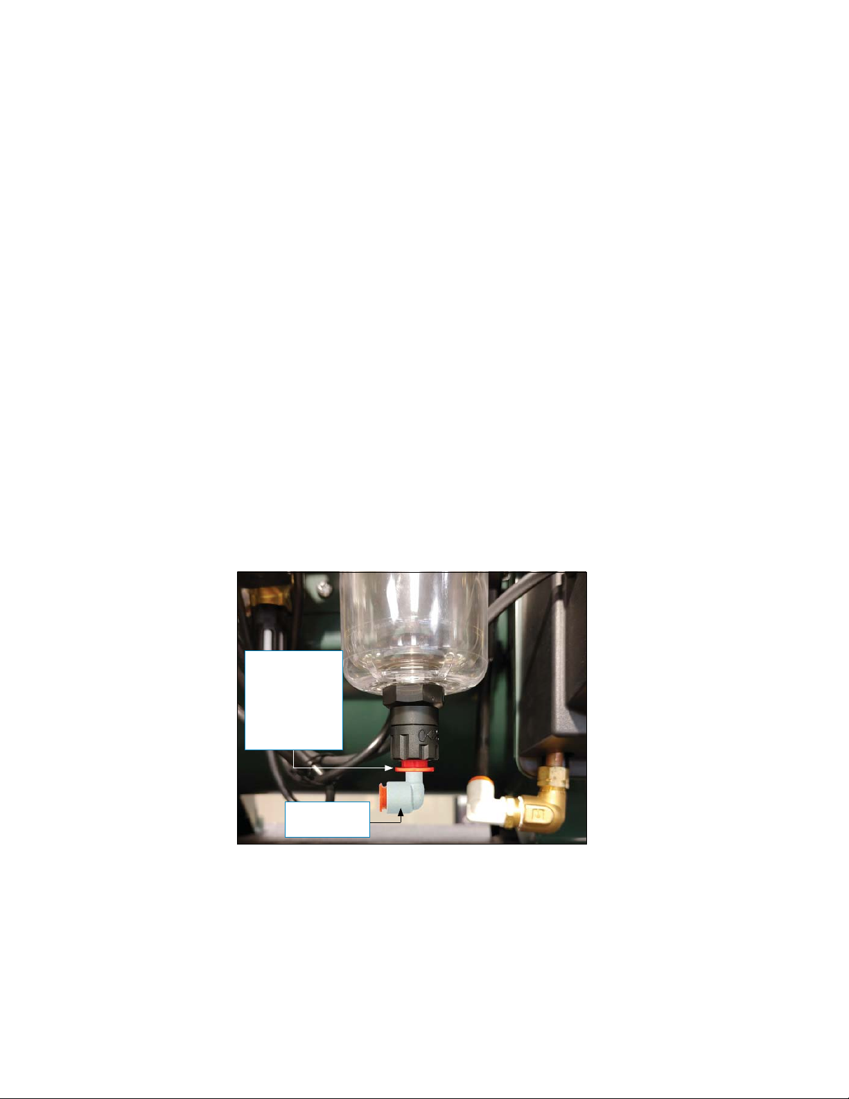
2. The connections for installing the filter drain are a “push-to-connect” style of fitting and do not require any tools to
install. After determining proper routing, simply insert either the hose end or the elbow fitting into the fitting on the
bottom of the coalescing filter bowl. Apply light force until the item stops. Gently pull the opposite direction on the
hose or fitting to determine if they have properly seated into the connection. If the fitting or hose comes out with
light force, then the hose was not fully seated into the connection and can be re-inserted again.
3. If, for some reason, the fitting or hose needs to be released from the connection, depressing the colored plastic
ring (while gently pulling on the hose or fitting) releases the hose or fitting from the connection (FIGURE 5).
NOTE: If drain plumbing is not accessible, the supplied purge bowl can be used instead to catch disposal water.The
water should be manually emptied daily.
FILTER DRAIN KIT (CONTINUED)
SECTION III - INSTALLATION
FIGURE 5. ELBOW FITTING INSTALLED IN
COALESCING FILTER DRAIN
COLORED
RING:
PUSH IN
TO RELEASE
ELBOW
FROM DRAIN
FITTING
ELBOW
FITTING

13
LOW-VOLTAGE WIRING CONNECTIONS
WARNING
Prior to starting this assembly, read, understand and follow the safety information and the assembly
instructions in this user manual.
Always disconnect the compressor from the electrical power source prior to conducting any electrical
service of the equipment. The compressor could start unexpectedly resulting in possible injury to the
service technician.
This procedure may not comply with all safety requirements of federal, state or local agencies or safety
requirements of the installer’s employer. If a conflict does exist, follow the requirements set forth by the
other organizations.
PARTS INCLUDED
Remote Switch FGH Connector - Used to control power state of this compressor from a remote location (see LOW-
VOLTAGE REMOTE SWITCHING).
Auxiliary Connector - Used to control power state of a non-Aeras vacuum, water control valve, or another non-
Aeras compressor (see LOW-VOLTAGE AUXILIARY CONNECTION).
Building Maintenance Connector - Used to connect to building maintenance system.
SECTION III - INSTALLATION
REMOTE SWITCH
FGH CONNECTOR AUXILIARY
CONNECTOR
BUILDING
MAINTENANCE
CONNECTOR
FIGURE 6. AERAS CONTROL PANEL LOW-VOLTAGE WIRING CONNECTIONS
FRONT VIEW
BUILDING
MAINTENANCE
CONNECTOR
AUXILIARY
CONNECTOR
REMOTE SWITCH
FGH CONNECTOR
SIDE VIEW
CONTROL PANEL CONNECTOR LOCATIONS

14
COMPRESSOR USER MANUAL
866-DTE-INFO
dentalez.com
PN: 7717-004A
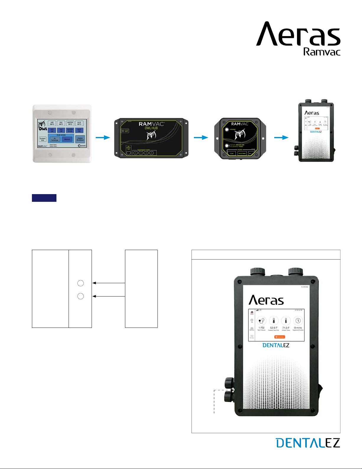
NON-ILLUMINATED REMOTE SWITCHES
Non-illuminated switches provide no
indication for system status.
ILLUMINATED REMOTE PANELS
Switch light is steady on when system is running normally.
Switch light flashes for maintenance or one of the heads has
been disabled by the disable button on the control panel.
Recommended Switching
Alternative Switching
Toggle Switch
or Other Non-
Illuminated
Switch
(Option)
Aeras
Control
Terminals
F
H
Air Switch +24V DC
+24V DC
DC Common
F
G
H
Air Light
Common
Ramvac
Remote
Panel (or
Equivalent)
with
Illuminated
24V DC
Switch
Aeras
Control
Terminals
F
H
G
1
2
3
AIR
LOW-VOLTAGE REMOTE SWITCHING
NOTICE Maximum wire length for 18-gauge wire is 500 feet.
Low-voltage remote switching is used to turn the system on and off from a remote location.Your Aeras compressor is
manufactured to continuously cycle as required throughout the workday. Power the compressor off at end of day.
LOW-VOLTAGE WIRING CONNECTIONS (CONTINUED)
SECTION III - INSTALLATION
AERAS CONTROL PANEL
REMOTE
SWITCH
FGH
CONNECTOR
(Continued on the next page.)
15
SECTION III - INSTALLATION
LOW-VOLTAGE WIRING CONNECTIONS (CONTINUED)
LOW-VOLTAGE AUXILIARY CONNECTION
NOTICE Maximum wire length for 18-gauge wire is 500 feet.
Low-voltage auxiliary connection is used to connect a non-Aeras vacuum, master water control valve, or another
non-Aeras compressor to this Aeras compressor. The auxiliary power state will match the power state of this Aeras
compressor (ON/STANDBY).
Auxiliary Wiring
Aeras
Control
Terminals
S2 Control
Terminals
or
C2 Control
Terminals
or
Water
Control Valve
Terminals
F
H
AUXILIARY
CONNECTOR
AERAS CONTROL PANEL
Switch
Common
Alternative Switching
(Continued from the previous page.)
OWL Touch OWL Hub OWL Interface Aeras Control Panel
16
COMPRESSOR USER MANUAL
866-DTE-INFO
dentalez.com
PN: 7717-004A
OUTLET PLUMBING KIT
WARNING
Prior to starting this assembly, read, understand and follow the safety information and the assembly instructions in
this user manual.
Never route the facility supply hose across traffic areas in the utility room. This could create tripping or falling
hazards that could result in injury to personnel.
The compressor system may be pressurized; follow the discharge procedures in the user manual prior to
conducting any repairs or maintenance. Working on pressurized components could result in severe injuries or
even death. It is recommended any repairs or service be performed by a qualified service technician.
When installing air lines in a new facility, always follow NFPA 99 standards (or local codes) and maintain
cleanliness throughout.
Prior to or during the replacement of compressors, always verify the cleanliness of the existing air lines in the
facility. Old or malfunctioning compressors can cause unhealthy deposits of mold, dust or dirt.
This compressor is designed for dental procedures and powering dental equipment and can be safely used in the
oral cavity for such purposes. Under no circumstances should it be supplied or considered as medical/breathing
air for a patient.
Installation of this device should be conducted by licensed electrical and plumbing contractors and should
always follow the instructions found in the various manuals, unless local state or national building codes specify
otherwise. Failure to comply with all applicable codes and installation procedures may result in personal injury,
damaged components or reduced life expectancy of this product.
Never direct the air stream toward any portion of the body or others in the vicinity. Pressurized air streams can be
extremely hazardous to your health and can result in death in certain circumstances.
This procedure may not comply with all safety requirements of federal, state or local agencies or safety
requirements of the installer’s employer. If a conflict does exist, follow the requirements set forth by the other
organizations.
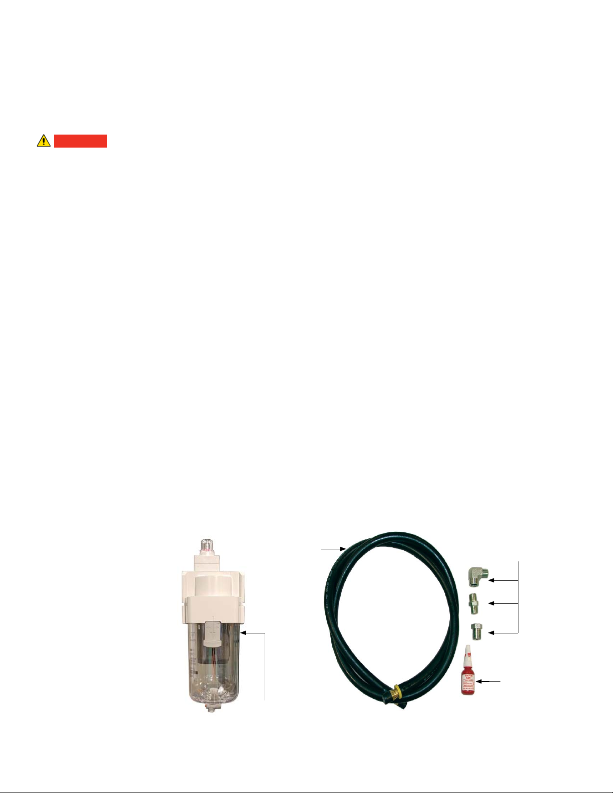
PARTS INCLUDED
Final Filter (Particulate)
Facility Supply Hose
Fittings
Thread Sealer
FITTINGS
THREAD
SEALER
FACILITY
SUPPLY
HOSE
SECTION III - INSTALLATION
FINAL FILTER
(PARTICULATE)

17
ASSEMBLY
1. Determine the best routing for the facility supply hose and the filter assembly. The filter can be mounted in two different
directions, depending on the safest and easiest route for the hose (FIGURE 7).
Always use the hose assembly provided to connect the compressor to the facility airlines. If a longer hose is required,
be certain the product used is rated to an adequate pressure level and is intended for compressed air systems.
2. Utilize the fittings provided to mount the filter assembly in the orientation determined in step 1. A small tube of thread
sealer has been provided in the kit. Do not over-apply the thread sealer; just a couple of drops on the male threads of all
the fittings will provide an adequate seal. Tighten fittings as needed.
3. Thread the final filter onto the fittings and tighten it into the desired position (FIGURE 7).
NOTE: The final filter has to be installed in the correct flow orientation.
4. Thread the facility supply hose into the final filter and tighten. Both ends of the hose have swivel fittings to make
installation easier.
5. Attach the other end of the hose to the facility piping. The kit contains an adapter bushing to adapt the 3/8 pipe thread
on the end of the hose to a 1/2 pipe thread on the facility piping if it is required.
6. Upon completion of the air compressor installation, always check to ensure the shut-off valve on the pressure manifold
is in the open position.
7. After the system has been pressurized, perform the following checks: (SECTION V - CARE - MAINTENANCE - TEST
FOR AIR LEAKS)
Check each joint for leaks using a soap and water mixture. Tighten any joints that may be leaking.
Check the facility plumbing for leaks, either by inspection or by completing a pressure decay test. Repair any
leaks in the facility plumbing.
OUTLET PLUMBING KIT (CONTINUED)
SECTION III - INSTALLATION
FIGURE 7. FILTER MOUNTING OPTIONS
FLOW
ARROW
FLOW
ARROW
SHUT-
OFF
VALV E
SHUT-
OFF
VALV E
This manual suits for next models
15
Table of contents
Other DentalEZ Air Compressor manuals

Popular Air Compressor manuals by other brands


Ingersoll-Rand
Ingersoll-Rand 4IRJ7N Technician guide

BOCK
BOCK HG66e/1340-4 Assembly instructions

Gardner Denver
Gardner Denver VST225 Installation, operating and service manual

Fubag
Fubag HANDY AIR SP 200 Instructions for use manual

Johnson Controls
Johnson Controls Frick QUANTUM LX Setup

EUROPE PROJECTION
EUROPE PROJECTION Jetmix 100-70 user manual