Eaton Compressor Polar Air PRS0050001 User manual

Polar Compressor Rotary Screw Compressors
Revision July.2015 www.eatoncompressor .com 877.283.7614
1 | P a g e
Operating Instructions
ROTARY SCREW
COMPRESSORS
Polar Air designs and manufactures products for safe operation.
However, operators and maintenance persons are responsible for
maintaining safety. All safety precautions are included to provide
a guideline for minimizing the possibility of accidents and property
damage while equipment is in operation. Keep these instructions
for reference.

Polar Compressor Rotary Screw Compressors
Revision July.2015 www.eatoncompressor .com 877.283.7614
2 | P a g e
Contents Page No
Variable Speed Drive Information..............1
Model Specification Charts.....................2-3
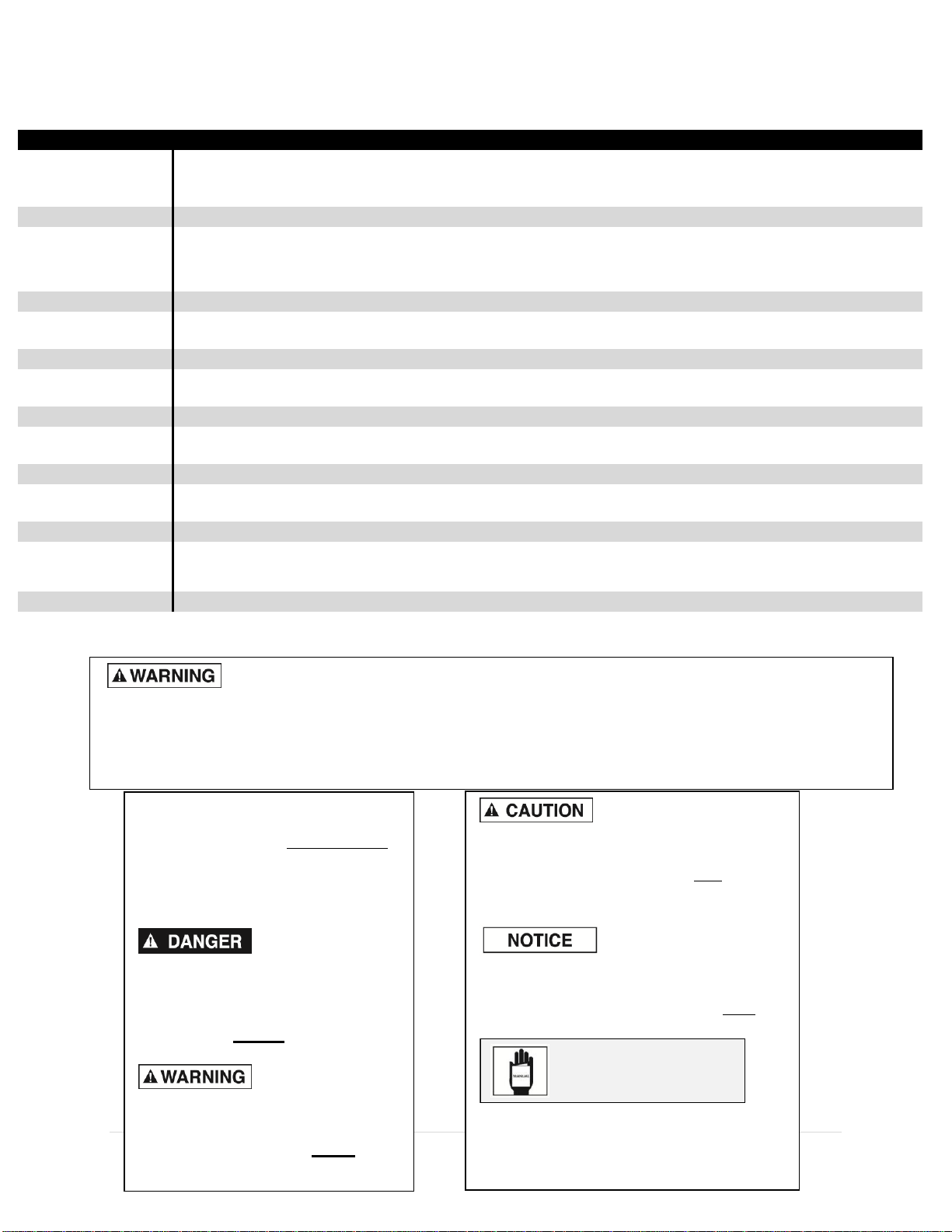
Safety Information ......................................4
Tag Definitions........................................4
Basic Guidelines .....................................4
Breathable Air .........................................4
Pressurized Components........................4
Personal Protective Equipment...............4
Inspection....................................................5
Forklift Safety..........................................5
Lifting Safety...........................................5
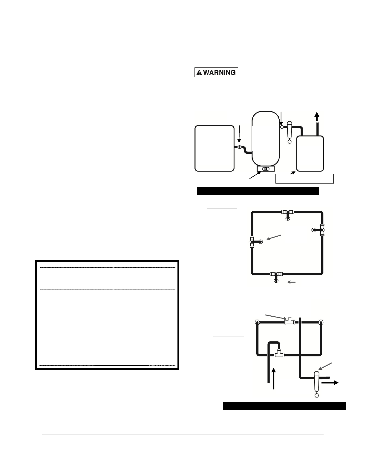
Installation...................................................6
Area........................................................6
Piping......................................................6
Safety Steps............................................6
Installing..................................................6
Oil Check .............................................7-8
Electrical Installation................................8
Motor Rotation.........................................9
System Description.....................................9
Air Process..............................................9
Lubrication Process.................................9
System Components ..................................9
PLC (Programmable Logistical Control) ..9
Setting:oC/oF; BAR/PSI; Lang; Time/Date.10
Working Pressures................................11
Clock Timer Settings.............................11
Working Timer –Unloading Delay.........12
Maintenance Notifications .....................13
Resetting Maintenance Alarms.........13-15
Mechanical Components..................16-19
Resetting Overload Protection...............16
Operation...................................................19
Safety Rules.....................................19-20
Initial Checks.........................................20
Start-Up.................................................21
Power Outages .....................................21
Storage .................................................21
Restarting Procedure.............................21
Maintenance ..............................................21
Safety Steps.................................... 21-22
Lubricating Oil .......................................22
Belts……………………………………22
Changing Oil..........................................22
Oil Capacities........................................22 23
System Pressure...................................23
Safety Valve..........................................23
Air/Oil Separator Filter...........................23
OPTIONAL: Cabinet Intake Filter(s) ......23
Maintenance Schedule..............................24
Troubleshooting.................................. 25-29
Wiring Diagrams........................................29
Warranty ....................................................34
Variable Speed Drive
The variable speed drive is an auxiliary feature
available on all Polar Air compressors. A variable
speed drive or VSD regulates amp draw during start-
up and motor speed during operation according to air
demand.
All Polar Air compressors are equipped with a VSD
compliant motor, ventilated electrical box &
adequate space in compressor cabinet for easy
installation. The electronic controller (PLC) for the
compressor unit provides start/stop command and
display fault status for the VSD device.
Be sure to install VSD in a clean,
dust-free environment.
To convert to Variable speed drive, contact
Polar Air customer service for more
information, 1-877-283-7614
VSD Device
Dedicated Cooling Fan
Wiring Access Area
Each compressor cabinet has built-in VSD compartment

Polar Compressor Rotary Screw Compressors
Revision July.2015 www.eatoncompressor .com 877.283.7614
3 | P a g e
Polar Air Rotary Screw Systems: 25 Hp - 60 Hp (VSD Compliant)
Model No. PRS0250003
Description
Motor 25HP 40HP
208V:77 208V:124
Amp Draw SF 230V: 70 230V:112
460V: 35 460V:56
RPM 1750
Voltage 208/230/460/575 208/230/460/575 208/230/460/575
SCFM @ 100 PSI 108 129
Start Type Y-Delta & VSD
Drive Type Belt
Air End Model B101/EVO6
Noise DB(a) 73 75
Outlet Size NPT 1"
Oil Capacity 2.5 GAL
Dimensions L.W.H
(inches)
43X48X62
Weight (lbs.) 1374
NPT 1-1/4"
5.5 GAL
54X51X65
2052
NPT 1-1/4"
5.5 GAL
54X51X65
2220
261
Y-Delta & VSD
Belt
EUDUR012/EV09
81
54X51X65
2052
60HP
230V:161
460V:81
1750
208/230/460/575
50HP
1750
235
Y-Delta & VSD
Belt
EUDUR012/EV09
79
Belt
EUDUR012/EV09
79
NPT 1-1/4"
5.5 GAL
1750
188
Y-Delta & VSD
Dual Voltage
Dual Voltage
30HP
230V:83
208V:91
NPT 1"
2.5 GAL
43X48X62
1370
Y-Delta & VSD
Belt
B101/EVO6
208/230/460/575
PRS0300003
Three Phase
PRS0400003
Three Phase
Three Phase
PRS0600003
PRS0500003
Three Phase
Dual Voltage
Three Phase
Dual Voltage
Dual Voltage
460V:41
208V:152
230V: 138
460V: 69
208V:178
1750
Model No. PRS0050001 PRS0070001 PRS0100001 PRS0070003 PRS0100003 PRS0150003 PRS0200003
Description Single Phase Single Phase Single Phase Three Phase Three Phase Three Phase Three Phase
Dual Voltage Dual Voltage Dual Voltage Dual Voltage Dual Voltage
Motor 5 H.P 7.5HP 10HP 7.5HP 10HP 15HP 20HP
Amp Draw SF 24 32 40 230V: 22 230V: 30 230V: 42 230V: 57
460V: 11 460V: 15 460V: 21 460V: 29
RPM 2810 1750 1750 1750 1750 1750 1750
Voltage 208/230 208/230 208/230 208/230/460/575 208/230/460/575 208/230/460/575 208/230/460/575
SCFM @ 100 PSI 21 29 45 29 45 62 85
Start Type Magnetic Starter Magnetic Starter Magnetic Starter Y-Delta & VSD Y-Delta & VSD Y-Delta & VSD Y-Delta & VSD
Drive Type Belt Belt Belt Belt Belt Belt Belt
Air End Model B40/EVO2 B40/EVO2 B40/EVO2 B40/EVO2 B40/EVO2 B60/EVO3 B60/EVO3
Noise DB(a) 60 62 64 62 64 67 85
Outlet Size NPT 3/4" NPT 3/4" NPT 3/4" NPT 3/4" NPT 3/4" NPT 1" NPT 1"
Oil Capacity 1.3 Gal 1.3 gal 1.3 Gal 1.3 Gal 1.3 Gal 1.5 Gal 1.5 Gal
Dimensions L.W.H
(inches)
43x48x43 43x48x43 48x45x48 43x48x43 48x45x48 48x45x50 48x45x50
Weight (lbs.) 451 542 630 542 630 788 880
Polar Air Rotary Screw Systems: 5 Hp - 20 Hp (VSD Compliant)

Polar Compressor Rotary Screw Compressors
Revision July.2015 www.eatoncompressor .com 877.283.7614
4 | P a g e
Polar Air Rotary Screw Systems: 75 Hp - 200 Hp (VSD Compliant)
Model No. PRS0750003 PRS1000003 PRS1250003 PRS1500003 PRS1750003 PRS2000003
Description Three Phase Three Phase Three Phase Three Phase
Dual Voltage Dual Voltage Dual Voltage Dual Voltage Dual Voltage
Motor 75HP 100HP 125HP 150HP 175HP 200HP
Amp Draw SF 460V: 256
RPM 1750 1750 1750 1750 1750 1750
Voltage 208/230/460 208/230/460 208/230/460 460 460 460
SCFM @ 100 PSI 353 424 570 706 812 883
Start Type Y-Delta & VSD Y-Delta & VSD Y-Delta & VSD Y-Delta & VSD Y-Delta & VSD Y-Delta & VSD
Drive Type Direct Drive Direct Drive Direct Drive Direct Drive Direct Drive Direct Drive
Air End Model E25G E25G E75G E75G E75G E75G
Noise DB(a) 78 80 83 83 87 87
Outlet Size NPT 2" NPT 2" NPT 3" NPT 3" NPT 3-1/2" NPT 3-1/2"
Oil Capacity 8 gal 8 gal. 18 18 24 24
Dimensions L.W.H
(inches)
83x52x72 86x56x73 102X63X75 102X63X75 68X105X78 68"x105"x78"
Weight (lbs.) 3606 3606 5800 5800 6538 6538
460V: 221
208V:361
230V: 327
460V: 163
460V: 188
Three Phase
Three Phase
Dual Voltage
230V:196
460V: 98
208V:216
208V:290
230V:262
460V:131
Before installing your compressor it is imperative due to varying local wiring codes to consult a
professional licensed electrician. Installation of electrical wire can be extremely hazardous, if done improperly,
it can result in personal injury or property damage. Eaton Compressor is not responsible for any damages
incurred due to improper installation of any electrical lines or components.
Safety
This manual contains very important
information on SAFETY and how to
PREVENT EQUIPMENT
PROBLEMS. The following will help
in understanding this information:
DANGER
INDICATES AN
IMMINENTLY HAZARDOUS
SITUATION WHICH, IF NOT
AVOIDED, WILL RESULT IN
DEATH OR SERIOUS INJURY.
WARNING
indicates a
potentially hazardous situation
which, if not avoided, could
result in death or serious injury.
CAUTION indicates a potentially hazardous
situation, which if not avoided, may result in
minor or moderate injury.
NOTICE indicates important
information that if not followed, may
cause damage to equipment.
Read all manuals included with this
product carefully. Be thoroughly
familiar with the controls and the
proper use of the equipment.

Polar Compressor Rotary Screw Compressors
Revision July.2015 www.eatoncompressor .com 877.283.7614
5 | P a g e
Basic Guidelines:
CALIFORNIA PROPOSITION 65
This product or its power
cord may contain chemicals know to the
State of California to cause cancer and
birth defects or other reproductive harm.
Wash hands after handling.
1. Allow only trained, authorized
persons who have read and
understood these operating
instructions to use this compressor.
Failure to follow the instructions,
procedures and safety precautions in
this manual can result in accidents
and injuries.
2. NEVER start or operate the
compressor under unsafe conditions.
Tag the compressor, disconnect and
lock-out all power to it to prevent
accidental start-up until the condition
is corrected.
3. Install, use and operate the
compressor only in full compliance
with all pertinent OSHA regulations
and all applicable Federal, State &
Local codes, standards and
regulations.
4. NEVER modify the compressor
and/or controls in any way.
5. Keep a first aid kit in a convenient
place. Seek medical assistance
promptly in case of injury. Avoid
infection by caring for any small cuts
and burns promptly.
Breathable Air
1. NEVER use air from this compressor
for breathable air except in full
compliance with OSHA Standards
29 CFR 1910 and any other Federal,
State or Local codes or regulations.
DEATH OR SERIOUS
INJURY CAN RESULT
FROM INHALING
COMPRESSED AIR
WITHOUT USING
PROPER SAFETY
EQUIPMENT. SEE OSHA
STANDARDS ON SAFETY
EQUIPMENT.
2. DO NOT use air line anti-icer
systems in air lines supplying
respirators or other equipment used
to produce breathable air. DO NOT
discharge air from these systems in
unventilated or other confined areas.
Pressurized Components
This equipment is supplied with a
pressure vessel protected by a relief
valve. DO NOT attempt to open valve
while the machine is under pressure.
Personal Protective Equipment
Be sure all operators and others around
the compressor and its controls comply
with all applicable OSHA, Federal, State
and Local regulations, codes and
standards relating to personal protective
equipment. This includes respiratory
protective equipment, protection to the
extremities, protective clothing,
protective shields and barriers, electrical
protective equipment, and personal
hearing equipment.

Polar Compressor Rotary Screw Compressors
Revision July.2015 www.eatoncompressor .com 877.283.7614
6 | P a g e
Inspection
Prior to using the compressor, check for external
damage that might have occurred during transit.
Make sure pallet-
mounted compressors are firmly secured
to the pallet before moving. NEVER
attempt to move a compressor that is not
secure or serious injury or property
damage could result.
A forklift may be necessary for unloading the
Polar Air compressor, and requires a certified
forklift operator, using all forklift safety
measures. Refer to figure 1 for safe unloading
procedures.
Forklift Safety
1. Be sure load is secure and well balanced
before moving compressor.
2. Make sure forks are fully engaged and
tipped back before lifting or moving
compressor.
3. Keep load as low as possible and
observe safe operating practices.
Lifting Safety
1. Carefully inspect all lifting equipment
and make sure it is in good condition.
Rated capacity should exceed
compressor weight; the lifting hook has
a functional safety latch or equivalent
and is properly attached to lifting
feature.
2. Make sure lifting points are in good
condition and tighten any loose nuts or
bolts before lifting.
3. Use provided lifting feature or
appropriate sling. A sling must be used
when moving compressor with a
helicopter or other air-borne equipment.
Be sure to follow OSHA standards 29
CFR 1910 Subpart N.
4. Use guide ropes or equivalent to prevent
twisting or swinging of the compressor
while it is in the air and NEVER attempt
to lift in high winds. Keep compressor
as low to the ground as possible.
5. Keep persons away and make sure no
one is under the compressor while it is
lifted.
6. Only use lifting features provided for
entire compressor package, NEVER use
bolts or other hooks on individual
components to move the compressor.
7. Put compressor on level surface that can
support the weight of the compressor
and loading equipment.
Do not operate unit if
damaged during shipping, handling or
use. Bursting may result, causing injury
or property damage.
Remove shipping brackets
from each corner of mounting base before
operating compressor. Refer to Figure 2.
Figure 1: Use Lumber to Protect Compressor
Lumber
Main Frame
Compressor Enclosure
Shipping Bracket
(remove 2)
Figure 2: Remove Shipping Brackets

Polar Compressor Rotary Screw Compressors
Revision July.2015 www.eatoncompressor .com 877.283.7614
7 | P a g e
Installation
Area
Exhaust air from this unit can be used to
supplement environment heat. Install unit in
separate room then create duct system as
shown in figure 3.
1. Install compressor in a clean, well
ventilated and well lit area. Make
sure air inlet is away from exhaust
fumes or other toxic, noxious or
corrosive fumes or substances.
Installation area must maintain low
relative humidity and a temperature
range between 35o–110o F (2o–43
oC). This unit must be kept under
roof and away from rain, snow,
etc.
In environments where
fine dust is common, such as granite or
concrete plants, the compressor MUST be
installed in a separate area with dedicated
ventilation. Failure to provide dust free
operating area voids the warranty.
For
Cold
Weather Use:
Open shop vent and close outside
vent to use exhaust heat from compressor.
For
Warm
Weather Operation:
Close shop vent and open outside
vent to divert exhaust heat outdoors. c
i
d
2. Clearances around compressor. At
least:
36 inches sides and back
3 feet in front of compressor.
This compressor unit is
equipped with internal rubber vibration
isolators. To avoid internal pump damage,
DO NOT use an additional rubber mounting
surface when installing compressor.
3. Make sure compressor base is on a
hard, flat surface and anchored
securely.
4. If installation is above the first story
of a building, use appropriate
vibration insulation.
Tank Sizing Guideline:
Tank capacity must be at least 1.2 gallons
(5.3 L.) for every CFM of air produced by
compressor. This eliminates wear on
internal pump parts.
Vent to Shop
(Open/Close)
Vent to Outside
(Open/Close)
Rotary Screw
Compressor
Cabinet
Fresh Air
Inlet
(Keep
Open)
Figure 3: Utilize Exhaust Heat

Polar Compressor Rotary Screw Compressors
Revision July.2015 www.eatoncompressor .com 877.283.7614
8 | P a g e
Piping
Safety Steps
1. Install appropriate flow-limiting
valves as necessary, according to
pipe size(s) and run lengths. This
reduces pressure in case of hose
failure, per OSHA Standard 29 CFR
1926.302(b)(7).
2. Flow-limiting valves are listed by
pipe size and rated CFM. Select
appropriate valves accordingly, in
accordance with the manufacturer’s
recommendations.
3. Do not install check valve as
compressor has internal check valve.
Installing
1. Install piping as shown in Figure 4.
Refer to Figure 5 for recommended,
closed loop installation.
2. Make sure any tube, pipe or hose
connected to the unit can withstand
operating temperatures and retain
pressure.
Minimum Pipe Size For Compressed
Air Lines
Pipe Size Shown in inches)
Length Of Piping System
SCFM
25 ft.
50 ft.
100
ft.
250
ft.
20
3/4
3/4
3/4
1
40
3/4
1
1
1
60
3/4
1
1
1
100
1
1
1
1-1/4
125
1-1/4
1-1/4
1-1/2
1-1/2
150
1-1/2
2
2
2
200
2
2
2
2
Never use plastic (PVC) pipe
for compressed air. Serious injury or death
could result.
Rotary
Screw
Compressor
Cabinet
Air
Storage
Tank
Air
Dryer
To Shop
Piping
Ball
Valve
Water Drain Valve
Ball
Valve
Figure 4: Basic Piping Diagram
PLAN VIEW
Closed loop
system
Install tee fitting
in piping from air
supply to minimize
pressure drop and
to allow airflow in
two directions.
Air Drop
(typ.)
Air Drop
Install tee fitting with branch to top to
minimize condensation in air drop
ELEVATION
From
Compressor
To Air Tool
Water trap
w/drain
Figure 5: Closed Loop Installation
From Compressor
Auto Drain on back side

Polar Compressor Rotary Screw Compressors
Revision July.2015 www.eatoncompressor .com 877.283.7614
9 | P a g e
1. Install appropriate ASME code
safety valves and adequate
condensate drains on piping
system.
2. Never use reducers in discharge
piping. Keep all piping and fittings
the same size in the piping system to
help prevent pressure drops.
3. For permanent installations of
compressed air systems, determine
total length of system and select
correct pipe size. Bury underground
lines below frost line and avoid areas
where condensation could build-up
and freeze.
4. Test entire piping system before
underground lines are buried, and
find and repair all leaks before using
compressor.
Oil Capacities:
7.5–10 HP –1.3 Gallon
15 –20 HP –1.5 Gallon
25 –30 HP –2.5 Gallon
40 –60 HP –5.5 Gallon
75 –100 HP –8 Gallon
125 –150 HP –18 Gallon
175 –200 HP –24 Gallon
DO NOT OVERFILL.
Residual oil may still be in the compressor.
The above capacities can be used for
guidelines, but use the upper arrow fill line
on the sight glass (See page 7). Over filling
causes oil to blowout the inlet valve and
through the air filter, also oil could push
past the separation system resulting in oil in
the air lines.
Oil Check
This unit is shipped with oil in it and ready
to operate. Check for proper oil level before
operating the compressor. Compressor must
be off at least 45 min. - 1 hr. before
checking to ensure accurate reading. Refer
to figure 6.
Use only Polar Air oil,
model no. Oil003. For food
manufacturing applications, use model no.
Oil001. Use of any other product will cause
product damage and void the warranty.
Refer to warranty statement for oil
requirements.
Labels on
tank show
proper oil
levels. Oil
should be
near bottom
of sight
tube when
running.
Figure 6: Sight Tube for Lubricating Oil

Polar Compressor Rotary Screw Compressors
Revision July.2015 www.eatoncompressor .com 877.283.7614
10 | P a g e
Electrical Installation
TO PREVENT DEATH
OR SERIOUS INJURY,
ONLY TRAINED AND
AUTHORIZED
PERSONNEL SHOULD
INSTALL AND MAINTAIN THIS
COMPRESSOR IN ACCORDANCE
WITH ALL APPLICABLE FEDERAL,
STATE AND LOCAL CODES,
STANDARDS AND REGULATIONS.
FOLLOW ALL NEC (National Electric
Code) STANDARDS ESPECIALLY
THOSE CONCERNING EQUIPMENT
GROUNDING CONDUCTORS.
1. Follow all NEC and local codes for
electrical wiring. Allow only authorized
Polar Air service person or certified
electrician to install electrical
components.
2. Put unit on dedicated circuit and make
sure
no other electrical equipment is wired
into
it. Failure to wire unit on independent
circuit can cause circuit overload and/or
imbalance in motor phasing. Install
proper No Fuse Breaker (NFB)
according to kW output of compressor.
3. Ensure incoming service has adequate
ampere rating.
4. Ensure supply line has the same
electrical
Characteristics (voltage, cycles and
phase) as the machine.Wiring for
Variable Speed Drive or typical Wye-
Delta Start. See page 1 for advantages
of VSD.
IMPROPERLY GROUNDED
ELECTRICAL COMPONENTS ARE
SHOCK HAZARDS. MAKE SURE ALL
THE COMPONENTS ARE PROPERLY
GROUNDED TO PREVENT DEATH
OR SERIOUS INJURY
1. Refer to amp load information on
motor tag and use correctly sized
wiring. Be sure to consider distance
between power supply and
machine.
2. Install surge protection device
between power supply and
compressor electrical cabinet.
3. Make sure to install properly sized
breakers and fuses.
4. The unit must be properly grounded.
DO NOT connect ground wire to air
or cooling lines. Connect ground
wire to grounding lug in the
compressor electrical cabinet.
5. Refer to amp load information on
motor tag and use correctly sized
wiring. Be sure to consider distance
between power supply and
machine.
6. Install surge protection device
between power supply and
compressor electrical cabinet.
7. Make sure to install properly sized
breakers and fuses.
8. The unit must be properly grounded.
DO NOT connect ground wire to air
or cooling lines. Connect ground
wire to grounding lug in the
compressor electrical cabinet.
Motor Rotation
After electrical installation is complete
by a certified electrician, check
the direction of the motor rotation.
To check the Rotation Lightly push
START and STOP buttons on the
instrument panel. View unit while facing
the drive pulleys (from the back). Check
directional arrows on air end of pump

Polar Compressor Rotary Screw Compressors
Revision July.2015 www.eatoncompressor .com 877.283.7614
11 | P a g e
System Description
The Polar Air compressor is highly efficient
and provides reliable performance with low
wear parts, low vibration and quiet
operation. An electric motor, which is
controlled by a Programmable Logistical
Controller (PLC), runs the compressor and
is actuated with a belt drive system. The belt
drive system utilizes pulleys to
Connect the motor to the main rotor shaft, or
a direct-drive coupling system.
Air Process
Air enters the system through the suction
valve which has an air/suction filter to
remove dust. The air is mixed with the
lubricating oil and flows into the air/oil
separator tank. It passes through an air/oil
separator filter then through a minimum
pressure check valve. Air then passes
through an air cooled after cooler then into
storage tank.
Lubrication Process
Pressure in the oil/air separator presses
lubricating oil into the oil cooler. The oil is
cooled and filtered then divided into two
parts. One part is injected into the
compression chamber from the lower end of
the rotary compressor body to cool the
compressed air. The other part passes
through the two ends of the compressor
body and is used to lubricate internal roller
bearings of rotary compressor pump and
gear drive. The two parts meet at the bottom
of the compression chamber and are drained
out with the compressed air.
System Components
PLC (Programmable Logistical
Controller)
The PLC is the compressor controller
and has a display screen for system
information. The electric circuitry of the
PLC can be divided into two systems.
One is for the starting panel to configure
Y Delta starting. The other is for internal
computer controls and is explained in
more detail in the PLC manual. If there
is any failure, contact Polar Air service
department.
Refer to figure 8 for explanation of
buttons.
Maintenance Notifications
Six automatic maintenance notifications
are built into the Polar Air compressor
system designed to signify when
maintenance is due for certain
components. The user is notified by a
message displayed on the control panel.
Refer to the following chart for the
components that have automatic
maintenance notifications and their
factory set lifetimes.
Factory set password:
Level 1= 22
Level = 4444
Level 3 = 666666

Polar Compressor Rotary Screw Compressors
Revision July.2015 www.eatoncompressor .com 877.283.7614
12 | P a g e
Setting:oC/oF; BAR/PSI;
Language; Time/Date
Setting:oC/oF; BAR/PSI; Language;
Time/Date
1. Main screen starting point.
2. Press the Up arrow for setting
temperature scale, gauge pressure,
language, time & date.
3. Press the Enter button to see the
current flashing temperatures scale,
oC (Celcius) or oF (Fahrenheit). Use
the Up & Down arrows to change, if
desired, and then press Enter to set
the value.
4. Now the current flashing gauge
pressure setting, BAR (metric) or
PSI (Am. Std) shows in display. Use
the Up & Down arrows to change, if
desired, and then press Enter to set
the value.
5. The current language setting now
shows in the display. Use the Up &
Down arrows to change to the
desired language and then press
Enter.
1. ON Button: Press to start compressor
2. OFF Button: Press to stop compressor
3. Emergency Stop: Use only for emergency to stop
compressor immediately! Use normal stop at all
other times.
4. Enter/Confirm Button: Press to enter a changed
setting or to confirm a menu selection and reset.
5. Down Button: Press to scroll down through menus
while changing settings or menu selections.
6. Up Button: Press to scroll up through menus while
changing settings or menu selections.
1
2
3
5
6
4
Use to navigate
through settings
The Enter button used
to navigate through
settings

Polar Compressor Rotary Screw Compressors
Revision July.2015 www.eatoncompressor .com 877.283.7614
13 | P a g e
6. The current date, day of week and
time now shows in the display.
Starting with the flashing date, use
the Up & Down Arrows to change
the setting and then press Enter.
Now the next parameter flashes and
it can be changed. The day of the
week is shown by Day 1=Monday,
Day 2=Tuesday, etc. The current
time can be set; hours:minutes, 24
hour time. Once set, press the Enter
button to return to the main screen.
Working Pressures
These pressures settings are the
compressor’s operating pressure settings,
Top Range Transducer, High Pressure
Alarm, Stop Pressure, etc. (See chart on
page 13 of PLC manual.)
1. To access these settings, start with
the main screen shown below.
2. Press the two arrow keys at the same
time to bring up the Password Level
Selection- Press down arrow 2 times
to select Level 3 then press enter.
3. Enter in the 6 Digit Password 6 6 6 6
6 6, by using the Up Arrow to set the
digit to 6 then press Enter to move to
the next digit, and press the Up
Arrow to set to 6, repeat until last
digit is set to 6, then press Enter.
4. Arrow down to 0) WORKING
PRESSURES and press Enter.
Please Note!!! If your unit is equipped with
a variable speed drive, your pressures must
be changed in the drive control not on the
compressor controller. Please call one of
our techs at 877.283.7614 to walk you
through the process.
Use to navigate through
pressure settings.
The Enter button used
to navigate through
pressure settings.
Press both Up &
Down Arrows again if the wrong
password is entered.

Polar Compressor Rotary Screw Compressors
Revision July.2015 www.eatoncompressor .com 877.283.7614
14 | P a g e
5. WP1 (Top Range Transducer pressure)
shows in the display. Press Enter and the
pressure setting flashes and can be
changed by using the Up & Down
Arrows. Press Enter again to confirm
the setting.
6. Press down Arrow to see and/or
change the other pressure settings.
Once satisfied with all settings, press
Down Arrow until you are back to
the Main Screen.
Clock Timer Settings
This feature allows the operator to set the
start and stop times (in 24 hour time) of the
compressor, every day of the week.
Up to 3 time slots can be programmed per
day. Example:
Day 1 (Monday)
1 –ON 07:30 –OFF 12:30
2 –ON 13:30 –OFF 17:30
3 –ON 18:30 –OFF 23:30
Once Day 1 is set, Day 2 through Day 7 can
be programmed. (See page 17 of the PLC
manual for more details.)
Working Timer - Unloading Delay
To reduce wear & tear of the compressor
components, an unloading delay time is set
in the controls that shuts-down the
compressor after the unloading delay time
has counted down.
If the compressor is running in slow periods
of the day, the compressor could run for
long periods in the unloading stage, causing
unnecessary component wear and elevated
energy costs.
With an unload delay time of 10 minutes,
for example, the compressor would run for
10 minutes in the unloading stage and then it
would shut down and enter a stand-by mode.
Then when the low pressure setting is
reached, the compressor automatically starts
again.
1. To view or set the unload delay time,
start with the main screen shown
below.
2. Press the two arrow keys at the same
time to bring up the Password Level
Selection- Press down arrow 2 times
to select Level 3 then press enter.
Use to navigate through
settings.
The Enter button used
to navigate through
settings.

Polar Compressor Rotary Screw Compressors
Revision July.2015 www.eatoncompressor .com 877.283.7614
15 | P a g e
It’s recommended not set
the unload delay too low. If
the compressor starts more than 5 times per
hour, it could cause unnecessary wear to
components.
Enter in the 6 Digit Password 6 6 6 6 6 6,
by using the Up Arrow to set the digit to 6
then press Enter to move to the next digit,
and press the Up Arrow to set to 6, repeat
until last digit is set to 6, then press Enter.
Press both Up & Down
Arrows again if the wrong password is
entered.
3. Arrow down to 5)WORKING
TIMER and press Enter.
4. Arrow down to Wt4 (Unload delay time).
Press Enter and the time flashes and can
be changed by using the Up & Down
Arrows. Press Enter again to confirm the
setting.
(See chart on page 13 of PLC manual.)
5. Once satisfied with all settings, press
Down Arrow until you are back to the
Main Screen.
Following replacement times are important
for safe operation. Remember to clear
lifetime and reset maintenance timer after
replacements are made. Refer to PLC
manual for more details.
Maintenance Notifications
Component
(PLC)
Name)
Lifetime (hrs)
Air Filter
CAF
2000
Oil Filter
COF
2000
Air/Oil Separator Filter
CSF
2000
Lubricating Oil
C--=
2000
Check Compressor
C--h
2000
Motor Bearing Grease
BL
10,000

Polar Compressor Rotary Screw Compressors
Revision July.2015 www.eatoncompressor .com 877.283.7614
16 | P a g e
Resetting Maintenance Alarms
6. First screen for resetting alarms.
7. Press the two arrow keys at the same
time to bring up the Password Level
Selection- Press down arrow 2 times
to select Level 3 then press enter.
8. Enter in the 6 Digit Password 6 6 6 6
6 6, by using the Up Arrow to set the
digit to 6 then press Enter to move to
the next digit, and press the Up Arrow
to set to 6, repeat until last digit is set
to 6, then press Enter.
Press both Up & Down
Arrows again if the wrong password is
entered.
9. Arrow down to 6)OIL/FILTER-
HOURS and press Enter.
10. CHANGE AIR FILTER shows in the
display and press Enter.
11. Using Enter move over to NO and use
the Up Arrow to change it to YES
then press Enter and hours are reset.
12. Press down Arrow and CHANGE
OIL FILTER shows in the display.
Press Enter.
Use to navigate
through reset.
The Enter button used
to navigate through
resets.
Change NO to YES

Polar Compressor Rotary Screw Compressors
Revision July.2015 www.eatoncompressor .com 877.283.7614
17 | P a g e
13. Using Enter move over to NO and use
the Up Arrow to change it to YES
then press Enter and hours are reset.
14. Press Down Arrow and CHANGE
SEP. (Separator) FILTER shows in
the display. Press Enter.
15. Using Enter move over to NO and use
the Up Arrow to change it to YES
then hit Enter and it resets the hours.
Separator filter should be set at 2000
hours
16. Press down Arrow and CHANGE
OIL FILTER shows in the display,
but the first Line is C--=. This is the
screen for the oil life. Press Enter.
17. Using Enter move over to NO and use
the Up Arrow to change it to YES
then hit Enter and it resets the hours.
18. Press down Arrow and CHECK
COMPRESSOR shows in the display.
Check belt condition and belt tension.
Give your compressor a good
overlook noting any changes since
last machine maintenance. Press
Enter.
Change NO to
YES
Change NO to YES
2000
1999

Polar Compressor Rotary Screw Compressors
Revision July.2015 www.eatoncompressor .com 877.283.7614
18 | P a g e
19. Using Enter move over to NO and use
the Up Arrow to change it to YES
then hit Enter and it resets the hours.
20. Press down Arrow and BEARING
LUBRICATE shows in the display.
Press Enter.
21. Using Enter move
over to NO and use the Up
Arrow to change it to YES
then hit Enter and it resets
the hours.
22. After resetting the Bearing Lubricant
timer, you can return to the Main
Screen by Pressing the Down Arrow
until you are back to the Main Screen.
Change NO to YES
Change NO to YES

Polar Compressor Rotary Screw Compressors
Revision July.2015 www.eatoncompressor .com 877.283.7614
19 | P a g e
Mechanical Components
1. Drive Motor
Drive motor is 4 pole with low RPM
(1750). This motor is also capable of
variable speed drive as a standard feature.
The motor is 12 lead, Y delta soft starting
for low amp draw. Overload protection is
installed for safety.
Normal electric current can fluctuate slightly
for various reasons but if the current
spikes, the overload protection causes the
motor(s) to stop. If this happens, the motors
must be reset manually.
Reasons for tripped overload protection:
a) Operator error: Improper regulations
of air exhaust pressure or other parts
of the system.
b) Branch circuit not sized correctly
c) Mechanical failures:
Internal motor failure
Improper motor phasing
System setting error
Blocked air/oil separator
filter
Resetting Overload Protection
Disconnect, Tag & Lock out
Electrical power to unit, or
Electrical shock could result!
If motor overload protection is caused by
any other reason, contact polar air
immediately!
A. Using lock key, remove
electrical panel from unit
B. Locate BLUE reset
button on relay attached
to K1 contactor.
C. Once motor has cooled,
press-in on BLUE button
*Example of relay
on larger units.

Polar Compressor Rotary Screw Compressors
Revision July.2015 www.eatoncompressor .com 877.283.7614
20 | P a g e
Mechanical Components (Continued)
2. Variable Speed Drive (Energy saving
device) Ready Cabinet
This cabinet has allocated space and
cooling fan to house variable speed drive
components. To convert to Variable
speed drive, contact Polar Air customer
service for more information, 1-877-
283-7614.
3. Air Suction Filter (Air Intake)
A dry type paper filter with filtra-
tion of 5 ppm, replace after first
600 hours of operation; then every 2000
hours, depending on environment. Refer
to the computer controls of the
compressor to monitor operating time
and reset maintenance timer when filter
is replaced. There is an automatic alarm
that can be set to remind operator of
service times.
4. Suction Valve
A suction Valve is a butterfly valve that
opens and closes during operation. When
PLC calls for air, the suction valve opens
through a solenoid valve to allow
compressor to load. When air pressure
reaches preset max level, the PLC closes
the suction valve allowing compressor to
pull vacuum and not compress air, or
unload.
5. Regulation Modulation Control
This device is included on all 100-200
hp models as an energy saving feature
for applications with duty cycles of 50%
or more. The device keeps amp load
lower by maintaining motor operation so
consistent air pressure is delivered under
heavy workloads. Units with lower duty
cycles should use online/offline
(min./max. pressure) control. Both
control methods are available so
appropriate features can be selected for
Different air demands. It is important to
monitor air demand since it takes 15%
more power to operate compressor for
every10 PSI of pressure increase.
6. Air End
Two rotor shafts are mounted on
bearings parallel to each other in the
machine casing. The casing has an air
inlet at the top and an air outlet at the
bottom. The shafts have precisely
machined, helical shaped screw threads
which work together to compress air. Air
compression occurs through a four
course process:
A. Absorption
The position and shape of the rotor
shafts allow maximum air intake
from the inlet port. As the shafts
turn, the air is forced to move
between the grooves of the screw
threads.
B. Sealing and Conveyance
The air is sealed within the grooves
of the screw threads and conveyed,
or moved, through the machine
casing toward the air outlet.
C. Compression and Lubrication
The rotor shaft screw threads are
designed with decreasing space
between the grooves. As air is
moves through them, it becomes
pressurized and actuates the
lubrication process. Lubricating oil is
pressurized and injected into the
compression chamber during
operation for the following reasons:
a. To form protective film on rotors
to avoid contact and reduce
friction.
b. To seal in the compressed air to
improve compressor efficiency.
c. To absorb heat to maintain
optimal power.
d. To reduce operating noise.
D. Exhaust
When the air has reached the end of
the rotor shafts, it is fully pressurized
and exhausted into the air tank. As
the rotors turn, the compression
process continues
This manual suits for next models
17
Table of contents
Other Eaton Compressor Air Compressor manuals

Eaton Compressor
Eaton Compressor POLAR AIR PP20H240V3 User manual

Eaton Compressor
Eaton Compressor POLAR AIR P01PSXXP07V120V208X User manual

Eaton Compressor
Eaton Compressor POLAR AIR P01PSXXP10V120V208X User manual

Eaton Compressor
Eaton Compressor POLAR AIR PP05H080I1 User manual

Eaton Compressor
Eaton Compressor POLAR AIR P01IXXXP07V080VXXXX User manual