Denyo DCA-150ESK User manual
INSTRUCTION MANUAL
DEN YO
DIESEL GENERATING SETS
Before using, be sure to read this manual for the sa e of safety.
Be sure to observe the items under symbol mar s W/K WARNING"
and " A CAUTION" for the sa e of safety.
Always eep this manual at your machine for the sa e of safety.
DCA-150ESK
По вопросам продаж и поддержки обращайтесь:
Эл. почта: dne@nt-rt.ru || Сайт: https://denyo.nt-rt.ru/
Архангельск (8182)63-90-72
Астана +7(7172)727-132
Астрахань (8512)99-46-04
Барнаул (3852)73-04-60
Белгород (4722)40-23-64
Брянск (4832)59-03-52
Владивосток (423)249-28-31
Волгоград (844)278-03-48
Вологда (8172)26-41-59
Воронеж (473)204-51-73
Екатеринбург (343)384-55-89
Иваново (4932)77-34-06
Ижевск (3412)26-03-58
Иркутск (395) 279-98-46
Киргизия (996)312-96-26-47
Казань (843)206-01-48
Калининград (4012)72-03-81
Калуга (4842)92-23-67
Кемерово (3842)65-04-62
Киров (8332)68-02-04
Краснодар (861)203-40-90
Красноярск (391)204-63-61
Курск (4712)77-13-04
Липецк (4742)52-20-81
Магнитогорск (3519)55-03-13
Москва (495)268-04-70
Мурманск (8152)59-64-93
Набережные Челны (8552)20-53-41
Нижний Новгород (831)429-08-12
Казахстан (772)734-952-31
Новокузнецк (3843)20-46-81
Новосибирск (383)227-86-73
Омск (3812)21-46-40
Орел (4862)44-53-42
Оренбург (3532)37-68-04
Пенза (8412)22-31-16
Пермь (342)205-81-47
Ростов-на-Дону (863)308-18-15
Рязань (4912)46-61-64
Самара (846)206-03-16
Санкт-Петербург (812)309-46-40
Саратов (845)249-38-78
Севастополь (8692)22-31-93
Симферополь (3652)67-13-56
Таджикистан (992)427-82-92-69
Смоленск (4812)29-41-54
Сочи (862)225-72-31
Ставрополь (8652)20-65-13
Сургут (3462)77-98-35
Тверь (4822)63-31-35
Томск (3822)98-41-53
Тула (4872)74-02-29
Тюмень (3452)66-21-18
Ульяновск (8422)24-23-59
Уфа (347)229-48-12
Хабаровск (4212)92-98-04
Челябинск (351)202-03-61
Череповец (8202)49-02-64
Ярославль (4852)69-52-93

1. Safety Precautions
In order to ensure safe operation, the following sym ols are used for explanation of the
machine operation.
The following sym ols, found throughout this manual, alert you to potentially dangerous
conditions to the operator, service personnel, or the equipment
A WARNING: This sym ol refers to a hazard or unsafe practice which can result
in severe personal injury or death.
A CAUTION: This sym ol refers to a hazard or unsafe practice which can result
in personal injury or product or property damage.
[Note] : This sym ols show handling precautions for effective
operation and many years of satisfactory operation.
Some of the items shown y "/f\ CAUTION" may also cause death or serious injury.
Be sure to o serve all the items, as they are important for safe operation.
* If the machine is used y an outsider, you are requested to explain him correct handling
and advise him to read this instruction manual carefully.
•* Do not modify the machine at your discretion, as it affects the safety, performance or
the life of the machine.
* If the machine is modified or it is used incorrectly against this manual or unauthorized
parts are used, the warranty of manufacturer will ecome invalid.

Safety label
Safety la els are attached to the following positions of the machine.
* Keep these safety la els clean at all times.
* When safety la els are spoiled or lost, contact distri utor or our office specifying the
nameplate No. shown elow and ask for new ones.
No. Parts name Parts num er No. Parts name Parts num er
1Safety instruction B9211 0140 5Warning: Hot surfaces B9052 0020
2Warning : moving parts B9050 0050 6Warning : diesel fuel B9055 0070A
3 Warning : hot coolant B9051 0030 7Warning : electric shock B9211 0150
4 Caution : exhaust gas B9052 0000
A WARNING
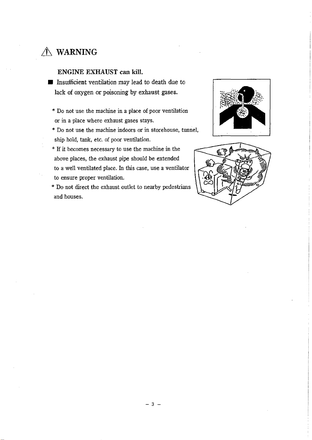
ENGINE EXHAUST can ill.
I Insufficient ventilation may lead to death due to
lack of oxygen or poisoning y exhaust gases.
* Do not use the machine in a place of poor ventilation
or in a place where exhaust gases stays.
* Do not use the machine indoors or in storehouse, tunnel,
ship hold, tank, etc. of poor ventilation.
* If it ecomes necessary to use the machine in the
a ove places, the exhaust pipe should e extended
to a well ventilated place. In this case, use a ventilator
to ensure proper ventilation.
* Do not direct the exhaust outlet to near y pedestrians
and houses.
- 3 -

A WARNING
ELECTRIC SHOCK can ill.
■ Do not touch the output terminals during operation
to prevent decease due to electric shock.
* Never touch the output terminals during operation.
If your hands or the machine are wet, it will result
in a death or serious injury.
* When a wiring work is required, e sure to turn OFF
the circuit reaker and stop the machine.
* Keep the output terminal cover closed and the terminal
olts tightened while the machine is running.
* A low voltage is generated even when the machine is
in low speed idle operation.
Be sure to stop the machine completely.
■ Do not touch the electrical parts in the machine during operation, as it may
lead to death due to electric shock.
* Always close the control panel and tighten the fixing olts efore operating the machine.
* Always close the side door and lock it efore operating the machine.
* When opening the control panel for voltage selection, etc., turn OFF the circuit reaker
and stop the machine.
A WARNING
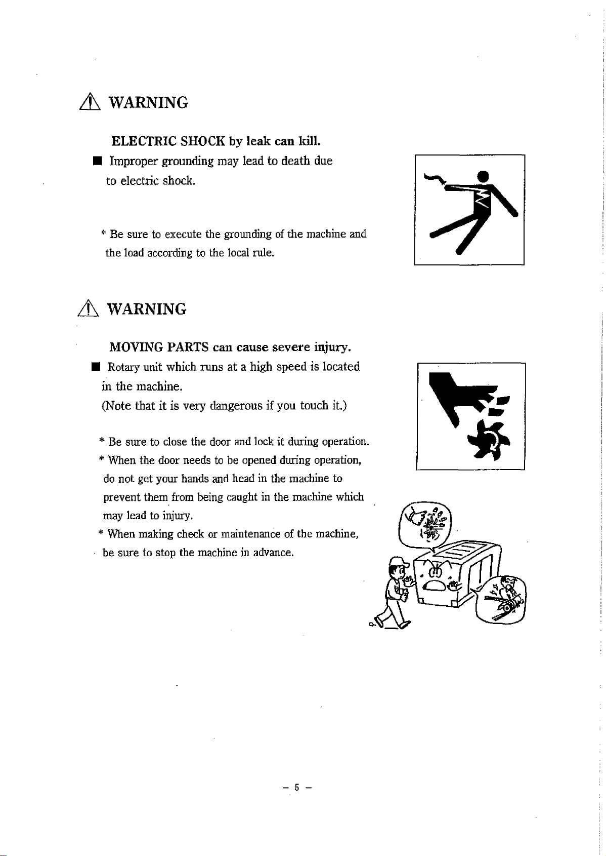
ELECTRIC SHOCK by lea can ill.
■ Improper grounding may lead to death due
to electric shock.
* Be sure to execute the grounding of the machine and
the load according to the local rule.
A WARNING
MOVING PARTS can cause severe injury.
■ Rotary unit which runs at a high speed is located
in the machine.
(Note that it is very dangerous if you touch it.)
* Be sure to close the door and lock it during operation.
* When the door needs to e opened during operation,
do not get your hands and head in the machine to
prevent them from eing caught in the machine which
may lead to injury.
* When making check or maintenance of the machine,
he sure to stop the machine in advance.
- 5 -

Ж WARNING
DIESEL FUEL can cause fire or explosion.
I Fuel and oil are flamma le. Incorrect handling
results in danger of ignition or fire.
* When fuel needs to e supplied to the machine,
e sure to stop the engine. Refrain from smoking.
Keep the machine away from fire.
* Do not leave flamma le o jects (paper, wood chips,
etc.) and hazardous o jects (oil, powder, etc.) near
the machine.
* Wipe off spilt fuel and oil.
Ж WARNING
HOT COOLANT can cause severe scalds.
I If the radiator cap is opened while the water
temperature is high, steam or hot water will
spout out.
* During operation or immediately after stopping the
machine, do not open the radiator cap while the
water temperature is high.
* When cooling water needs to e checked or supplied,
wait until the engine is cooled (50 °C or less as
measured with the water temperature gauge).
- 6 -

A CAUTION
Stac ing
■ Improper stacking of machines may cause falling or dropping accidents.
When stacking other machines on this machine, e sure to o serve the following
points.
* Check that the onnet of the machine is free from damage
and that the fixing olts are not loosened and missing.
* Put the machine horizontally on a solid foundation which withstands the weight of
stacked machines.
* Machines can e stacked up to 2 stages.
The weight and size of stacked machines should
e less than those of this machine.
* Using square tim ers as shown right, put each
machine making sure that the weight is even.
Ш Do not operate the machines in the state of
stacking to prevent falling or dropping accidents.
A CAUTION
\ %F=f
5R
V//V 7
HOT PARTS can burn s in.
High temperature units are located in the machine.
(Note that these units are very dangerous if they are
used incorrectly.)
* Be sure to close the door and lock it during operation.
* If the door needs to e opened during operation,
do not get your hands and head in the machine to
prevent unexpected ums.
* When making check or maintenance of the machine,
e sure to stop the machine.
* The onnet is still hot even after the machine is
stopped.
Be careful until the engine is completely cooled.
- 1 ~

Ж CAUTION
BATTERY
I Battery generates flamma le gases.
Improper handling may lead to explosion
or serious injury.
* Battery should e charged in a well ventilated
location. Otherwise, flamma le gases are
accumulated which may e ignited and exploded.
* When connecting a ooster ca le, do not jumper
the terminals (+ and -). Otherwise, the flamma le
gases generated from the attery may e ignited
and exploded y sparks.
* For maintenance of the machine, disconnect the
ground ca le on the ground side.
I The attery acid is dilute sulfuric acid. Improper
handling will cause unexpected ums.
* When the attery acid gets on your clothes or skin, wash it out with a large volume of
water immediately. If it gets in your eyes, wash with a large volume of water
immediately and consult your doctor.
- In the worst case, it will put out your eyes.
■ For checking or handling of the attery, e sure to stop the engine in advance.
- 8 -
A CAUTION
Operator
■ Do not operate the machine, if operator is tired too much or drinks some
alcohol or take some drugs.
* Otherwise, it may cause unexpected accidents or injury.
Ш During checking or maintenance, e sure to put on suita le clothes and protectors.
* Do not put on aggy clothes, necklace, etc., ecause they are easily caught y
projections which may cause injuries.
A CAUTION
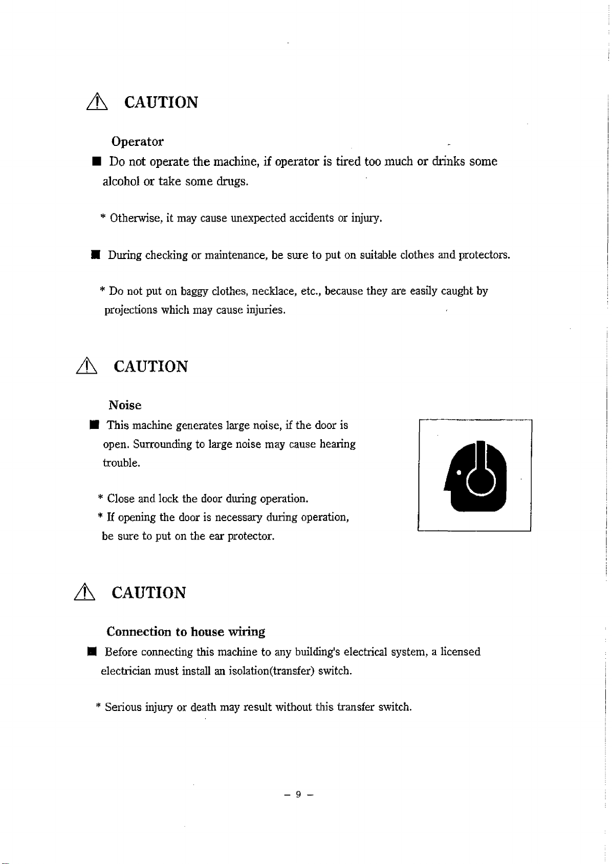
Noise
■ This machine generates large noise, if the door is
open. Surrounding to large noise may cause hearing
trou le.
* Close and lock the door during operation.
* If opening the door is necessary during operation,
e sure to put on the ear protector.
A CAUTION
Connection to house wiring
■ Before connecting this machine to any uilding's electrical system, a licensed
electrician must install an isolation(transfer) switch.
* Serious injury or death may result without this transfer switch.
- 9 -
A CAUTION
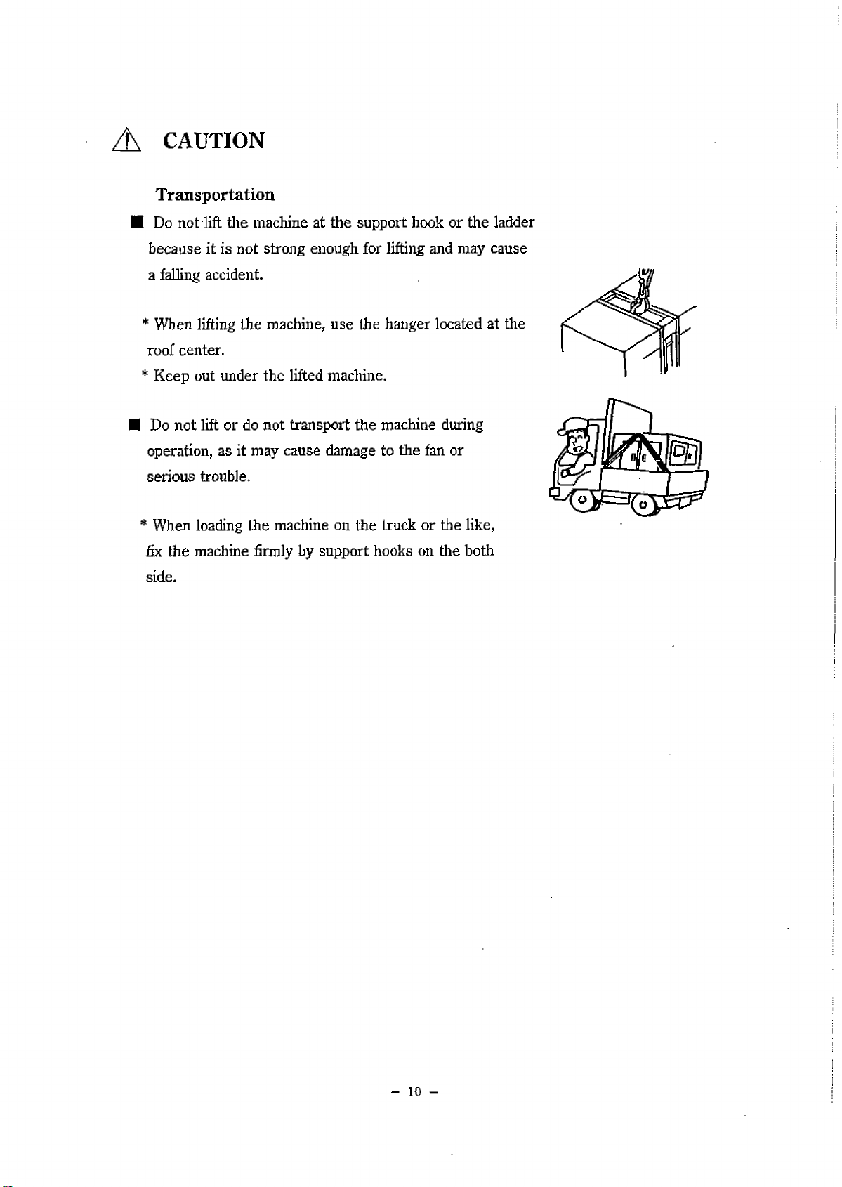
Transportation
■ Do not lift the machine at the support hook or the ladder
ecause it is not strong enough for lifting and may cause
a falling accident.
* When lifting the machine, use the hanger located at the
roof center.
* Keep out under the lifted machine.
I Do not lift or do not transport the machine during
operation, as it may cause damage to the fan or
serious trou le.
* When loading the machine on the truck or the like,
fix the machine firmly y support hooks on the oth
side.
- 1 0 -

2. Construction
2-1 Outline and part names
1. output terminal
2. control panel
3. operating panel
4. engine indicator
5. fuel in
6. hanger rod
7. support hook
8. coolant in
9. fuel drain plug
10. oil drain plug
11. exhaust gas outlet
- 11 -
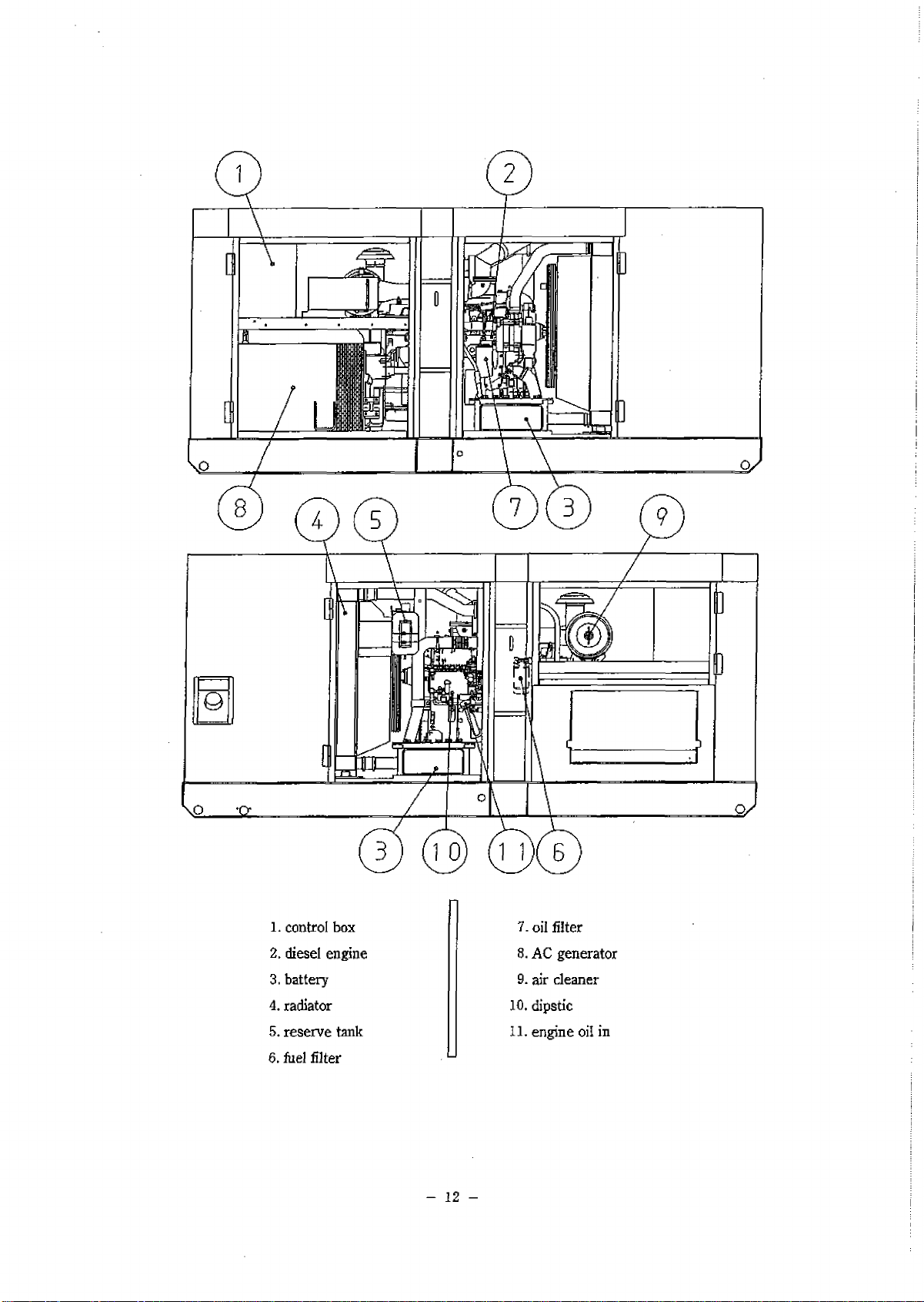
1. control ox
2. diesel engine
3. attery
4. radiator
5. reserve tank
6. fuel filter
7. oil filter
8. AC generator
9. air cleaner
10. dipstic
11. engine oil in
- 1 2 -
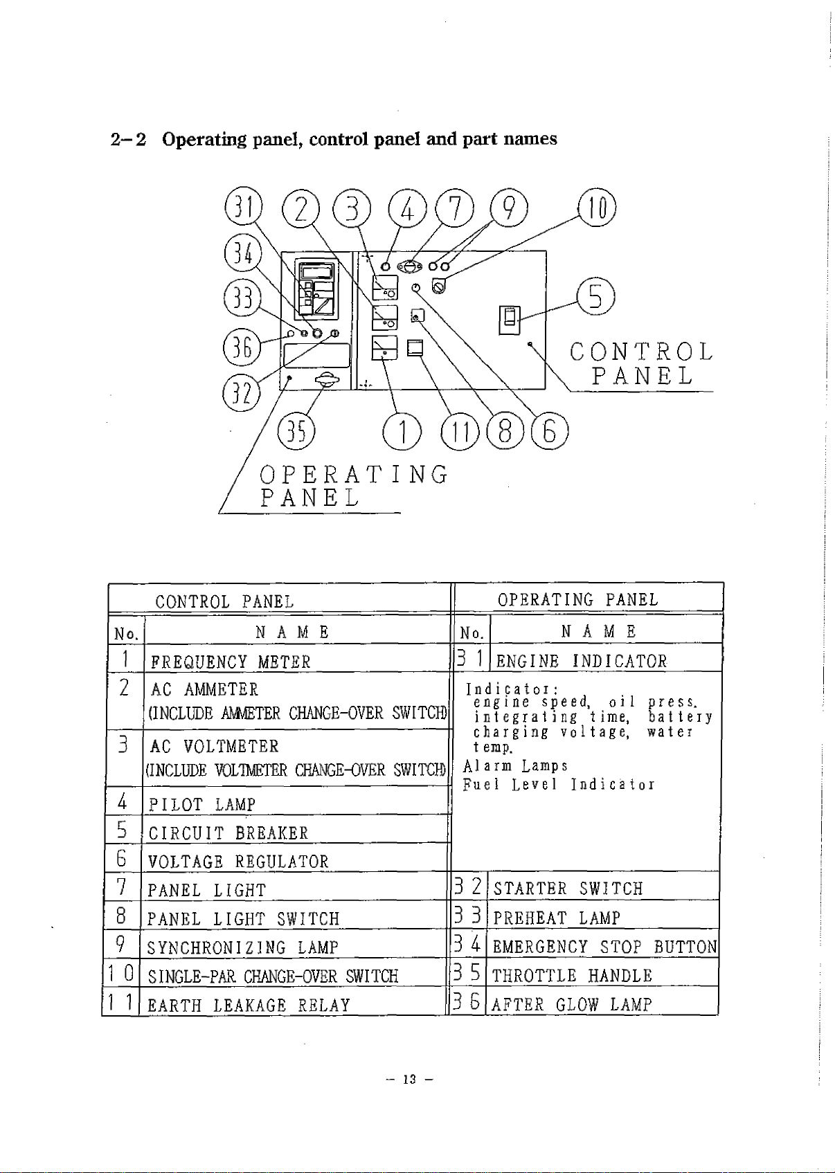
2 - 2 Operating panel, control panel and part names
OPERATING
PANEL
CONTROL
PANEL
CONTROL PANEL OPERATING PANEL
No. N A M E No. NAME
1FREQUENCY METER 3 1 ENGINE INDICATOR
2 AC AMMETER
(INCLUDE AMMETER CHANGE-OVER SWITCH) In<
er
i ii i с a t o i :
lgine speed, oil press,
it
egr a t i ng t ime, attery
larging voltage, water
mp.
mn Lamps
I T Duel ТпЯтро
+
лг
3AC VOLTMETER
(INCLUDE VOLTMETER CHANGE-OVER SWITCH)
с I
t e
A1
k
PILOT LAMP
5CIRCUIT BREAKER
6VOLTAGE REGULATOR
7PANEL LIGHT 3 2 STARTER SWITCH
8PANEL LIGHT SWITCH
m
nn
PREHEAT LAMP
9SYNCHRONIZING LAMP 3
i
EMERGENCY STOP BUTTON
1 0 SINGLE-PAR CHANGE-OVER SWITCH
i_n
m
THROTTLE HANDLE
1 1 EARTH LEAKAGE RELAY 3 6 AFTER GLOW LAMP
- 13 -

2 - 3 Meters
Engine indicators
Number Indicator
(1) Num er Indicator
That indicates the numerical values of engine speed, engine oil pressure,
run hours, attery charging voltage, or engine coolant temperature,
Each indication is selecta le y pushing the " SELECT " utton.
Unit Indicated Items
min'’ engine speed
X ЮОкРа engine oil pressure
hour run hours
Vattery charging voltage
Vengine coolant temperature
AUTO automatic indication change
Unless " SELECT " switch is pushed, " Engine Speed " is always
indicated immediately after engine starts
- 14 -

With " AUTO " selected, indication is automatically changed every
three (3) seconds.
- 1 - Engine Speed
Revolutions per minute is indicated.
XSOOmin -1 is indicated at 50Hz and 1800 min -1 is indicated at 60Hz.
- 2 - Engine Oil Pressure
2 to б X 100 kPa ( 2 to 6 kg / cm1 ) should e indicated at normal
engine operation. Higher value would e indicated in cold condition
immediately after engine starts. Conduct a wanning - up operation
until it indicates normal value.
- 3 - Run Hours
That indicated total running hours.
- 4 - Battery Charging Voltage
That should indicate more than 26V at engine running.
- 5 - Engine Coolant Temperature
That should indicate a temperature etween 75 to 90 °C at engine running.
Note ; If that would indicate higher temperature, disconnect all loads,
decrease the speed for cool - down operation, and wait until the
temperature comes down to normal value.
- 6 - Automatic Indication Change
Each of the a ove - started indications from the - 1 - to - 5 - changes y turns
every 3 seconds.
(2) Fuel Level Indicator
That Indicates a fuel level in the fuel tank. Green lamps will turn on with full tank.
As the fuel level drops, the num ers of the turn - on lamps decrease and at the
sametime the color of lamps changes from green to red.
Replenish the tank when there ecomes only one lamp turned on.
The ta le elow shows the relation etween num ers of turn - on lamps and feul level.
- 15 -
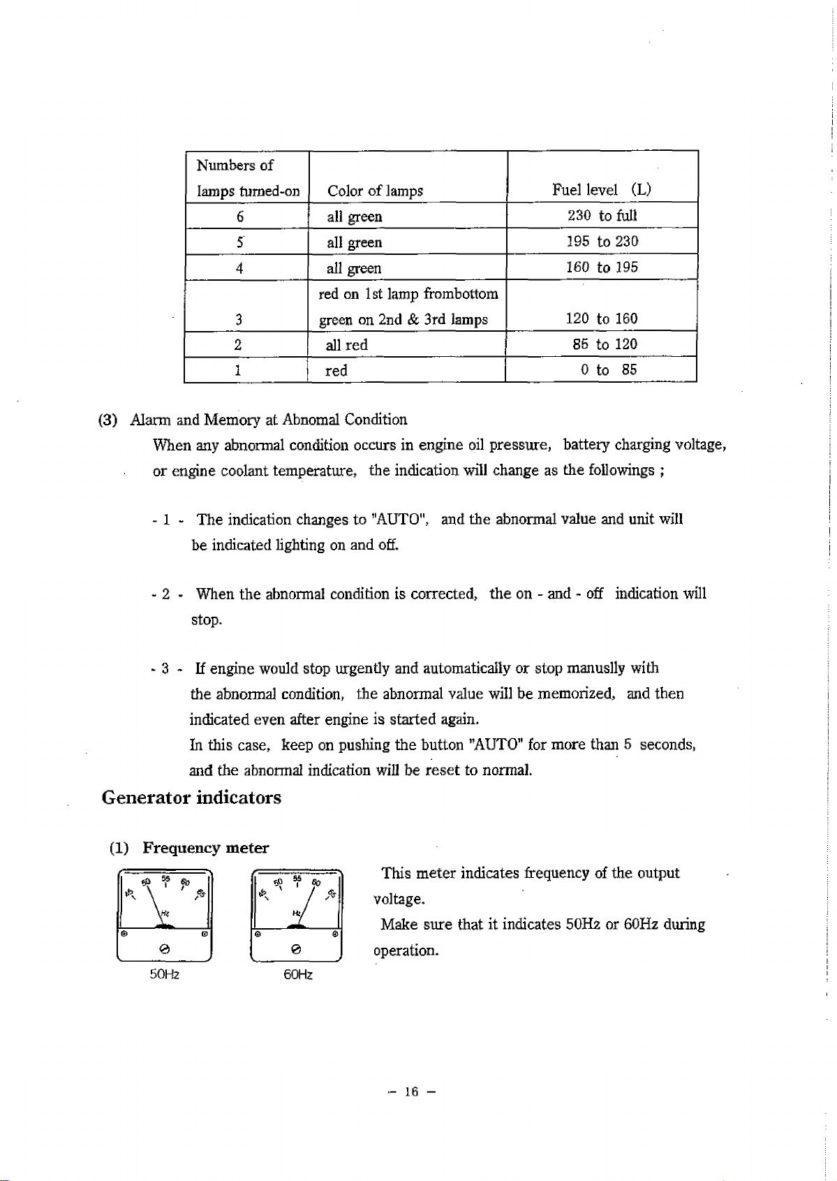
Num ers of
lamps tumed-on Color of lamps Fuel level (L)
6all green 230 to full
5all green 195 to 230
4all green 160 to 195
3
red on 1st lamp from ottom
green on 2nd & 3rd lamps 120 to 160
2 all red 85 to 120
1red 0 to 85
(3) Alarm and Memory at A nomal Condition
When any a normal condition occurs in engine oil pressure, attery charging voltage,
or engine coolant temperature, the indication will change as the followings ;
- 1 - The indication changes to "AUTO", and the a normal value and unit will
e indicated lighting on and off.
- 2 - When the a normal condition is corrected, the on - and - off indication will
stop.
- 3 - If engine would stop urgently and automatically or stop manuslly with
the a normal condition, the a normal value will e memorized, and then
indicated even after engine is started again.
In this case, keep on pushing the utton "AUTO" for more than 5 seconds,
and the a normal indication will e reset to normal.
Generator indicators
(1) Frequency meter This meter indicates frequency of the output
voltage.
Make sure that it indicates 50Hz or 60Hz during
operation.
60Hz
- 16 -
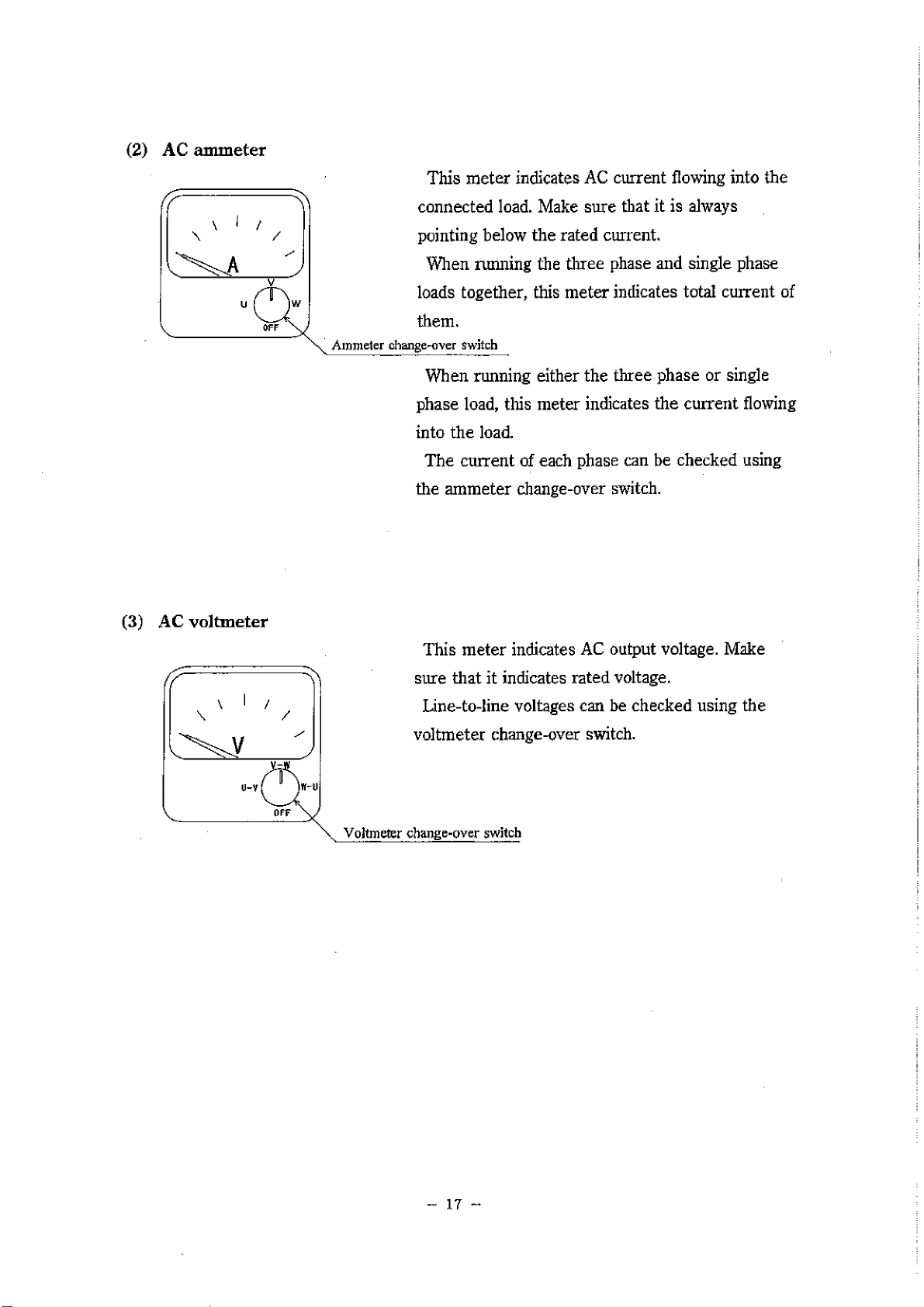
AC ammeter This meter indicates AC current flowing into the
connected load. Make sure that it is always
pointing elow the rated current.
When miming the three phase and single phase
loads together, this meter indicates total current of
them.
Ammeter change-over switch
When running either the three phase or single
phase load, this meter indicates the current flowing
into the load.
The current of each phase can e checked using
the ammeter change-over switch.
(3) AC voltmeter
This meter indicates AC output voltage. Make
sure that it indicates rated voltage.
Line-to-line voltages can e checked using the
voltmeter change-over switch.
Voltmeter change-over switch
- 17 -

Indication/alarm lamp
(1) Preheat lamp
It will automatically preheating device. If turn the starter
switch to "Run" position, it will according to cooling water
(coolant) temperature with the preheat lamp goes on.
When the preheat lamp goes off, it indicates that preheating
is completed.
(2) Warning Lamps
This monitor indicates the following failures, if any one of them occurs.
Ф High jacket water temperature (WATER TEMP)
This lamp goes on when the water temperature rises a normally.
If the lamp goes on during operation, the emergency stop device
immediately operates to shut down the engine automatically.
The engine control unit will sometimes cause a temporal indication of
the light when operating the starter switch, ut it is not related to any
of the warming.
(2) Oil pressure failure (OIL PRESS)
OIL PRESS If this lamp goes on during operation, the emergency stop device
immediately operates to shut down the engine automatically.
WATER TEMP
AIR FILTER ® filter lockage (AIR FILTER)
When the air element is lockage, this lamp goes on. Indicating that
the element should e cleaned or replaced.
(3) After Glow LampThe After Glow Lamp will e indicated and the engine will e heated
automatically when the water temperature remains less than 30°C.
This procedure will e carried unless it reaches more than 30X) or
glowing maximum for 3 minutes, and then automatically stop glowing
at the same time of stop indicating.
- 18 -

2- 4 Use of switches and controllers
Switches
Functions:
(D Stop
This switch should e set in this position unless the
machine is in operation. The key can e inserted or pulled
out in this position.
© Run
This switch should e set in this position when the
machine is in operation.
© Start
This is the position to start the engine. When your hand is
released from the key after starting, it is automatically set
in the position of "RUN”.
© Preheat
This is the position to start the engine when the air
temperature is low. Set the switch in this position until
the preheat lamp ecomes red heated, and then set it in the
start position.
(2)ThrottIe handle {Speed Control Handle)
Turn the handle toward the "HIGH" side to increase the speed
and toward the "LOW" side to decrease it.
- 1 -
(l)Starter switch
Table of contents
Other Denyo Portable Generator manuals

Denyo
Denyo DCA-150LSKE User manual

Denyo
Denyo DCA-25USI User manual

Denyo
Denyo DCA-30ESX User manual

Denyo
Denyo DCA-600P User manual

Denyo
Denyo DCA-13ESK User manual

Denyo
Denyo DCA-SP Series User manual

Denyo
Denyo DCA-13LSK User manual

Denyo
Denyo DCA-600SPK User manual

Denyo
Denyo DCA-60ESI2 User manual

Denyo
Denyo DCA Series User manual


