Denyo DCA-60ESI2 User manual

INSTRUCTION MANUAL
D EN YO
DIESEL GENERATING SETS
Before using, be sure to read this manual for the sake of safety.
Be sure to observe the items under symbol marks -A WARNING
and ■A CAUTION for the sake of safety.
Always keep this manual at your machine for the sake of safety.
DCA-6 О ES I 2
По вопросам продаж и поддержки обращайтесь:
Эл. почта: dne@nt-rt.ru || Сайт: https://denyo.nt-rt.ru/
Архангельск (8182)63-90-72
Астана +7(7172)727-132
Астрахань (8512)99-46-04
Барнаул (3852)73-04-60
Белгород (4722)40-23-64
Брянск (4832)59-03-52
Владивосток (423)249-28-31
Волгоград (844)278-03-48
Вологда (8172)26-41-59
Воронеж (473)204-51-73
Екатеринбург (343)384-55-89
Иваново (4932)77-34-06
Ижевск (3412)26-03-58
Иркутск (395) 279-98-46
Киргизия (996)312-96-26-47
Казань (843)206-01-48
Калининград (4012)72-03-81
Калуга (4842)92-23-67
Кемерово (3842)65-04-62
Киров (8332)68-02-04
Краснодар (861)203-40-90
Красноярск (391)204-63-61
Курск (4712)77-13-04
Липецк (4742)52-20-81
Магнитогорск (3519)55-03-13
Москва (495)268-04-70
Мурманск (8152)59-64-93
Набережные Челны (8552)20-53-41
Нижний Новгород (831)429-08-12
Казахстан (772)734-952-31
Новокузнецк (3843)20-46-81
Новосибирск (383)227-86-73
Омск (3812)21-46-40
Орел (4862)44-53-42
Оренбург (3532)37-68-04
Пенза (8412)22-31-16
Пермь (342)205-81-47
Ростов-на-Дону (863)308-18-15
Рязань (4912)46-61-64
Самара (846)206-03-16
Санкт-Петербург (812)309-46-40
Саратов (845)249-38-78
Севастополь (8692)22-31-93
Симферополь (3652)67-13-56
Таджикистан (992)427-82-92-69
Смоленск (4812)29-41-54
Сочи (862)225-72-31
Ставрополь (8652)20-65-13
Сургут (3462)77-98-35
Тверь (4822)63-31-35
Томск (3822)98-41-53
Тула (4872)74-02-29
Тюмень (3452)66-21-18
Ульяновск (8422)24-23-59
Уфа (347)229-48-12
Хабаровск (4212)92-98-04
Челябинск (351)202-03-61
Череповец (8202)49-02-64
Ярославль (4852)69-52-93

1. Safety Precautions
In order to ensure safe operation, the following sy bols are used for explanation of
the achine operation.
The following sy bols, found throughout this anual, alert you to potentially
dangerous conditions to the operator, service personnel, or the equip ent.
A WARNING: This sy bol refers to a hazard or unsafe practice which can result
in severe personal injury or death.
A CAUTION: This sy bol refers to a hazard or unsafe practice which can result
in personal injury or product or property da age.
[Note] : This sy bols show handling precautions for effective
operation and any years of satisfactory operation.
So e of the ite s shown by "/N CAUTION" ay also cause death or serious injury.
Be sure to observe all the ite s, as they are i portant for safe operation.
* If the achine is used by an outsider, you are requested to explain hi correct
handling and advise hi to read this instruction anual carefully.
* Do not odify the achine at your discretion, as it affects the safety, perfor ance
or the life of the achine.
* If the achine is odified or it is used incorrectly against this anual or
unauthorized parts are used, the warranty of anufacturer will beco e invalid.
- 1 -

Safety label
Safety labels are attached to the following positions of the achine.
* Keep these safety labels clean at all ti es.
* When safety labels are spoiled or lost, contact distributor or our office specifying the
na eplate No. shown below and ask for new ones.
No. Parts name Parts number
1 Safety instruction B9211 0140
2 Warning : moving parts B9050 0050
3 Warning : hot coolant B9051 0030
4Caution : exhaust gas B9052 0000
5 Warning : hot surfaces B9052 0020
6 Warning : diesel fuel B9055 0070A
7Warning : electric shock B9211 0150
CONTROL PANEL
- 2 -

A WARNING
ENGINE EXHAUST can kill.
1 Insufficient ventilation ay lead to death due to
lack of oxygen or poisoning by exhaust gases.
* Do not use the achine in a place of poor ventilation
or in a place where exhaust gases stays.
* Do not use the achine indoors or in storehouse, tunnel,
ship hold, tank, etc. of poor ventilation.
* If it beco es necessary to use the achine in the
above places, the exhaust pipe should be extended
to a well ventilated place. In this case, use a ventilator
to ensure proper ventilation.
* Do not direct the exhaust outlet to nearby pedestrians
and houses.
- 3 -

Ж WARNING
ELECTRIC SHOCK can MIL
■ Do not touch the output ter inals during operation
to prevent decease due to electric shock.
* Never touch the output ter inals during operation.
If your hands or the achine are wet, it will result
in a death or serious injuiy.
* When a wiring work is required, be sure to turn OFF
the circuit breaker and stop the achine.
* Keep the output ter inal cover closed and the ter inal
bolts tightened while the achine is running.
* A low voltage is generated even when the achine is
in low speed idle operation.
Be sure to stop the achine co pletely.
■ Do not touch the electrical parts in the achine during operation, as it ay
lead to death due to electric shock.
*Always close the control panel and tighten the fixing bolts before operating the
achine.
* Always close the side door and lock it before operating the achine.
* When opening the control panel for voltage selection, etc., turn OFF the circuit
breaker and stop the achine.
- 4 -

Ж WARNING
ELECTRIC SHOCK by leak can kill.
I proper grounding ay lead to death due
to electric shock.
* Be sure to execute the grounding of the achine and
the load according to the local rule.
A WARNING
MOVING PARTS can cause severe injury.
1 Rotary unit which runs at a high speed is located
in the achine.
(Note that it is very dangerous if you touch it.)
* Be sure to close the door and lock it during operation.
* When the door needs to be opened during operation,
do not get your hands and head in the achine to
prevent the fro being caught in the achine which .
ay lead to injury.
* When aking check or aintenance of the achine,
be sure to stop the achine in advance.
- 5 -

Ж WARNING
DIESEL FUEL can cause fire or explosion.
H Fuel and oil are fla able. Incorrect handling
results in danger of ignition or fire.
* When fuel needs to be supplied to the achine,
be sure to stop the engine. Refrain fro s oking.
Keep the achine away fro fire.
* Do not leave fla able objects (paper, wood
chips, etc.) and hazardous objects (oil, powder, etc.)
near the achine.
* Wipe off spilt fuel and oil.
Ж WARNING
HOT COOLANT can cause severe scalds.
Ш If the radiator cap is opened while the water
te perature is high, stea or hot water will
spout out.
* During operation or i ediately after stopping the
achine, do not open the radiator cap while the
water te perature is high.
* When cooling water needs to be checked or
supplied, wait until the engine is cooled (50°C or
less as easured with the water te perature gauge).
(4 j>
- 6 -

A CAUTION
Stacking
I I proper stacking of achines ay cause falling or dropping accidents.
When stacking other achines on this achine, be sure to observe the
following points.
* Check that the bonnet of the achine is free fro da age
and that the fixing bolts are not loosened and issing.
* Put the achine horizontally on a solid foundation which withstands the weight of
stacked achines.
* Machines can be stacked up to 2 stages.
The weight and size of stacked achines should
be less than those of this achine.
* Using square ti bers as shown right, put each
achine aking sure that the weight is even.
□ c
□ c
'7/7777/7/77777/7/ ///7/777///
Do not operate the achines in the state of
stacking to prevent falling or dropping accidents.
A CAUTION
HOT PARTS can burn skin.
1 High te perature units are located in the achine.
(Note that these units are very dangerous if they are
used incorrectly.)
* Be sure to close the door and lock it during operation.
* If the door needs to be opened during operation,
do not get your hands and head in the achine to
prevent unexpected bu s.
* When aking check or aintenance of the achine,
be sure to stop the achine.
* The bonnet is still hot even after the achine is
stopped.
Be careful until the engine is co pletely cooled.
~ 7 -

A CAUTION
BATTERY
■ Battery generates fla able gases.
I proper handling ay lead to explosion
or serious injury.
* Battery should be charged in a well ventilated
location. Otherwise, fla able gases are
accu ulated which ay be ignited and exploded.
* When connecting a booster cable, do not ju per
the ter inals (+ and -). Otherwise, the fla able
gases generated fro the battery ay be ignited
and exploded by sparks.
* For aintenance of the achine, disconnect the
ground cable on the ground side.
■ The battery acid is dilute sulfuric acid. I proper
handling will cause unexpected bu s.
* When the battery acid gets on your clothes or skin, wash it out with a large
volu e of water i ediately. If it gets in your eyes, wash with a large volu e of
water i ediately and consult your doctor.
- In the worst case, it will put out your eyes.
I For checking or handling of the battery, be sure to stop the engine in advance.
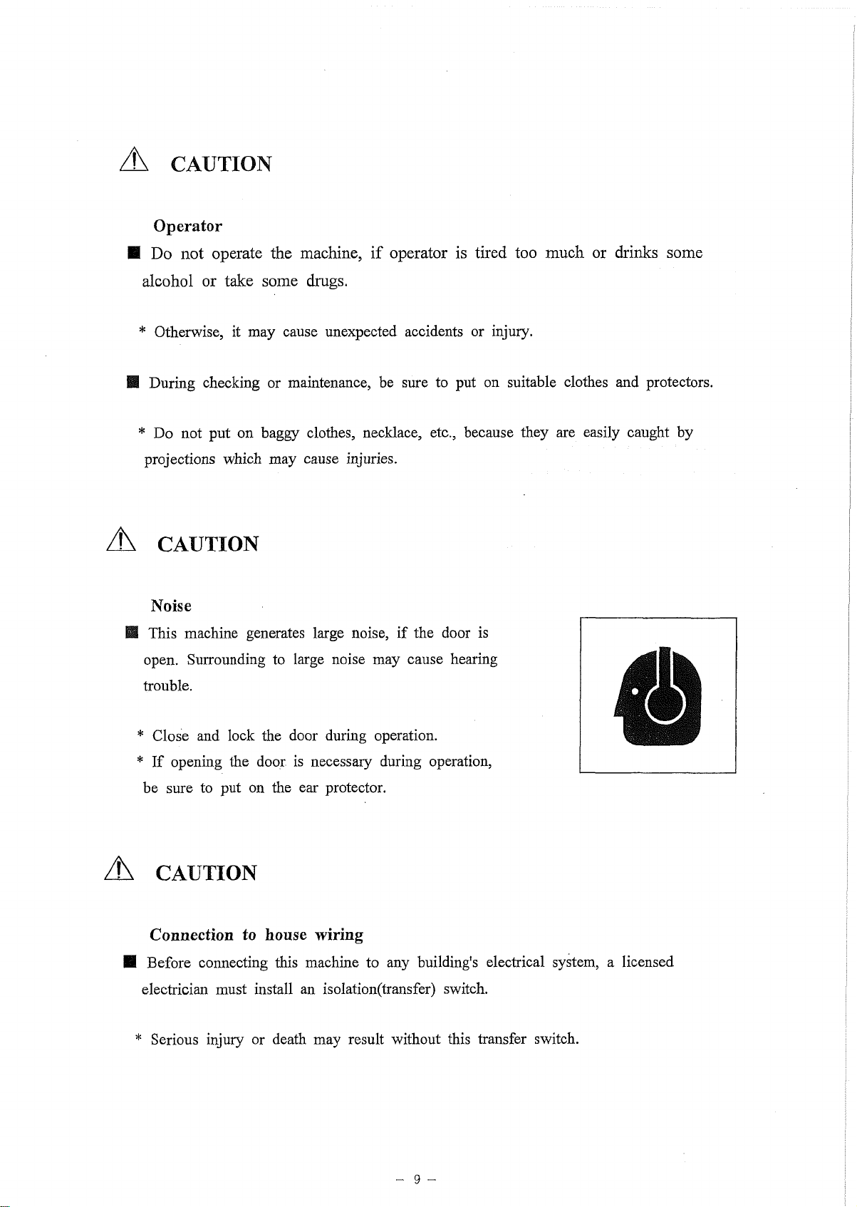
A CAUTION
Operator
■ Do not operate the achine, if operator is tired too uch or drinks so e
alcohol or take so e drugs.
* Otherwise, it ay cause unexpected accidents or injury.
■ During checking or aintenance, be sure to put on suitable clothes and protectors.
* Do not put on baggy clothes, necklace, etc., because they are easily caught by
projections which ay cause injuries.
A CAUTION
Noise
ffl This achine generates large noise, if the door is
open. Surrounding to large noise ay cause hearing
trouble.
* Close and lock the door during operation.
* If opening the door is necessary during operation,
be sure to put on the ear protector.
A CAUTION
Connection to house wiring
■ Before connecting this achine to any building's electrical syste , a licensed
electrician ust install an isolation(transfer) switch.
* Serious injury or death ay result without this transfer switch.

A CAUTION
Transportation
И Do not lift the achine at the support hook or the ladder
because it is not strong enough for lifting and ay cause
a falling accident..
* When lifting the achine, use the hanger located at the
roof center.
* Keep out under the lifted achine.
■ Do not lift or do not transport the achine during
operation, as it ay cause da age to the fan or
serious trouble.
* When loading the achine on the truck or the like,
fix the achine fir ly by support hooks on the both
side.
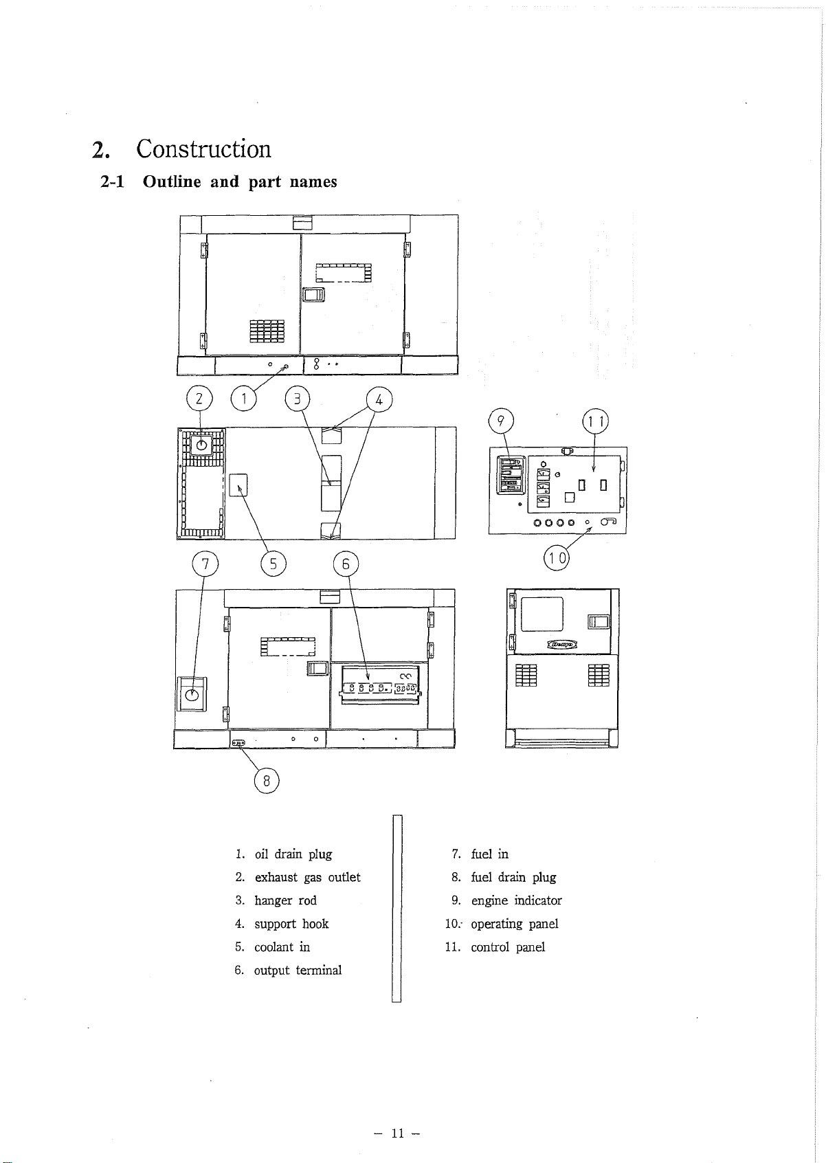
2. Construction
2-1 Outline and part names
1. oil drain plug
2. exhaust gas outlet
3. hanger rod
4. support hook
5. coolant in
6. output terminal
7. fuel in
8. fuel drain plug
9. engine indicator
10.- operating panel
11. control panel
- 11 -

1. air cleaner
2. oil filter
3. fuel filter
4. reserve tank
5. AC generator
6. diesel engine
7. radiator
8. oil level gauge
9. control box
10. fuel tank
11. battery
- 12 -
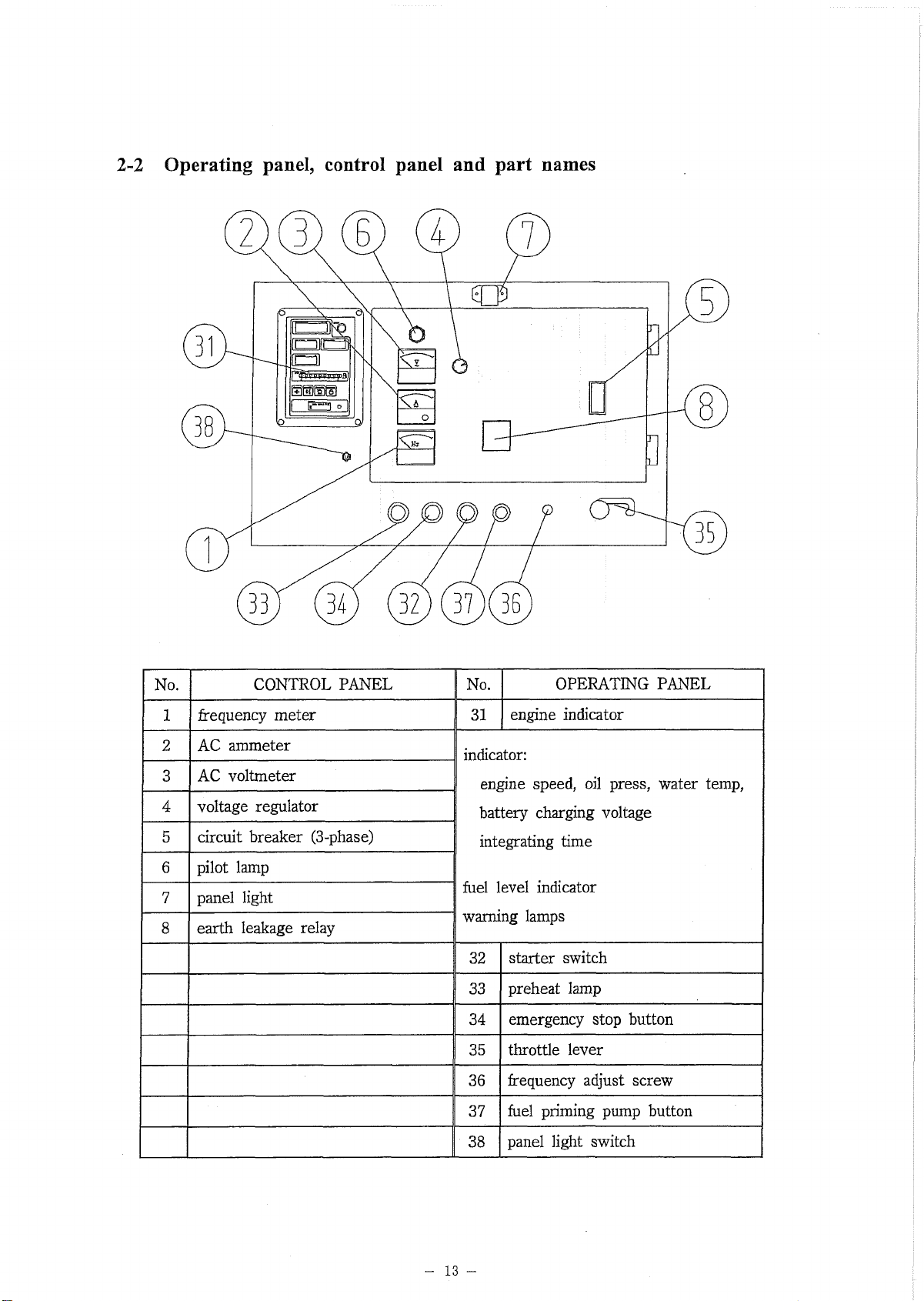
2-2 Operating panel, control panel and part names
No. CONTROL PANEL No. OPERATING PANEL
1frequency eter 31 engine indicator
2 AC a eter indicator:
3AC volt eter engine speed, oil press, water te p,
4voltage regulator battery charging voltage
5 circuit breaker (3-phase) integrating ti e
6pilot la p
7panel light fuel level indicator
warning la ps
8 earth leakage relay
32 starter switch
33 preheat la p
34 e ergency stop button
35 throttle lever
36 frequency adjust screw
37 fuel pri ing pu p button
38 panel light switch
- 13 -

2-3 Meters
Engine indicators
Fig.4
(1) Engine indicator
That indicates the nu erical values of engine speed, engine oil pressure, run hours,
battery charging voltage, or engine coolant te perature.
Indicated Ite s Unit
engine speed in"1
engine oil pressure X ЮОкРа
battery charging voltage V
engine coolant te perature °C
- 14 -

-1 - Engine Speed
Revolutions per inute is indicated. 1500 1 is indicated at 50Hz and 1800 in"1 is
indicated at 60Hz.
- 2 - Engine Oil Pressure
2 to 5 x 100 kPa should be indicated at nor al engine operation.
Higher value would be indicated in cold condition i ediately after engine starts.
Conduct a warning - up operation until it indicates nor al value.
- 3 - Battery Charging Voltage
That should indicate ore than 12.5V at engine running.
- 4 - Engine Coolant Te perature
That should indicate a te perature between 75 to 95 °C at engine running.
Note ; If that would indicate higher te perature, disconnect all loads, decrease
the speed for cool - down operation, and wait until the te perature co es down
to nor al value..
(2) Fuel Level Indicator
That Indicates a fuel level in the fuel tank. All the lights are indicated green when the fuel
is full.
The green lights stop indicating one by one as the fuel level decrease, finally the red light
will be indicated when it is only one green light is left.
Replenish the tank when there beco es only one la p turned on.
The table below shows the relation between nu bers of turn - on la ps and fuel level.
Nu bers of
la ps tu ed-on Fuel level (L)
9105 to full
890 to 105
780 to 90
665 to 80
555 to 65
445 to 55
3 35 to 45
2 25 to 35
10 to 25
- 15 -

(3) Alarm and Memory at Abnormal Condition
When any abnor al condition occurs in engine oil pressure, battery charging voltage,
or engine coolant te perature, the indication will change as the following;
- 1 - The Indicator shows its defect with blinking nu bers.
- 2 - When the abnor al condition is corrected, the on - and - off indication will stop.
- 3 - If engine would stop urgently and auto atically or stop anually with the abnor al
condition, the abnor al value will be e orized, and then indicated even after engine
is started again.
In this case, keep on pushing the button “RESET” for ore than 5 seconds, and the
abnor al indication will be reset to nor al.
(4) Hour Meter
® When you turn the starter switch to “RUN” position, and push the selector button
located on the right side of the Hour Meter, you can see the nu bers entioned
below;
■ “ODD” Total running hour
■ “TRIP 0 ” Running hours “A” on a certain period
• “TRIP [в]” Running hours “B” on a certain period
© If you want to reset the Trip Meters, push the selector button for ore than 1 second,
after selecting each eters.
- 16 -

(5) The hour meter has an internal battery
The engine onitor incorporates both a rechargeable internal batteiy as well as a
charging circuit.
While the generator is not in operation, the engine onitor will still indicate the
hours operated via its internal battery. While the generator is in operation, the internal
battery recharges.
When the generator re ains unused for a long period of ti e, the battery will
continue to lose its charge. Once the charge is exhausted, the hour eter will not
indicate hours, and the battery will need to be recharged. Fro a co pletely
exhausted state, recharging the battery for 30 inutes will only result in a 30
inute charge to the batteiy. However, if charged for 3 hours, the hour eter will in
dicate hours for ore than 10 days without another charge.
Please refer to the table below to see the relationship between battery ti e
charging versus length of indication by the hour eter.
- 17 -

Generator indicators
(1) Frequency meter
5,0 f So
* \
f \
5,0 s,5 6b
к
/
V±
© 0 © ©
0
V j
0J
50Hz 60Hz
This eter indicates frequency of the output
voltage.
Make sure that it indicates 50Hz or 60Hz during
operation.
(2) AC ammeter
This eter indicates AC current flowing into the
connected load. Make sure that it is always
pointing below the rated current.
When running the three phase and single phase
loads together, this eter indicates total current of
the .
When running either the three phase or single
phase load, this eter indicates the current flowing
into the load.
The current of each phase can be checked using
the a eter change over switch.
(3) AC voltmeter
50Hz 60Hz
f
..
...........
.
—:—-‘N
гФ
,
Jo г о р , y 0
\ y / ' &
'
SlL ' f°°
©
©
© ©
0
A
J
This eter indicates AC output voltage. Make
sure that it indicates rated voltage.
- 18 -

(1) Preheat lamp
This achine has auto atically preheating device.
If turn the starter switch to “RUN” position, it will according to
cooling water (coolant) te perature with the preheat la p goes on.
When the preheat la p goes off, it indicates that preheating is
co pleted.
(2) Warning Lamps
This onitor indicates the following failures, if any one of the occurs.
® High jacket water te perature (WATER TEMP)
This la p goes on when the water te perature rises abnor ally. If
the la p goes on during operation, the e ergency stop
device i ediately operates to shut down the engine auto atically.
Indication/alarm lamp
Ф Oil pressure failure (OIL PRESS)
If this la p goes on during operation, the e ergency stop device
i ediately operates to shutdown the engine auto atically.
(D Air filter blinding (AIR FILTER)
When the air ele ent is blinded, this la p goes on. Indicating that
the ele ent should be i ediately cleaned or replaced.
® Over speed of engine (OVER SPEED)
This la p goes on when the engine speed rises abnor ally. If the
la p goes on during operation, the e ergency stop device
i ediately operates to shut down the engine auto atically.
Table of contents
Other Denyo Portable Generator manuals

Denyo
Denyo DCA-13LSK User manual

Denyo
Denyo DCA-SP Series User manual

Denyo
Denyo DCA-150ESK User manual

Denyo
Denyo DCA Series User manual

Denyo
Denyo DCA-30ESX User manual

Denyo
Denyo DCA-6LSX User manual

Denyo
Denyo DCA-25USI User manual

Denyo
Denyo DCA-13ESK User manual

Denyo
Denyo DCA-150LSKE User manual

Denyo
Denyo DCA-600P User manual

Popular Portable Generator manuals by other brands


WATTBRICKS
WATTBRICKS MP330 user manual

SDMO
SDMO SH 6000-2 UK Generating set user and maintenance manual

DeVilbiss Air Power Company
DeVilbiss Air Power Company D26968 Operator's manual
 owner's manual")
Generac Power Systems
Generac Power Systems 005796-0 (XG6500) owner's manual

Alpha tools
Alpha tools STE 850 operating instructions

Sportsman
Sportsman GEN7000LP instruction manual