Derale 16720 User manual

16720-16721-InstructionSheet
Derale Performance, Los Angeles, CA 800.421.6288 www.derale.com
INSTALLATION INSTRUCTIONS
SINGLE STAGE ELECTRIC FAN THERMOSTAT
PART # 16720 & 16721
WIRING
Before starting, disconnect the Negative (-) cable on the vehicles battery.
Using the electrical connectors and wire ties provided, follow the directions below.
When extending wires always use the identical gauge wire as provided.
Using the Blue 5/16” Ring Terminal provided attach to the Positive (+) terminal of the battery.
Using the Blue #10 Ring Terminal and #10 Sheet Metal Screw provided attach to a good chassis ground (-).
Using the Blue Female Connector provided, attach the Yellow Wire to EITHER terminal on the Thermostat
Switch.
Using the Blue Female Connector, Blue Wire Tap Connector and Wire provided, attach the remaining
Thermostat Switch Lead to a Positive (+) switched ignition source.
Attaching this wire directly to a 12V non-switched source will allow the fan to run after the vehicle has been turned
off which could effect the vehicles battery performance.
The green wire is designed to work in two different configurations. When used, this will allow the fan(s) to
be turned on regardless of the temperature of the thermostat as it simply overrides all other functions. If you choose to not use
this option disregard the wire.
1. A/C Override - Using the Blue Wire Tap provided, attach the green wire to the positive (+) lead on the air conditioning
compressor.
2. Manual Switch Override - Attach the Green Wire to the manual switch NOT PROVIDED. (See Diagram #4 on page 2)
See page 2 for single or dual fan configurations.
WARNING:
See Diagrams#2&3onpage 2
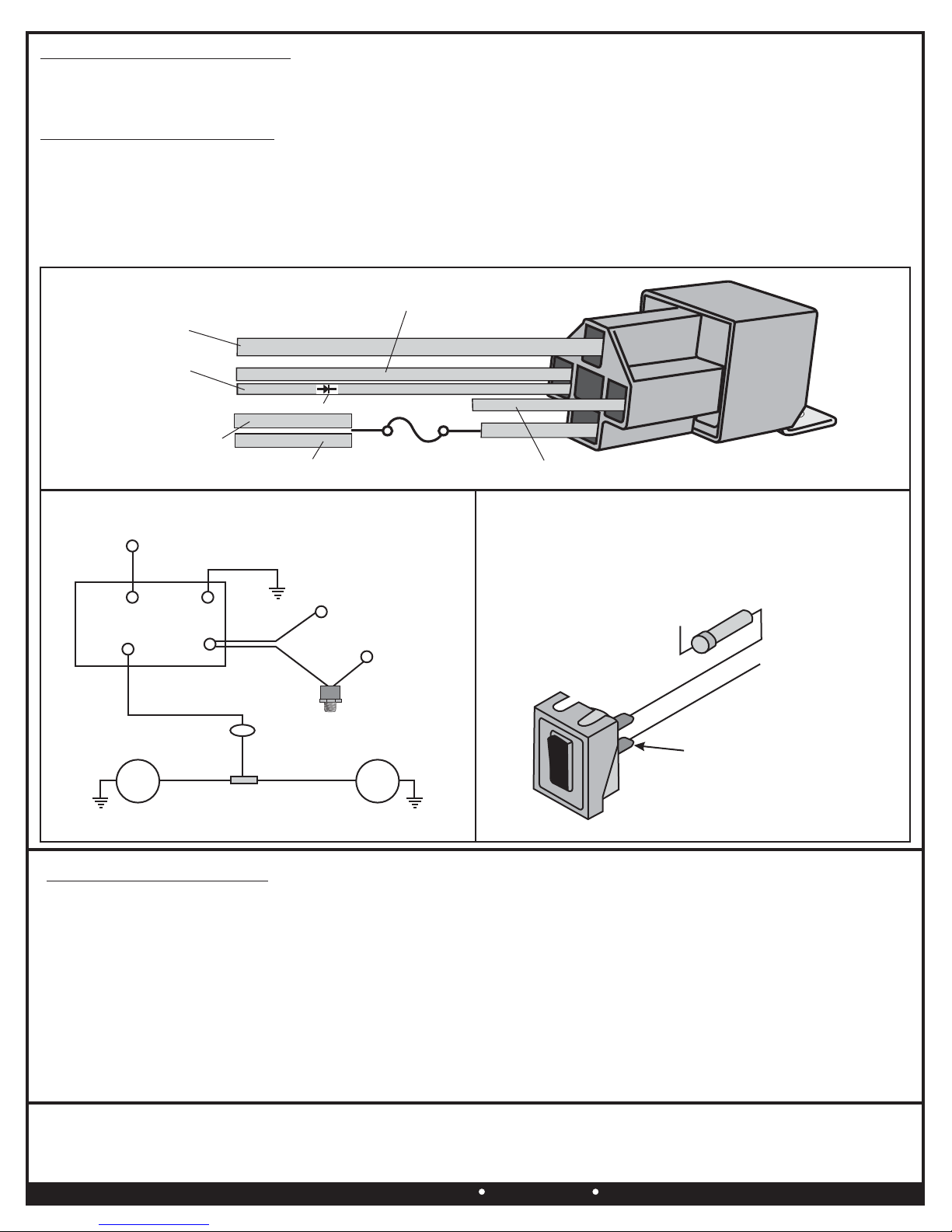
Red:
Black:
Yellow Wire -
Thermostat Switch -
Warning:
Green (Optional):
Orange/Blue Wires:
(Continues on reverse side)
Diagram #1
Please read these instructions completely before beginning installation
THERMOSTAT PROBE INSTALLATION
RELAY WIRE HARNESS MOUNTING
Placement: generally
1/8” NPT port installation -
3/8” NPT port installation -
Locate a port on the vehicle, found on the
vehicles radiator, manifold or water outlet.
Using Teflon Tape or suitable sealant
install the Thermostat Switch into the port on the vehicle.
Using Teflon Tape or suitable sealant
install the 3/8” x 1/8” NPT Reducer Bushing into the 3/8” NPT port on
the vehicle. Using Teflon Tape or suitable sealant install the Thermostat
Switch into the 3/8” x 1/8” NPT Reducer Bushing.
(See Diagram #1)
1. Taking into consideration probe placement and wire routing
requirements, choose a convenient location.
Avoid mounting near HOT engine components.
2. Using the relay bracket as a template, mark and drill a 5/32” hole in
the proper location.
3. Using the #10 Sheet Metal Screws provided, install the relay/wire
harness.
3/8”
NPT
3/8”
NPT
1/8”
NPT
1/8”
NPT
1/8”
NPT
1/8”
NPT
KIT CONTENTS
QTY. DESCRIPTION
1 1/8” NPT Thermostat Switch
1 Relay Wire Harness
1 3/8” x 1/8” Reducer Bushing
3 #10 Sheet Metal Screw
4 4” Wire Ties
1 Roll Extra Wire
QTY. DESCRIPTION
1 Blue 5/16” Ring Terminal
2 Blue #10 Ring Terminal
2 Blue Butt Connectors
2 Blue Female Connectors
2 Blue Wire Tap Connectors
IMPORTANT
This single stage electric fan thermostat will control up
to two different fans with a
If fans exceed
25 amps combined we recommend using one switch
per fan.
COMBINED MAXIMUM
DRAW OF 25 CONTINUOUS AMPS.
TOOLS NEEDED
12V Test Light
Wire Stripper
Crimping Tool
”5/8 Open End Wrench
11/16” Open End Wrench
Teflon Tape
Standard Screw Driver
or a 5/16” Nut Driver
Drill
5/32” Drill Bit
Derale Performance, Los Angeles, CA 800.421.6288 www.derale.com
Warning: Installation of accessories should only be undertaken by those with mechanical knowledge and are familiar with working on
vehicles. Always use eye protection (goggles, safety glasses or shield). Park the vehicle in a well lit area, on level ground and apply the
parking brake. Only work on a cold vehicle that has been sitting overnight, failure to do so will result in severe burns and injury. Before starting
the vehicle, make sure no tools or any other items are left under hood that could interfere with or be drawn into moving parts of the engine.
Failure to follow instructions can lead to severe damage and personal injury.
TROUBLE SHOOTING Q&A
Q: Why doesn’t the fan(s) turn on?
A: 1. Check all connections to make sure all contacts are crimped correctly.
2. Check all Ground (-) connections to make sure all paint is sanded off and you are getting a metal to metal contact.
Q: Why does the fan(s) run after the engine is turned off?
A: Check the wire going to the Thermostat Switch, this wire should be connected to a 12V Positive (+) switched ignition
source.
Q: Why doesn’t the fan(s) turn on when I use the Override function?
A: To quickly test the Override circuit, disconnect the Green Wire and run a jumper wire directly to the Positive (+) terminal on
the battery. The electric fan should start immediately. If fan started, reattach the Green Wire to the proper (+) wire on the
A/C clutch or Manual Switch.
Diagram #4
Diagram #2
Chassis
Ground (-)
Blue
Fan
Positive (+)
Orange
Fan
Positive (+)
30Amp Fuse
Chassis
Ground (-)
Ignition
Switch
Red
30 86
85
87
Green
Orange
Diagram #3
Yellow
For manual switch wiring, refer to
switch manufacturer instructions.
15Amp Fuse
+12V
Ignition Power
Green Wire
Manual Switch Override Instructions
(Switch Not Included)
Black
Chassis
Ground (-)
12 Volt Positive (+)
Battery
Thermostat
Switch
RELAY
Override Circuit
(Optional)
FAN MOTOR
#1
FAN MOTOR
#2
30amp Fuse
Red Wire
Battery Power
12V (+)
Black Wire
Chassis Ground (-)
Green Wire
Optional A/C
Override (+) One Way Diode
Orange Wire
Positive (+)
Fan Lead Blue Wire Optional Secondary Fan
Positive (+) Lead
Yellow Wire
to Thermostat Switch
then to 12V (+)
Ignition Switch
SINGLE FAN CONFIGURATION
DUAL FAN CONFIGURATION
Orange Wire:
Negative Fan Wire:
Blue Wire:
Fan #1
Orange Wire:
Fan #2
Blue Wire:
Negative Fan Wires: ,
Using a Blue Butt Connector provided attach the Orange wire to the Positive (+) electric fan lead.
Using a Blue Ring Terminal provided attach the Negative (-) electric fan lead to a good chassis ground (-).
Disregard, cut any exposed copper and tape or shrink wrap the end of the wire.
Using a Blue Butt Connector provided attach the Orange wire to the Positive (+) electric fan lead on fan #1.
Using a Blue Butt Connector provided attach the Blue wire to the Positive (+) electric fan lead on fan #2.
Using a Blue Ring Terminal provided attach BOTH Negative (-) electric fan leads to a good chassis ground (-).
Reattach the Negative (-) cable on the vehicles battery.
This manual suits for next models
1
Other Derale Thermostat manuals


