thermotouch 5215 Operation manual

Installation & User Guide
Manual thermostat for electric underfloor heating
Thermotouch Manual Glass
UNDERFLOOR HEATING CONTROLS
5215 / 5216

2
Contents
Compatibility ............................................................... 3
What’s in the box? ....................................................... 4
Before you start ........................................................... 5
Installing your thermostat ............................................... 6
Wiring diagram ............................................................ 11
Switching on your system .............................................. 13
Settings ...................................................................... 14
User interface .............................................................. 16
Technical data ............................................................. 17
Key lock ....................................................................... 18

3
Compatibility
Thermotouch Manual Glass is compatible with
Thermogroup NTC 10K floor sensor probes.
NTC 10kΩ@ 25°C
If your existing floor probe is from another thermostat
manufacturer and is not compatible, set your
thermostat to ambient temperature sensing mode.
(Not advisable for timber or other temperature sensitive floors).
Replacing an existing thermostat?
Contact the manufacturer’s technical department
and ask for the rating of the floor sensor at 25°C.

4
What’s in the box?
Check you’ve got everything:
• Manual thermostat (5215 or 5216)
• Floor sensor probe (3m)
• Floor sensor conduit (2m)
• Fixing screws
• Installation guide
You will also need:
• Electrical screwdriver
• Deep electrical back box
• Electrical test meter

5
Before you start
Your thermostat should be:
• Installed 1.2 - 1.5m from the floor
• On an interior wall
• Outside any wet zones (IP30)
• Installed on an RCD protected circuit
• Away from drafts or heat influences
• Installed so that the floor sensor probe
can be laid in a heated area of the floor
• Installed by a professional, in line
with current IEE 17th Edition Part P
regulations and local standards

6
Installing your thermostat
Fuse Box Fused Switch
CAUTION
High Voltage
Cables
!
1. Switch off mains power
You will be installing your thermostat as
part of a high voltage mains electrical
circuit. To ensure your safety and to protect
the thermostat, switch off the mains power
and remove fuse from the spur before you
start the installation.
OFF
ON ON ON ON ON
OFF

7
Installing your thermostat
2. Installation location
At this stage it its likely that an RCD
protected electric underfloor heating system
has been installed and a back box is
already in place.
The underfloor heating cold tail should
be pulled up through the back box, and
the sensor probe installed (in the conduit
provided) within the wall cavity or pre
chased channel in a solid wall.
8
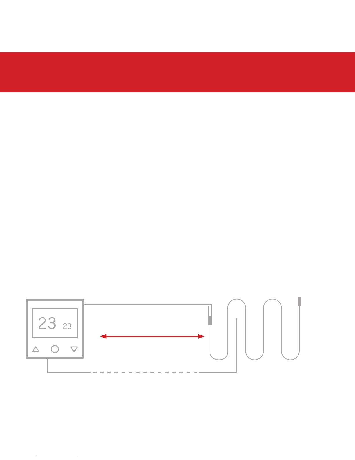
3. Maximum distances
Your thermostat can be installed up to 50m away from
the underfloor heating system it is controlling, provided
that the floor sensor is used to control the temperature.
Underfloor heating cold tails and floor sensor probes
can be extended up to 50m.
Connect multiple heaters to the thermostat in parallel.
50m max.
Installing your thermostat
9
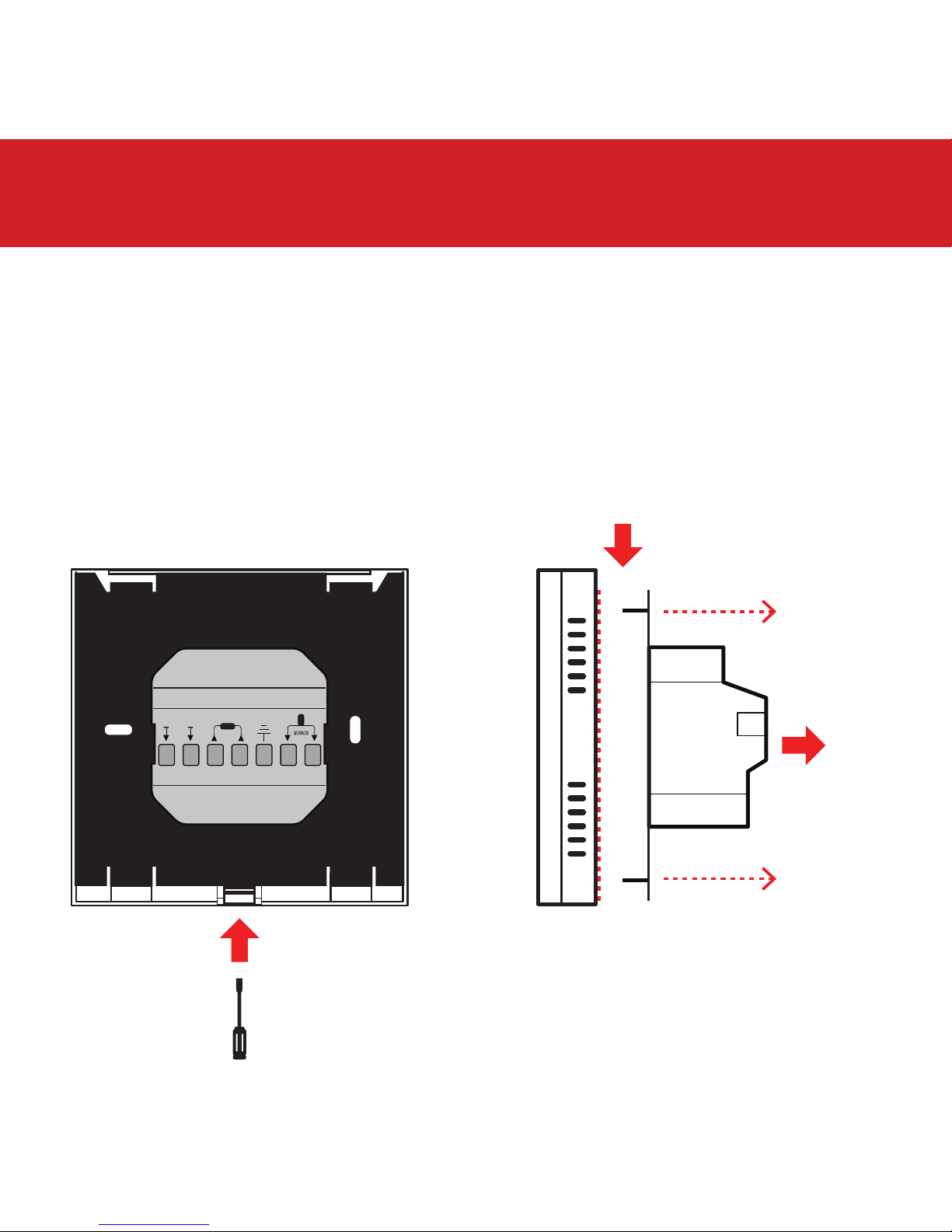
Installing your thermostat
4. Release mounting plate
Use a flat screwdriver to press in the catch (1) and push the fascia
down as shown (2) to release the clips holding the back plate and
the thermostat fascia together. Disconnect the white ribbon cable.
3600W/16A 230V/AC
2
1
3
Do not try to force the back plate off
without first pushing the fascia down
to relase the clips!
10
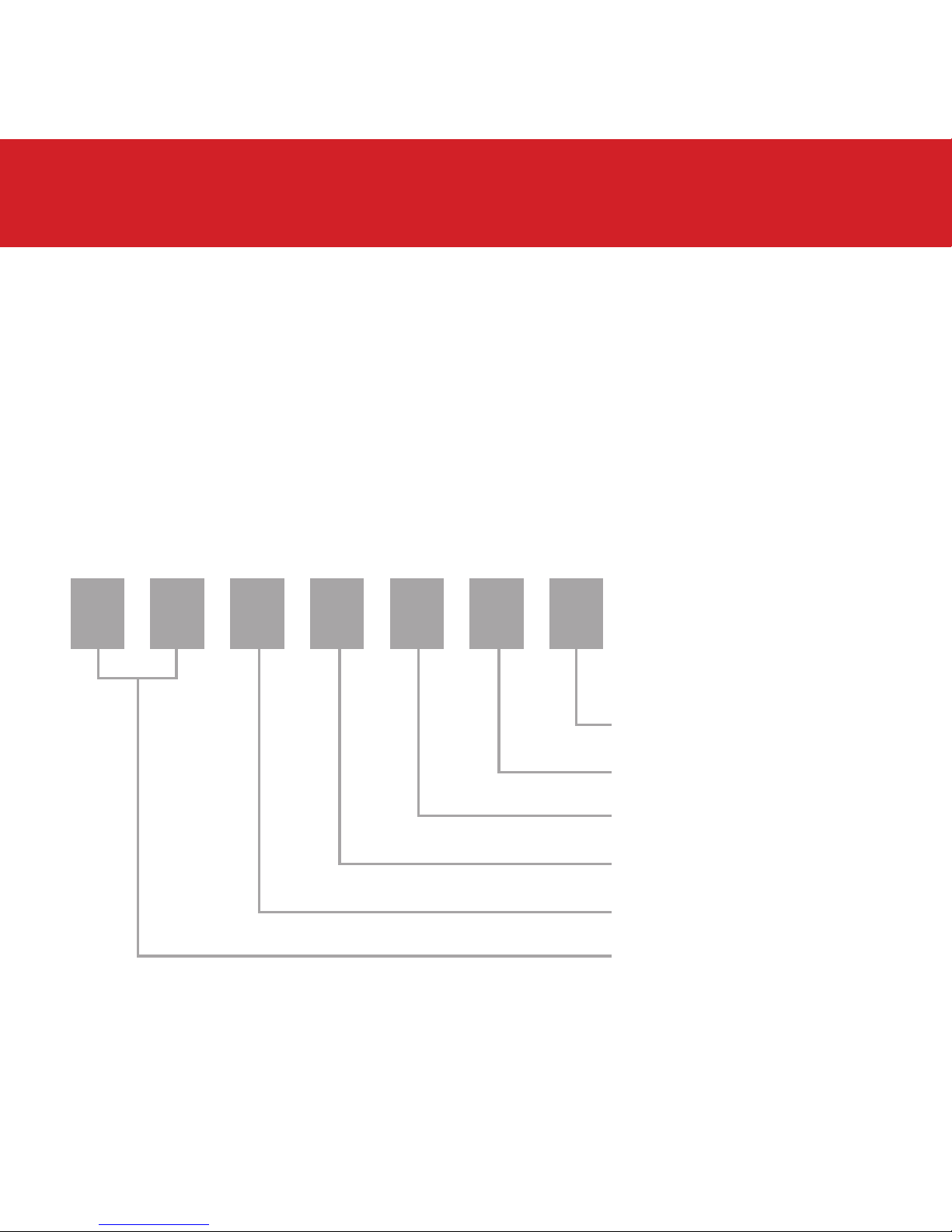
Installing your thermostat
230/240V AC Supply Live
230/240V AC Supply Neutral
UFH Neutral (Load N)
UFH Live (Load L)
Earth (Ground)
Sensor connections
(No polarity)
5. Wiring diagram
Connect the Thermostat to the underfloor
heating (UFH) cold tail, power supply and floor
temperature sensor.
The floor temperature sensor is not polarity sensitive.
7654321
11
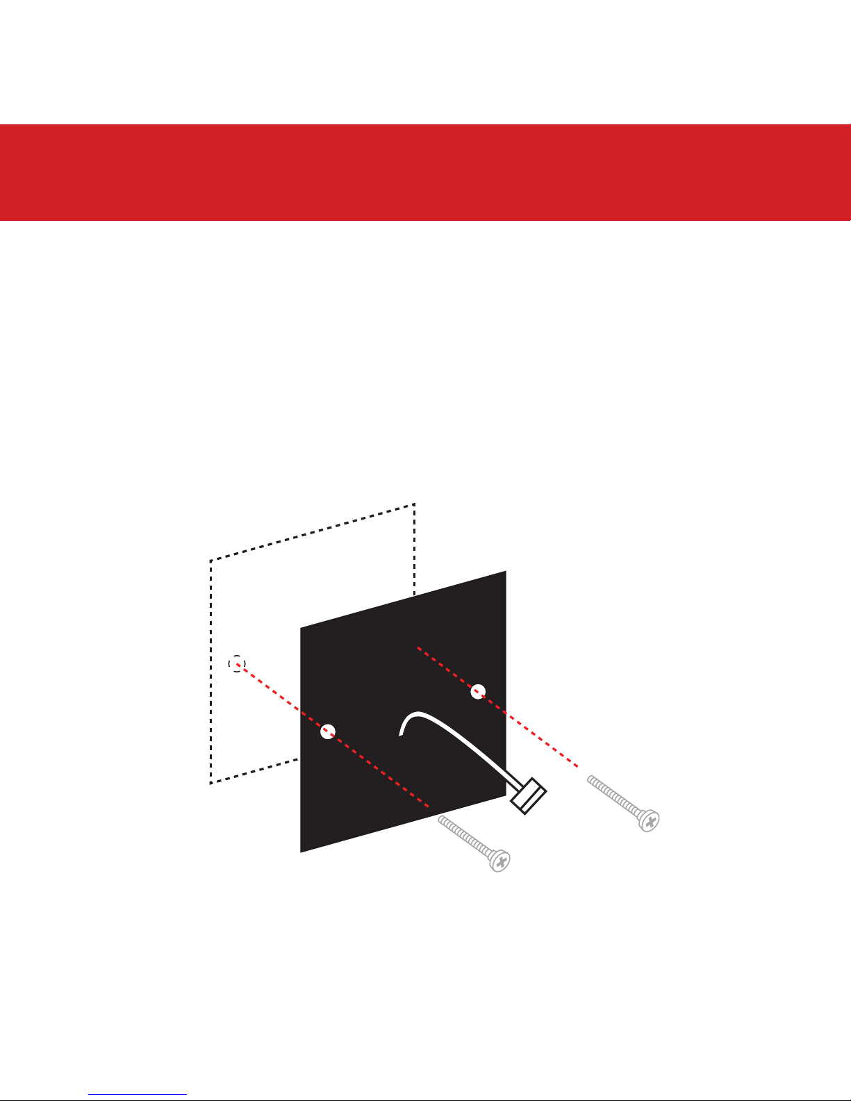
Installing your thermostat
6. Fix mounting plate in position
Use a cross-head screwdriver to fix the mounting plate to the
back box in the wall. Now you can connect the white ribbon
cable to the fascia.

12
Installing your thermostat
7. Fix thermostat fascia in place
Locate the thermostat onto the mounting plate and
push down to clip in place.
13
8. Switching on your system
It is important that all adhesives and
grouting is dry and fully cured before you
switch on your underfloor heating.
Most adhesives take between 7 to 10 days
to cure. Follow manufacturer guidelines.
The temperature of your underfloor heating
should be increased gradually to avoid
thermal shock in the floor. Start at 15°C and
work up to your desired temperature 2-3°C
per day.
Observe any maximum temperature
guidelines from your floor manufacturer.
Wait for
7 - 10 Days
before you
switch on
!
Installing your thermostat

14
Advanced Settings
Adjusting the settings
To access the settings, switch the unit off by
pressing .
Press and hold and together for 7 seconds.
Press to cycle between settings 01 to 12.
Use and to adjust the settings.
When you are finished, leave the thermostat idle
for 30 seconds. It will automatically save your
settings and switch off.
Switch the unit on by pressing to continue
using the thermostat with your new settings.

15
Advanced Settings
MENU DESCRIPTION RANGE DEFAULT
01 Temperature calibration -8°C ~ 8°C 0°C
02 Maximum set point 5°C ~ 80°C 35°C
03 Minimum set point 5°C ~ 80°C 5°C
04 Sensor mode IN (Ambient), OUT (Floor),
ALL (Ambient with floor limit) OUT
05 Frost protection 5°C ~ 15°C or - (Off) 5°C
06 Floor temperature display (ALL sensor mode only)
07 Temperature limit 10°C ~ 80°C (ALL mode only) 35°C
08 Status after power failure LA: On as before, OF: Off after
power failure LA
09 Software version 5215: 7021 V1.1
5216: 5101 V1.1
10 Factory reset rE (yes)
11 Backlight timer 10 secs - 300 secs (5 mins) 20s
12 Backlight brightness level 1 (min), 2, 3, 4 (max) 4

16
1
7
2
3
54 6
1. Measured temperature
2. Heating on icon
3. Lock icon
4. Up arrow
5. Power button
6. Down arrow
7. Set temperature
User interface

17
Technical data
Supply voltage 230V 50/60Hz
Maximum load 16A
Backup storage EEPROM
Temperature range 5 ~ 80°C (0.5°C increments)
Accuracy ±0.5°C
Sensor rating NTC 10kΩ@ 25°C
Consumption 2W
Warranty 3 years
IP rating IP30
Width 85mm
Height 85mm
Depth 46mm (31mm in wall)

18
Key lock
Locking the keys
To lock the keys press and hold and together for
7 seconds.
The icon will appear when the keys are locked and
the keys will not function.
To unlock the keys press and hold and together
for 7 seconds.
Factory reset
Find menu item 10 in the advanced settings (page 15).
Press and then . The thermostat will reset to factory
settings after 7 seconds. This will totally erase the time,
date, heating program and any adjusted settings.

19
Notes

Service and support
Thermogroup UK
Bridge House
Hop Pocket Lane
Paddock Wood
Kent TN12 6DQ
UNITED KINGDOM
0800 019 5899
01622 689 440
www.thermogroupuk.com
sales@thermogroupuk.com
Thermogroup EU
Pinnacle House
Newtown Cross
The Ward. Dublin 11
D11 K27C
Rep. of IRELAND
01 866 0584
www.thermogroupeu.com
sales@thermogroupeu.com
Thermogroup AU
Thermogroup Pty Ltd
PO Box 822
Leeton NSW 2705
AUSTRALIA
1300 368 631
www.thermogroup.com.au
sales@thermogroup.com.au
Watch the video guide on our website
www.thermogroupuk.com www.thermogroup.com.au
This manual suits for next models
1
Table of contents
Other thermotouch Thermostat manuals


