Derby LC-9 User manual

Print Instructions for Print Vendors (Paper Manuals)
OPERATOR’SMANUAL
TOTAL PAGE COUNT: Less than 45
Paper Size: • 11 x 17
• Body - 50 lbs brilliant white offset or equivalent.
• Cover - on 80 lbs coated cover stock
(NOTE: If total order quantity is less than 100 pieces, use uncoated cover stock)
Press: • Body - 1-color, 2-sided
• Cover - 1-color, 2-sided
Bindery: • Staple (2X), Face Trim
TOTAL PAGE COUNT: 45 or greater
Paper Size: • 8-1/2 x 11
• Body - 50 lbs brilliant white offset or equivalent.
• Cover - on 80 lbs coated cover stock
(NOTE: If total order quantity is less than 100 pieces, use uncoated cover stock)
Press: • Body - 1-color, 2-sided
• Cover - 1-color, 2-sided
Bindery: • Perfect Bind, Face Trim (3 knife)
GENERAL
COVERS: • Covers are located at the beginning of this package.
• Back cover is the page IMMEDIATELY AFTER the front cover.
• Check the front cover for the individual part number (typically a 2xxxx or 182xxxx number).
• Check the front cover for the document number (TP 1xx - xxxx - xx - xx - xx)
BODY: •ODD number pages are ALWAYS right hand pages, and EVEN number are ALWAYS left hand
pages.
General: • This instruction page is NOT part of the manual and must NOT be printed.
• Pages labeled with the text “THIS PAGE INTENTIONALLY BLANK” are placement pages ONLY,
and should NOT be printed.
If you have any further questions regarding this manual, please contact Ken Cehonski in
Ferris Industries Engineering Department at (315) 495-0100 ext. 249.

THIS PAGE INTENTIONALLY BLANK

TM
OPERATOR’S
MANUAL
1822408
5/2000
TP 100-7009-00-SL-D
The Stallion
Zero-Turn Riding Mower
Model:
ZT2354
mowers are built by
Ferris Industries, a
Simplicity company.
Ferris Industries
5375 North Main Street
Munnsville, NY 13409
800-933-6175
TM

Ferris Industries
5375 North Main Street
Munnsville, NY 13409
800-933-6175
www.ferrisindustries.com
© Copyright 2000 Ferris Industries
All Rights Reserved. Printed in USA.

1
WARNING
Engine exhaust from this product contains
chemicals known, in certain quantities, to cause
cancer, birth defects, or other reproductive harm.
Table of Contents
Identification Numbers .......................................2
Safety Rules & Information ................................3
Features & Controls............................................6
Control Functions....................................................6
Safety Interlock System ..........................................7
Operating the Tractor..........................................8
General ...................................................................8
Checks Before Starting...........................................8
Starting the Engine .................................................9
Stopping the Rider ..................................................9
Mowing....................................................................9
Pushing the Rider by Hand.....................................9
Zero Turn Driving Practice ....................................10
Mower Removal & Installation ..............................12
Storage .................................................................14
Starting After Long Term Storage .........................14
Regular Maintenance ........................................16
Maintenance Schedule .........................................16
Checking Tire Pressures.......................................16
Checking/Adding Fuel...........................................17
Fuel Filter ..............................................................17
Oil & Filter Change ...............................................17
Check / Change Air FIlter .....................................17
Check Hydraulic Oil Level.....................................17
Lubrication ............................................................18
Battery Maintenance .............................................20
Checking Battery Fluid..................................20
Cleaning the Battery and Cables..................20
Servicing the Mower Blades .................................21
Troubleshooting, Adjustments & Service .......23
Troubleshooting the Tractor ..................................23
Troubleshooting the Mower ..................................24
Seat Adjustment....................................................25
Ground Speed Control Lever Adjustment.............25
Speed Balancing Adjustment................................25
Parking Brake Adjustment ....................................26
Suspension Height Adjustment.............................26
PTO Clutch Adjustment.........................................27
Blade Brake Check ...............................................27
Neutral Adjustment................................................28
Dampener and Return Spring Adjustment............28
Mower Adjustments...............................................29
Gauge Wheel Adjustment .............................29
Cutting Height Adjustment ............................29
Deck Roller Adjustment ................................29
Hydraulic Pump Drive Belt Replacement .............30
Mower Belt Replacement......................................30
Battery Service......................................................32
Checking the Battery Voltage ...........................32
Charging A Completely
Discharged Battery .......................................32
Jump Starting with
Auxiliary (Booster) Battery ............................32
Lawn Care & Mowing Information.............LC—1
International Symbols ................................LC—8
Technical Manuals ......................................LC—8
NOTE: In this manual, “left” and “right” are referred to as
seen from the operating position.
© Copyright 2000 Ferris Industries
All Rights Reserved. Printed in USA.
TP 100-7009-00-SL-D

2
IDENTIFICATION TAG LOCATIONS
Identification
Numbers
When contacting your
Authorized Dealer for
replacement parts, service,
or information YOU MUST
HAVE THESE NUMBERS.
IDENTIFICATION NUMBERS
Record your model name/number, unit and mower deck
manufacturer numbers and engine serial number in the
space provided for easy reference.
• The Tractor I.D. tag is located on the inside of the
main frame rail, behind the deck height plate.
• For location of Engine Serial Number, refer to the
Engine Owner’s Manual.
Be sure to fill out and return the Warranty Registration
Card supplied with your unit. ENGINE REFERENCE DATA
Model Description Name/Number
Unit MFG Number
PRODUCT REFERENCE DATA
Unit SERIAL Number
Dealer Name Date Purchased
Engine Make/Model Engine ID/Serial Number
Mower Deck MFG Number Mower Deck SERIAL Number
Tractor
identification tag
XXXXXXX XXXXXXX
N/A N/A

3
Read these safety rules and follow them closely. Failure to obey these rules could result in loss of con-
trol of unit, severe personal injury or death to you, or bystanders, or damage to property or equipment.
This mowing deck is capable of amputating hands and feet and throwing objects. The triangle
in text signifies important cautions or warnings which must be followed.
Safety Rules
& Information
WARNING
Never operate on slopes greater than 30 percent
(16.7°) which is a rise of three feet vertically in 10
feet horizontally.
Select slow ground speed before driving onto slope.
In addition to front and rear weights, use extra caution
when operating on slopes with rear-mounted grass
catcher.
Mow UP and DOWN the slope, never across the
face, use caution when changing directions and
DO NOT START OR STOP ON SLOPE.
Do
• See your authorized dealer for recommendations of
available weights to improve stability.
• Mow up and down slopes, not across.
• Remove obstacles such as rocks, tree limbs, etc.
• Watch for holes, ruts, or bumps. Uneven terrain
could overturn the unit. Tall grass can hide obstacles.
• Use slow speed. Choose a slow speed so that you
will not have to stop or change speed while on the
slope.
• Use extra care with grass catchers or other attach-
ments. These can change the stability of the unit.
• Keep all movement on the slopes slow and gradual.
Do not make sudden changes in speed or direction.
Do Not
•Do not start or stop on a slope. If tires lose traction,
disengage the blade(s) and proceed slowly straight
down the slope.
•Do not turn on slopes unless necessary, and then,
turn slowly and gradually downhill, if possible.
•Do not mow near drop-offs, ditches, or embank-
ments. The mower could suddenly turn over if a
wheel is over the edge of a cliff or ditch, or if an edge
caves in.
•Do not mow on wet grass. Reduced traction could
cause sliding.
•Do not try to stabilize the unit by putting your foot on
the ground.
•Do not use grass catcher on steep slopes.
GENERAL OPERATION
• Read, understand, and follow all instructions in the
manual and on the unit before starting.
• Only allow responsible adults, who are familiar with
the instructions, to operate the unit.
• Clear the area of objects such as rocks, toys, wire,
etc., which could be picked up and thrown by the
blade(s).
• Be sure the area is clear of other people before
mowing. Stop unit if anyone enters the area.
• Never carry passengers.
• Do not mow in reverse unless absolutely necessary.
Always look down and behind before and while trav-
elling in reverse.
• Be aware of the mower discharge direction and do
not point it at anyone. Do not operate the mower
without either the entire grass catcher or the deflec-
tor in place.
• Slow down before turning.
• Never leave a running unit unattended. Always
disengage the PTO, set parking brake, stop engine,
and remove keys before dismounting.
• Turn off the PTO switch to disengage the blades
when not mowing.
• Stop engine before removing grass catcher or
unclogging chute.
• Mow only in daylight or good artificial light.
• Do not operate the unit while under the influence of
alcohol or drugs.
• Watch for traffic when operating near or crossing
roadways.
• Use extra care when loading or unloading the unit
into a trailer or truck.
• Data indicates that operators, age 60 years and
above, are involved in a large percentage of riding
mower-related injuries. These operators should
evaluate their ability to operate the riding mower
safely enough to protect themselves and others from
serious injury.
SLOPE OPERATION
Slopes are a major factor related to loss-of-control and
tip-over accidents, which can result in severe injury or
death. All slopes require extra caution. If you cannot
back up the slope or if you feel uneasy on it, do not
drive on it.

4
Safety Rules & Information
CHILDREN
Tragic accidents can occur if the operator is not alert to
the presence of children. Children are often attracted to
the unit and the mowing activity. Never assume that chil-
dren will remain where you last saw them.
• Keep children out of the mowing area and under the
watchful care of another responsible adult.
• Be alert and turn unit off if children enter the area.
• Before and during reverse operation, look behind
and down for small children.
• Never carry children. They may fall off and be seri-
ously injured or interfere with safe unit operation.
• Never allow children to operate the unit.
•
Use extra care when approaching blind corners, shrubs,
trees, or other objects that may obscure vision.
TRANSPORTING AND STORAGE
• Always observe safe refueling and fuel handling
practices when refueling the unit after transportation
or storage.
• Always follow the engine manual instructions for
storage preparations before storing the unit for both
short and long term periods.
• Always follow the engine manual instructions for
proper start-up procedures when returning the unit to
service.
• Never store the unit or fuel container inside where
there is an open flame or pilot light, such as in a
water heater. Allow unit to cool before storing.
SERVICE AND MAINTENANCE
• Use extra care when handling gasoline and other
fuels. They are flammable and vapors are explosive.
a) Use only an approved container.
b) Never remove fuel cap or add fuel with the engine
running. Allow engine to cool before refueling. Do
not smoke.
c) Never refuel the unit indoors.
• Never run a unit in an enclosed area.
• Keep nuts and bolts, especially blade attachment
bolts, tight and keep equipment in good condition.
• Never tamper with safety devices. Check their proper
operation regularly.
• Keep unit free of grass, leaves, or other debris build-
up. Clean up oil or fuel spillage.
• Stop and inspect the equipment if you strike an
object. Repair, if necessary, before restarting.
• Never make adjustments or repairs with the engine
running unless specified otherwise in the engine
manufacturer’s manual.
• Grass catcher components are subject to wear, dam-
age, and deterioration, which could expose moving
parts or allow objects to be thrown. Frequently check
components and replace with manufacturer’s recom-
mended parts, when necessary.
• Mower blades are sharp and can cut. Wrap the
blade(s) or wear gloves, and use extra caution when
servicing them.
• Check brake operation frequently. Adjust and service
as required.
• Use only factory authorized replacement parts when
making repairs.
• Always comply with factory specifications on all
settings and adjustments.
• Only authorized service locations should be utilized
for major service and repair requirements.
• Never attempt to make major repairs on this unit
unless you have been properly trained. Improper
service procedures can result in hazardous opera-
tion, equipment damage and voiding of manufactur-
er’s warranty.

5
SAFETY DECALS
This unit has been designed and manufactured to pro-
vide you with the safety and reliability you would expect
from an industry leader in outdoor power equipment
manufacturing.
Although reading this manual and the safety instructions
it contains will provide you with the necessary basic
knowledge to operate this equipment safely and effec-
tively, we have placed several safety labels on the unit
to remind you of this important information while you are
operating your unit.
All DANGER, WARNING, CAUTION and instructional
messages on your rider and mower should be carefully
read and obeyed. Personal bodily injury can result when
these instructions are not followed. The information is for
your safety and it is important! The safety decals below
are on your rider and mower.
If any of these decals are lost or damaged, replace them
at once. See your local dealer for replacements.
These labels are easily applied and will act as a con-
stant visual reminder to you, and others who may use
the equipment, to follow the safety instructions neces-
sary for safe, effective operation.
ROTATING PARTS UNDER ENGINE.
KEEP HANDS AND FEET CLEAR.
STOP ENGINE BEFORE SERVICING.
DANGER
DANGER
ROTATING CUTTING BLADE
Do not put hands or feet
under mower deck while
blade is rotating.
1704276
DANGER
ROTATING CUTTING BLADE
Do not operate mower
without deflector or entire
grass catcher in place.
1704277
Safety Rules & Information
Decal - Danger
Part No. 1704276
Decal - Danger
Part No. 1704277
Decal - Danger
Part No. 22143
Decal - Warning/Danger
Part No. 45560
Decal - Operation & Controls
Part No. 45559
OPERATION
To Start Engine:
To Stop Engine:
Seat must be occupied, PTO
Switch OFF, Parking Brake ON
and both control handles are
locked in Neutral.
Engage Parking Brake, Throttle at
half to full, turn Ignition Switch Off.
Before Leaving Machine:
Turn PTO switch off, shut off engine,
remove key, and set Parking
Brake
To Operate PTO Clutch:
Operator must be in seat.
Pull up to Engage.
Push down to Disengage.
When Operator Leaves Seat:
Engine will shut off if PTO is on.
Engine will shut off of Parking Brake
is off.
Engine will shut off if both control
levers are not locked in neutral.
GROUND SPEED AND
STEERING LEVERS
Right lever controls speed
and direction of right drive
wheel. Notch is neutral
lock.
Left lever controls speed and
direction of left drive wheel.
Notch is neutral lock.
Steer by slowing the lever in
the direction of the turn.
PARKING BRAKE
LEVER
Pull to set Parking Brake.
Push to release Parking
Brake.
DECK LIFT PEDAL
Push to raise deck.
CUTTING HEIGHT
ADJUSTMENT PIN
DO NOTTOW!
Damage may result to
HydrostaticTransmission.
6
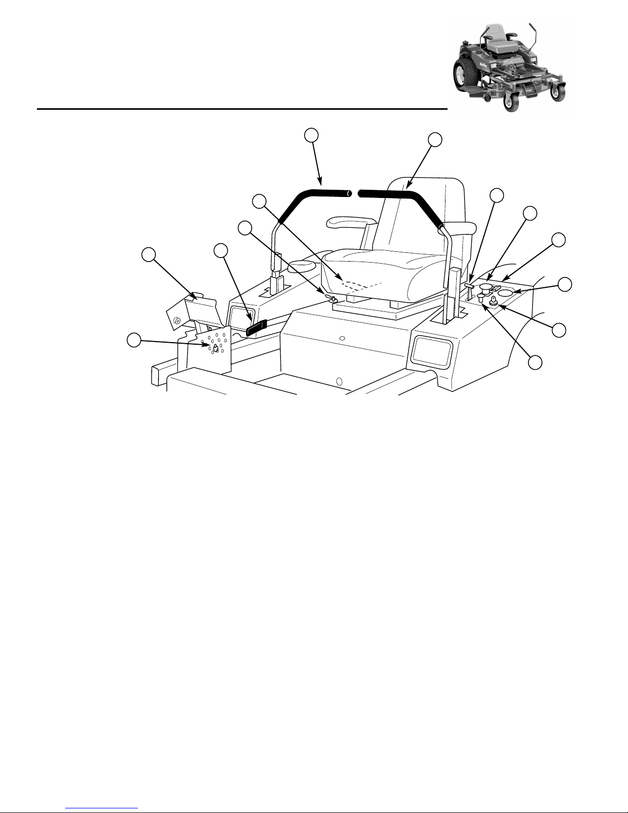
Features & Controls
of the Zero Turn Rider
CONTROL FUNCTIONS
The information below briefly describes the function of individual controls. Starting, stopping, driving, and mowing
require the combined use of several controls applied in specific sequences. To learn what combination and
sequence of controls to use for various tasks see the OPERATION section.
A. Ground Speed Control Levers
These levers control the ground speed of the rider. The
left lever controls the left rear drive wheel and the right
controls the right rear drive wheel.
Moving a lever forward increases the FORWARD speed
of the associated wheel, and pulling back on a lever
increases the REVERSE speed.
Note: The further a lever is moved away from the neutral
position the faster the drive wheel will turn.
See the Operating the Zero Turn Rider section for steer-
ing instructions.
B. Seat Adjustment Lever
The seat can be adjusted forward and back. Move the
lever forward, position the seat as desired, and release
the lever to lock the seat in position.
C. Ignition Switch
The ignition switch starts and stops the engine, it has
three positions:
OFF Stops the engine and shuts off the
electrical system.
RUN Allows the engine to run and powers the
electrical system.
START Cranks the engine for starting.
NOTE: Never leave the ignition switch in the RUN posi-
tion with the engine stopped–this drains the battery.
Please take a moment and familiarize
yourself with the name, location, and
function of these controls so that you will
better understand the safety and operating
instructions provided in this manual.
H
J
AA
B
G
D
F
C
K
I
E
Figure 1. Control Locations
L

7
Features & Controls
D. Parking Brake Handle
The parking brake is applied by pulling UP on the park-
ing brake handle until it locks over-center. To release the
parking brake, push the handle DOWN.
E. PTO (Power Take Off) Switch
The PTO switch engages and disengages the mower.
Pull UP on the switch to engage, and push DOWN to
disengage.
F & G. Deck Lift Pedal & Cutting Height
Adjustment Pin
These control the cutting height of the mower deck.
Depress the pedal until it locks into the TRANSPORT
position. Place the adjustment pin in the desired cutting
height and release the lift pedal.
H & I. Throttle / Choke Control
Pulling the round choke control knob (I) out fully chokes
the engine for cold starts. (A warm engine may not
require choking.) Moving the throttle control (H) fully for-
ward is FULL throttle position. Always operate the unit
at FULL throttle when mowing.
J. Headlight Switch
Turn the switch ON to light the front headlight.
K. Hour Meter
Measures the time of the PTO being engaged.
L. Fuel Shut Off Valve
Turning the handle to the desired position determines
which tank will be supplying fuel. With the handle point-
ing forward, it will draw fuel from the left-hand tank.
With the handle pointed towards the rear, it will draw fuel
from the right-hand fuel tank. With the handle pointing
towards the right, it will shut off fuel flow to the engine.
SAFETY
INTERLOCK SYSTEM
This unit is equipped with safety interlock switches and
other safety devices. These safety systems are present
for your safety, do not attempt to bypass safety switch-
es, and never tamper with safety devices. Check their
operation regularly.
Operational SAFETY Checks
Your unit is equipped with a seat switch safety system.
Check the seat switch operation every fall and spring
with the following tests.
Test 1 — Engine should NOT crank if:
• PTO switch is engaged, OR
• Parking brake is not engaged, OR
• Motion control handles are not in the NEUTRAL
position, OR
• Operator is not on the seat.
Test 2 — Engine SHOULD crank if:
• PTO switch is NOT engaged, AND
• Parking brake is engaged, AND
• Motion control handles are locked in the NEUTRAL
position, AND
• Operator is on the seat.
Test 3 — Engine should SHUT OFF if:
• Operator rises off seat with PTO engaged, OR
• Operator rises off seat with parking brake disen-
gaged.
Test 4 — Blade Brake Check
Mower blades and mower drive belt should come to a
complete stop within five seconds after electric PTO
switch is turned off (or operator rises off seat). If mower
drive belt does not stop within five seconds, see your
dealer.
NOTE: Once the engine has stopped, PTO switch must
be turned off, parking brake must be engaged, and the
motion control handles must be locked in the NEUTRAL
position after the operator returns to the seat in order to
start the engine.
WARNING
If the unit does not pass a safety test, do
not operate it. See your authorized dealer. Under
no circumstance should you attempt to defeat
the purpose of the safety interlock system.
Operating
the Zero Turn Rider
GENERAL OPERATING SAFETY
Before first time operation:
• Be sure to read all information in the Safety and
Operation sections before attempting to operate this
tractor and mower.
• Become familiar with all of the controls and how to
stop the unit.
• Drive in an open area without mowing to become
accustomed to the unit.brake pedal or set the park-
ing brake.
CHECKS BEFORE STARTING
• Check that crankcase is filled to full mark on dipstick.
See the engine Operator’s Manual for instructions
and oil recommendations.
• Make sure all nuts, bolts, screws and pins are in
place and tight.
• Adjust the seat position, and make certain you can
reach all controls from operator’s position.
• Fill the fuel tank with fresh fuel. Refer to engine man-
ual for fuel recommendations.
WARNING
Never allow passengers to ride on the unit.
Before leaving the operator’s position for any
reason, engage the parking brake, disengage the
PTO, stop the engine and remove the key.
To reduce fire hazard, keep the engine, tractor
and mower free of grass, leaves and excess
grease. Do not stop or park tractor over dry
leaves, grass or combustible materials.
Gasoline is highly flammable and must be
handled with care. Never fill the tank when the
engine is still hot from recent operation. Do not
allow open flame, smoking or matches in the
area. Avoid over-filling and wipe up any spills.
DANGER
OPERATING ON SLOPES
CAN BE DANGEROUS
Never operate on slopes greater than 30 percent
(16.7°) which is a rise of three feet vertically in 10
feet horizontally.
Operate the unit at a slow ground speed when
driving onto slope.
In addition to counterweights, use extra caution
when operating on slopes with rear-mounted
grass catcher. Mow UP and DOWN the slope,
never across the face, use caution when
changing directions and DO NOT START OR
STOP ON SLOPE.
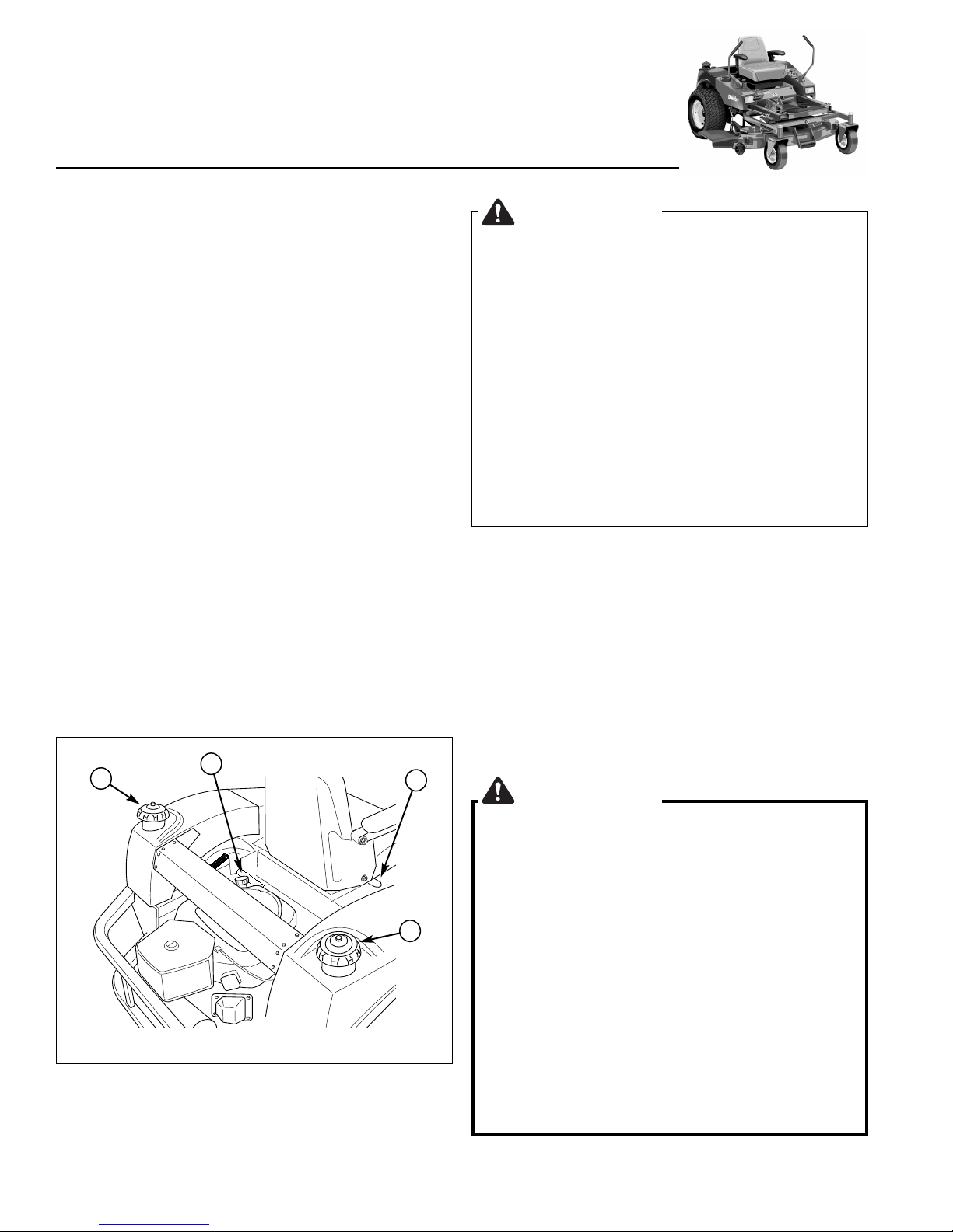
A
B
C
A
Figure 2. Pre-start Checks
A. Fuel Tank Filler Neck
B. Crankcase Oil Fill
C. Seat Adjustment Lever
8

WARNING
If you do not understand how a specific control
functions, or have not yet thoroughly read the
FEATURES & CONTROLS section, do so now.
Do NOT attempt to operate the tractor without
first becoming familiar with the location and
function of ALL controls.
STARTING THE ENGINE
1. While sitting in the operator’s seat, engage the park-
ing brake and make sure the PTO switch is disen-
gaged and the motion control handles are locked in
the NEUTRAL position.
2. NOTE: A warm engine may not require choking.
Set the engine throttle control (H, Figure 1) to FAST
throttle position. Then fully close the choke (I, Figure
1) by pulling the knob OUT fully.
3. Insert the key into the ignition switch (K, Figure 1)
and turn it to START.
4. After the engine starts, gradually open the choke
(push knob down fully).
Warm up the engine by running it for at least a minute
before engaging the PTO switch or driving the rider.
5. After warming the engine, ALWAYS operate the
unit at FULL THROTTLE when mowing.
In the event of an emergency the engine can be
stopped by simply turning the ignition switch to
STOP. Use this method only in emergency situations.
For normal engine shut down follow the procedure given
in STOPPING THE RIDER.
STOPPING THE RIDER
1. Returning the ground speed control levers (A, Figure
1) to the middle position will stop tractor movement.
Pivot the levers outward and lock them in NEUTRAL.
2. Disengage the PTO by pushing down on the PTO
switch (E, Figure 1).
3. Engage the parking brake by pulling the handle (D,
Figure 1) up until it locks into position.
4. Move the throttle control (H, Figure 1) to mid-throttle
position and turn the ignition key to OFF Remove
the key.
MOWING
1. Engage the parking brake. Make sure the PTO
switch is disengaged, the motion control handles are
locked in the NEUTRAL position and the operator is
on the seat.
2. Start the engine (see STARTING THE ENGINE).
3. Set the mower cutting height.
4. Set the throttle to FULL.
5. Engage the PTO by pulling up on the PTO switch (E,
Figure 1).
6. Begin mowing. See Section C for tips on mowing
patterns, lawn care, and trouble shooting information.
7. When finished, shut off the PTO.
8. Stop the engine (see STOPPING THE TRACTOR
AND ENGINE).
PUSHING THE RIDER BY HAND
1. Disengage the PTO, engage the parking brake, turn
the ignition OFF, and remove the key.
2. Lift the seat plate to gain access to the battery com-
partment and hydraulic pumps.
3. To disengage the pumps (free-wheel position), turn
the hydraulic release valves (A, Figure 3) located on
the pumps COUNTER-CLOCKWISE a maximum of
2 full turns.
4. Disengage the parking brake.
The tractor can now be pushed by hand.
5. After moving the tractor, re-engage the pumps (drive
position) by turning the release valves CLOCKWISE
and tighten to 80-120 in. lbs. of torque.
DO NOT TOW RIDER
Towing the unit will cause hydraulic pump
and wheel motor damage. Do not use
another vehicle to push or pull this unit.
Operating the Zero Turn Rider
Figure 3. Hydraulic System By-Pass
A. Hydraulic Release Valve
A
9

10
Operating the Zero Turn Rider
ZERO TURN
DRIVING PRACTICE
The lever controls of the Zero Turn rider are responsive,
and learning to gain a smooth and efficient control of the
rider’s forward, reverse, and turning movements will take
some practice.
Spending some time going through the maneuvers
shown and becoming familiar with how the unit acceler-
ates, travels, and steers — before you begin mowing —
is absolutely essential to getting the most out of the Zero
Turn rider.
Locate a smooth, flat area of your lawn — one with
plenty of room to maneuver. (Clear the area of
objects, people and animals before you begin.) Operate
the unit at mid-throttle during this practice session
(ALWAYS operate at full throttle when mowing), and turn
slowly to prevent tire slippage and damage to your lawn.
We suggest you begin with the Smooth Travel proce-
dure to the right, and then advance through the forward,
reverse, and turning maneuvers.
You must release the parking brake prior to moving the
control levers inward.
BASIC DRIVING
Forward Travel Practice
Gradually move both ground speed control levers —
evenly FORWARD from neutral. Slow down and repeat.
NOTE: Straight forward travel takes practice. If neces-
sary, top speed can be balance-adjusted — see the
Speed Balancing Adjustment in the Adjustments section
near the back of this manual.
Reverse Travel Practice
LOOK DOWN & BEHIND, then gradually move both
ground speed control levers evenly BACK from neutral.
Slow down and repeat.
NOTE: Practice backing up for several minutes before
attempting to do so near objects. The rider turns sharply
in reverse as well as forward, and backing up straight
takes practice.
Figure 5. Forward Travel
Forward
Travel
Figure 6. Forward Travel
Reverse
Travel
Smooth Travel
The lever controls of the
Zero Turn rider are
RESPONSIVE .
The BEST method of
handling the ground
speed control levers is in
three steps — as shown
in Figure 4.
FIRST place your hands
onto the levers as shown.
SECOND, to go forward
gradually push the levers
forward with your palms.
THIRD, to speed up
move the levers farther
forward. To slow down
smoothly, slowly move
the levers toward neutral.
Figure 4. Move Control
Levers Gradually

11
ADVANCED DRIVING
Executing an End-Of-Row Zero
Turn
Your Zero Turn Rider’s unique ability to turn
in place allows you to turn around at the end
of a cutting row rather than having to stop
and Y-turn before starting a new row.
For example, to execute a right end-of row
Zero Turn:
1. Slow down at the end of the row.
2. Move the LEFT ground speed control
lever forward slightly while moving the
RIGHT ground speed control lever back
to center and then slightly back from cen-
ter.
3. Begin mowing forward again.
This technique turns the rider RIGHT and
slightly overlaps the row just cut —eliminating
the need to back up and re-cut missed grass.
As you become more familiar and experi-
enced with operating the Zero Turn rider, you
will learn more maneuvers that will make
your mowing time easier and more enjoy-
able.
Remember, the more you practice, the better
your control of the Zero Turn will be!
Operating the Zero Turn Rider
Practice Turning In Place
To turn in place, “Zero Turn,” gradually move one ground
speed control lever forward from neutral and one lever
back from neutral simultaneously. Repeat several times.
NOTE: Changing the amount each lever is pulled—for-
ward or back, changes the “pivot point” you turn on.
Practice Turning Around a Corner
While traveling forward allow one handle to gradually
return back toward neutral. Repeat several times.
NOTE: To prevent pivoting directly on the tire tread, it is
best to keep both wheels going at least slightly forward.
Executing
Turns
Figure 7. Turning Around a Corner Figure 8. Turning in Place
Turning
In-Place
Figure 9. Executing an End-Of-Row Turn
12
Operating the Zero Turn Rider
MOWER DECK REMOVAL &
INSTALLATION
Removing the Mower Deck
NOTE: Perform mower removal on a hard, level surface
such as a concrete floor.
1. Push the deck lift pedal forward until it locks in the
“TRANSPORT” position and remove the height
adjustment pin.
2. Place two, 2” x 4” blocks (B, Figure 10) under the
outside edges of the mower.
3. Release the deck lift pedal to lower the deck.
4. Dismount the mower and push back on the deck lift
pedal until the mower chains are slack. Reinstall the
height adjustment pin in any hole to prevent the
pedal from pivoting forward and applying tension to
the chains.
5. Remove the hairpin clip and clevis pin and remove
the deck lift foot pedal.
6. Remove the hairpin clip, push down on the top of the
spindle, and rotate the gauge wheel (A, Figure 10)
into sliding position. Replace the hair pin clip.
7. Lift the floor plate to gain access to the deck drive
belt.
8. Release the spring tension on the deck drive belt
with a wrench on top of the idler pulley (A, Figure
11). Slide the drive belt over the edge of the idler
pulley to remove the belt. Remove the belt from the
PTO clutch pulley groove before proceeding.
NOTE: Releasing the belt tension may loosen the hard-
ware fastening the idler pulley to the idler arm. Make
sure to re-tighten the hardware if this occurs.
9. Remove the chain mounting hardware from the lift
arm end of the chain (B, Figure 12).
10. Remove the hardware fastening the roller position
link (D, Figure 12) from the pusher bar end.
11. Remove the 2” x 4” blocks from under the mower.
12. Remove the rear deck mount pins (C, Figure 12) and
let the pusher bar (A, Figure 12) swing out of the
way.
13. Slide the mower out from under tractor.
WARNING
Engage parking brake, disengage PTO, stop
engine and remove key before attempting to
install or remove the mower.
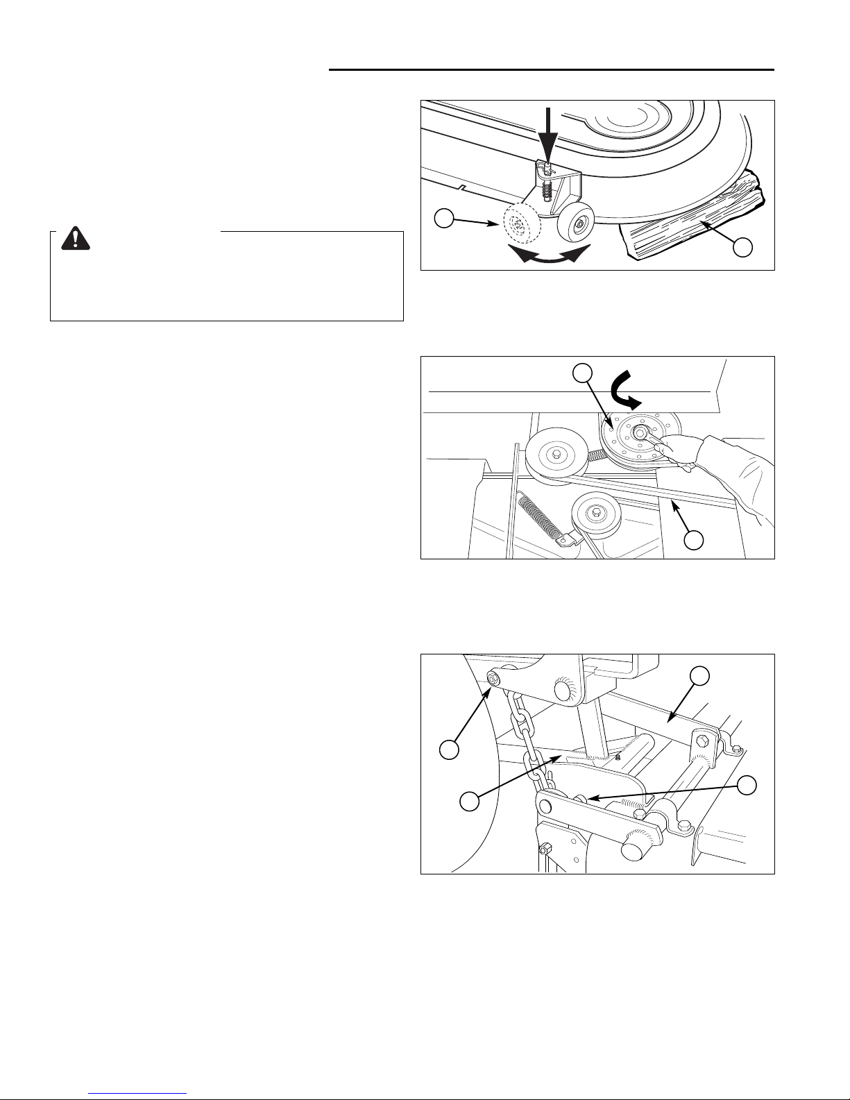
Figure 10. Gauge Wheels
A. Gauge Wheel
B. 2” x 4” Block
Figure 12. Rear Deck Mount (right side shown)
A. Pusher Bar(s) C. Bar Mount Pin(s)
B. Chain Mount Hardware D. Roller Position Link
(all locations) (right side only)
D
A
B
C
Figure 11. Mower PTO Belt
A. Idler Pulley (Flat-sided)
B. PTO Drive Belt
B
A
A
B

13
Operating the Zero Turn Rider
Installing the Mower Deck
NOTE: Perform mower installation on a hard, level sur-
face such as a concrete floor.
1. Slide the mower under the tractor.
2. Install the bar mount pins (C, Figure 12) to secure
the pusher bars (A, Figure 12) to the mower.
3. Place two, 2” x 4” blocks (B, Figure 10) under the
outside edges of the mower.
4. Install the roller position link (D, Figure 12) to the
pusher bar.
5. From the front of the machine, push back on the
deck lift pedal until it stops. Reinstall the height
adjustment pin in any hole to prevent the pedal from
pivoting forward.
5. Remove the hairpin clip and clevis pin and remove
the deck lift foot pedal.
7. Lift the floor plate to gain access to the deck drive
belt.
8. Secure the chains to the lift arms (B, Figure 12).
9. Install the drive belt on the PTO pulley, the arbor pul-
ley and V-sided idler pulley. Release the spring ten-
sion on the idler pulley (A, Figure 11) and install the
belt onto the pulley. Make sure the V-side of the belt
runs in the pulley grooves (Figure 13).
NOTE: Releasing the belt tension may loosen the hard
ware fastening the idler pulley to the idler arm. Make
sure to re-tighten the hardware if this occurs.
10. Remove the 2” x 4” blocks from under the mower.
11. Lower the floor plate and reinstall the deck lift foot
pedal with the hairpin clip and clevis pin.
WARNING
Engage parking brake, disengage PTO, stop
engine and remove key before attempting to
install or remove the mower.
FRONT
Figure 13. Mower PTO Belt Routing
A. Arbor Pulley C. Idler Pulley (Flat-sided)
B. PTO Drive Belt D. Idler Pulley (V-sided)
C
B
D
A

14
Operating the Zero Turn Rider
STORAGE
Temporary Storage (30 Days Or Less)
Remember, the fuel tank will still contain some gasoline, so
never store the unit indoors or in any other area where fuel
vapor could travel to any ignition source. Fuel vapor is also
toxic if inhaled, so never store the unit in any structure
used for human or animal habitation.
Here is a checklist of things to do when storing your unit
temporarily or in between uses:
• Keep the unit in an area away from where children may
come into contact with it. If there’s any chance of unau-
thorized use, remove the spark plug (s) and put in a
safe place. Be sure the spark plug opening is protected
from foreign objects with a suitable cover.
• If the unit can’t be stored on a reasonable level surface,
chock the wheels.
• Clean all grass and dirt from the mower.
Long Term Storage (Longer Than 30 Days)
Before you store your unit for the off-season, read the
Maintenance and Storage instructions in the Safety Rules
section, then perform the following steps:
1. Drain crankcase oil while engine is hot and refill with a
grade of oil that will be required when unit is used
again.
2. Prepare the mower deck for storage as follows:
a. Remove mower deck from the unit.
b. Clean underside of mower deck.
c. Coat all bare metal surfaces with paint or light coat of
oil to prevent rusting.
3. Clean external surfaces and engine.
4. Prepare engine for storage. See engine owner’s
manual.
5. Clean any dirt or grass from cylinder head cooling fins,
engine housing and air cleaner element.
6. Cover air cleaner and exhaust outlet tightly with plastic
or other waterproof material to keep out moisture, dirt
and insects.
7. Completely grease and oil unit as outlined in the
Normal Care section.
8. Clean up unit and apply paint or rust preventative to
any areas where paint is chipped or damaged.
9. Be sure the battery is filled to the proper level with
water and is fully charged. Battery life will be increased
if it is removed, put in a cool, dry place and fully
charged about once a month. If battery is left in unit,
disconnect the negative cable.
WARNING
Never store the unit, with gasoline in engine or
fuel tank, in a heated shelter or in enclosed,
poorly ventilated enclosures. Gasoline fumes may
reach an open flame, spark or pilot light (such as
a furnace, water heater, clothes dryer, etc.) and
cause an explosion.
Handle gasoline carefully. It is highly flammable
and careless use could result in serious fire
damage to your person or property.
Drain fuel into an approved container outdoors
away from open flame or sparks.
10. Drain fuel system completely or add a gasoline stabiliz-
er to the fuel system. If you have chosen to use a fuel
stabilizer and have not drained the fuel system, follow
all safety instructions and storage precautions in this
manual to prevent the possibility of fire from the ignition
of gasoline fumes. Remember, gasoline fumes can trav-
el to distant sources of ignition and ignite, causing risk
of explosion and fire.
NOTE: Gasoline, if permitted to stand unused for extended
periods (30 days or more), may develop gummy deposits
which can adversely affect the engine carburetor and cause
engine malfunction. To avoid this condition, add a gasoline
stabilizer to the fuel tank and run the engine a few minutes,
or drain all fuel from the unit before placing it in storage.
STARTING AFTER
LONG TERM STORAGE
Before starting the unit after it has been stored for a long
period of time, perform the following steps.
1. Remove any blocks from under the unit.
2. Install the battery if it was removed.
3. Unplug the exhaust outlet and air cleaner.
4. Fill the fuel tank with fresh gasoline. See engine
manual for recommendations.
5. See engine owner’s manual and follow all instructions
for preparing engine after storage.
6. Check crankcase oil level and add proper oil if
necessary. If any condensation has developed during
storage, drain crankcase oil and refill.
7. Inflate tires to proper pressure. Check fluid levels.
8. Start the engine and let it run slowly. DO NOT run at
high speed immediately after starting. Be sure to run
engine only outdoors or in well ventilated area.

15
Notes

Regular
Maintenance
MAINTENANCE SCHEDULE & PROCEDURES
The following schedule should be followed for normal care of your rider and mower. You will need to keep a record
of your operating time. Determining operating time is easily accomplished by observing the elapsed time recorded
by the hour meter.
See Before Before Every Every Every Spring
SAFETY ITEMS Page First Use Each Use 5 Hours 25 Hours 100 Hours & Fall
Check Safety Interlock System 7 X X
Check Rider Brakes 26 X X
Check Mower Blade Stopping Time 27 X X
See Before Before Every Every Every Spring
NORMAL CARE ITEMS Page First Use Each Use 5 Hours 25 Hours 100 Hours & Fall
Check Rider/Mower for loose hardware — X X
Check Engine Oil Level 17* X X X X
Check Engine Air Filter 17* X ***X
Change Engine Oil & Filter ** 17* ***X Every 50 Hours ***X
Lubricate Rider & Mower 18 ***X
Check Tire Pressure 16 X ***X
Check Hydraulic Fluid 17 X ***X
Check Fuel Filter 17 X
Clean Battery & Cables 20 X
Clean & Sharpen Mower Blades 21 X
Inspect Spark Plug 17* X
* See the engine manufacturer's owner's manual.
** Change original engine oil after first 5 hours of operation.
*** More often in hot (over 85° F: 30° C) weather or dusty operating conditions.
Tire Pressure
Front 20 psi (138 kPa)
Rear 15 psi (103 kPa) Figure 14. Checking Tire Pressure
CHECK TIRE PRESSURES
Tire Pressure should be checked periodically, and main-
tained at the levels shown in the chart. Note that these
pressures may differ slightly from the “Max Inflation”
stamped on the side-wall of the tires. The pressures
shown provide proper traction, improve cut quality, and
extend tire life.
16
This manual suits for next models
1
Table of contents
Other Derby Lawn Mower manuals


