DeRoyal TEMPLE TOUCH PRO TTP User manual
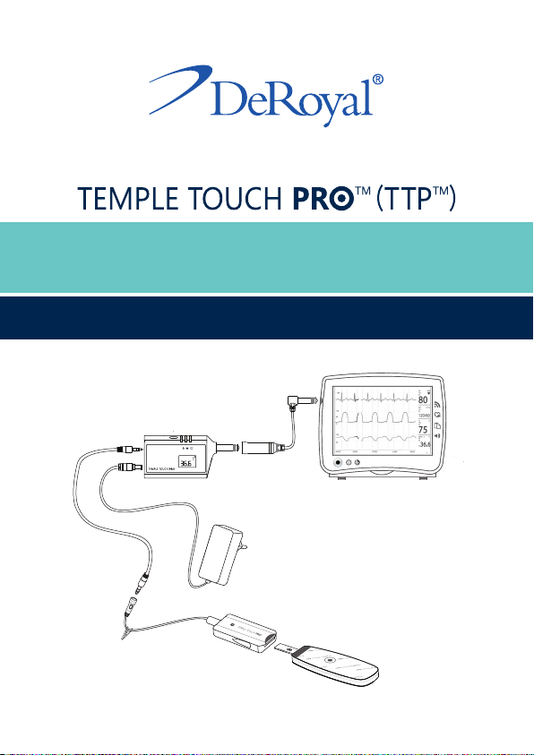
Non-Invasive Core Temperature Monitoring System
USER MANUAL
TM

1. Temple Touch Pro™ (TTP™) - Introduction
2. Intended Use
3. Warnings and Safety Notices
4. Temple Touch Pro™ - System Description
5. How Does Temple Touch Pro™ Work
6. Setting up Temple Touch Pro™
7. Instructions For Use
8. Troubleshooting - Errors
9. Care and Maintenance
10. Specications
11. Service and Warranty
Table of Contents
4
4
4
8
12
13
14
18
20
22
26
Abbreviaons Diconary
Abbreviaon FullTerm
TTP™ Temple Touch Pro™
MCU MonitorConnecngUnit
SCU SensorConnecngUnit
SU Sensor Unit
VSM VitalSignsMonitor

4
1 .Temple Touch Pro™ (TTP™) Introducon
The purpose of this document is to describe the proper way to
setup, use and maintain the Temple Touch Pro™ (TTP™) system.
The TTP™ system and the manual are intended to be used by
healthcare professionals in medical care environments only.
PriortoinstallingorusingtheTTP™system,readandfollowall
instrucons, labeling and accompanying documents supplied
withtheTTP™system.Failuretofollowinstruconscouldlead
tomisuseofthedevice,devicemalfunconorpaentinjury.
2. Intended Use of the TTP™
The TTP™ is intended to measure and monitor core body
temperatureof paents of allages,by applyinganSU on the
temple.
3. Warning and Safety Noces
WARNINGS:
1. The TTP™ system shall be aached to other equipment
only by authorized personnel.
2. Do not use the TTP™ system if one or more of its components
appeartobedamaged,broken,cracked,burned,torn,etc.
3. DonotaempttorepairormodifyanyoftheTTP™system
components.
4. Forsafeuse,useONLYoriginalTTP™systemcomponents
and accessories. Use only the original TTP™ MCU and
powersupplyspecied andsupplied for thisproductand
ceredforthecountryofuse.
5
5. The TTP™ MCU must be connected to the applied part
connector of a safety approved medical grade vital signs
monitor(VSM).TheconneconshallbemadetotheVSM
inputforappliedpartwhichismarkedasCFappliedpart.
6. Keeppowersupplyvisibleandaccessibleatallmes.The
power outlet shall be easily accessible. To disconnect the
TTP™ system from mains (power line): Disconnect the
power supply from the wall outlet.
7. Use only a properly grounded power outlet; do not use
extensioncablesormulpleportablesocketoutlets.
8. Donotallowthepowersupplytogetwet.
9. DonotusetheTTP™systeminthepresenceofaammable
anesthecmixtureornitrousoxide.
10. Do not use any of the TTP™ system components in an MRI
environment.
11. DonotallowthepaenttolieontheTTP™SCU.
12. Always posioncablesandwires away fromthepaent’s
body.
13. Do not use an exterior device to secure the TTP™ SU to the
paent.
14. Limit use of the TTP™ SU to 24 hours in order to reduce the
riskofskinirritaons.
15. In cases of intenonal hyperthermia or hypothermia
therapy use a dierent thermometer to measure body
temperature.

6
16. Wheneveryoudoubtthetemperaturereadingprovidedby
TTP™system,conrmtemperaturereadingwithaseparate
thermometer.
17. When disposing the TTP SU, follow facilies policies and
procedures for disposal of contaminated materials.
18. Performdecontaminaonprocedurespriortoreusingthe
TTP™system’sreusableparts(MCU,SCU,extensioncable,
monitor extension cable and power supply) and prior to
disposal.
19. Donotleavepediatricpaentsunaendedwhileusingthe
TTP™ system.
20. This device complies with part 15 of the FCC Rules.
Operaon is subject to the following two condions: (1)
This device may not cause harmful interference, and (2) this
device must accept any interference received, including
interferencethatmaycauseundesiredoperaon.
CAUTIONS:
1. DonotusetheTTP™SUondamaged/irritatedskin.
2. CleantheTTP™SCUbeforeconnecngtoanewTTP™SU.
3. Do not reaach the TTP™ SU as it might weaken the
adhesive,damagetheTTP™SU,orcompromisetheTTP™
system performance.
4. Followapplicableregulaonswhendisposingofthisdevice
and any of its electronic components.
7
NOTICES:
1. The TTP™ system meets medical electronic interference
requirements. If radio frequency interference occurs,
connect the TTP™ system to a power source.
2. Do not store any of the TTP™ system components in a wet
or damp place.
3. Do not spray, immerse or use abrasive cleaners or solvents
to clean the TTP™ system. Do not subject the TTP™ system
components to any process.
4. The TTP™ SU is not made with natural latex material.
5. The manufacturer declines any form of responsibility and
liability as an outcome of improper setup, or
storage or or repairs.
Follow
for use
Single use only
Class II equipment if
powered with Mean Well's
AC/DC adaptor GSMO6E12-
1PJ or equivalent
type CF
Keep dry

8
TM
Figure1
4. Temple Touch Pro™ - System Descripon
The TTP™ system connuously monitors the paent’s core
body temperature. The TTP™ system contains the following
components: a Sensor Unit (SU), which is connected to a Sensor
Connecng Unit (SCU) which is connected to the Monitor
Connecng Unit (MCU). The Monitor Connecng Unit (MCU)
isconnectedtoapowersupplyandtotheVitalSignsMonitor
(VSM).
A. MCU
B. SCU
C. SU
D. Extensioncable
E. Monitorextensioncable
F. Power supply
G. VSM
A
DF
E
G
B
C
9
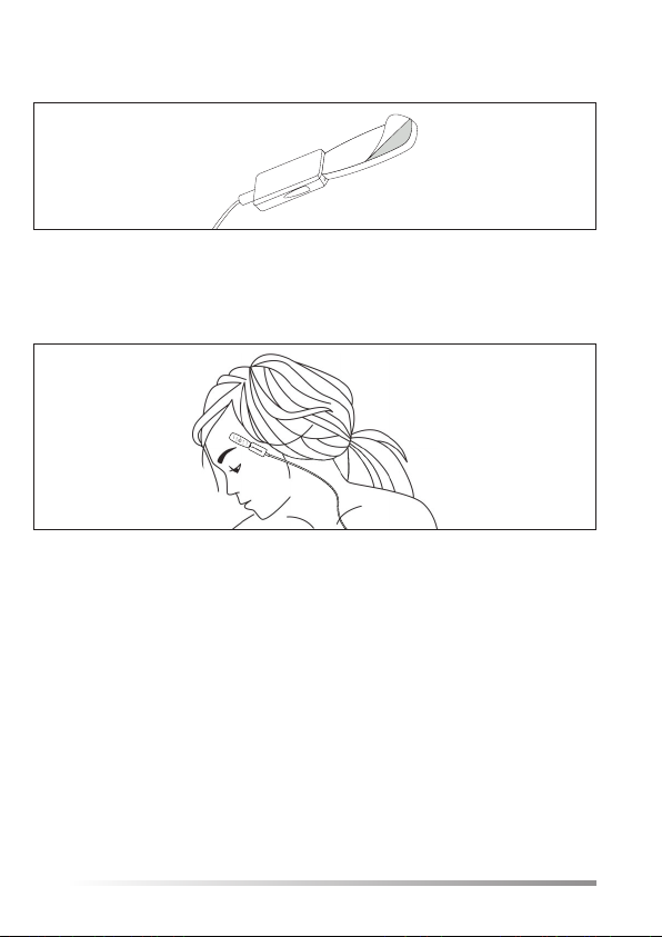
The TTP™ Sensor Unit (SU)
TheSUisanon-sterile,disposablesensingunitwhichisplaced
onthepaent’stemplefromtheinialstagesofmedicalcare
(suchassurgerypreparaon),andmaybeaxedtothepaent’s
temple unl it is no longer required to monitor the paent’s
coretemperature(suchas-upondischargefromPACU).
The SU is comprised of a temperature sensor module, a bio
compableadhesivelayer,withtwoisolaonlayersinbetween.
The TTP™ Sensor Connecng Unit (SCU)
The SCU is a cable with connector suitable to connect the SU
to the SCU.
The SU is connected to the SCU as shown below:
Figure2
Figure3
8
TM
Figure1
4. Temple Touch Pro™ - System Descripon
The TTP™ system connuously monitors the paent’s core
body temperature. The TTP™ system contains the following
components: a Sensor Unit (SU), which is connected to a Sensor
Connecng Unit (SCU) which is connected to the Monitor
Connecng Unit (MCU). The Monitor Connecng Unit (MCU)
isconnectedtoapowersupplyandtotheVitalSignsMonitor
(VSM).
A. MCU
B. SCU
C. SU
D. Extensioncable
E. Monitorextensioncable
F. Power supply
G. VSM
A
DF
E
G
B
C
9
The TTP™ Sensor Unit (SU)
TheSUisanon-sterile,disposablesensingunitwhichisplaced
onthepaent’stemplefromtheinialstagesofmedicalcare
(suchassurgerypreparaon),andmaybeaxedtothepaent’s
temple unl it is no longer required to monitor the paent’s
coretemperature(suchas-upondischargefromPACU).
The SU is comprised of a temperature sensor module, a bio
compableadhesivelayer,withtwoisolaonlayersinbetween.
The TTP™ Sensor Connecng Unit (SCU)
The SCU is a cable with connector suitable to connect the SU
to the SCU.
The SU is connected to the SCU as shown below:
Figure2
Figure3
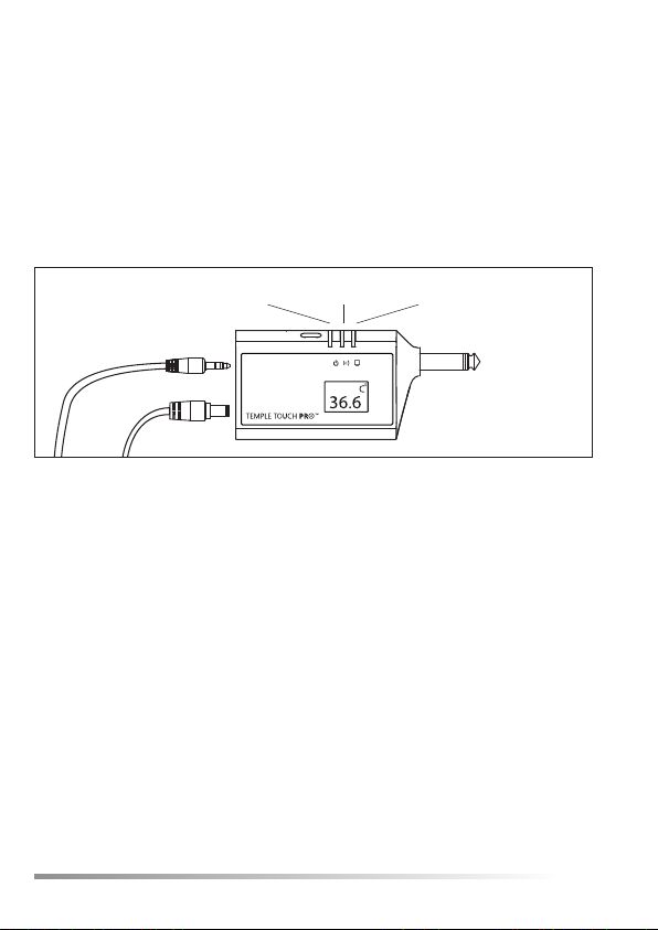
10
The TTP™ Monitor Connecng Unit (MCU)
The MCU receives data from the SU through the SCU and
transmits the informaon related to the paent’s core
temperature to the VSM. The MCU is connected to the power
supply via Inlet B.
The TTP™ system is designed to display operaon feedback
throughtheMCULEDsandtheSCULEDlocatedontheSCU.
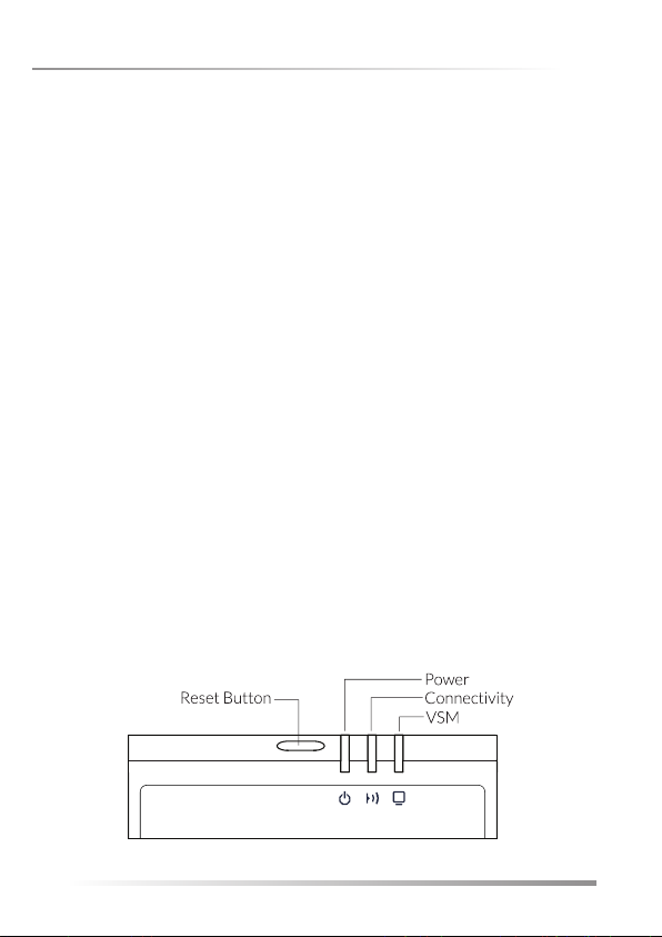
Figure4
Inlet A
Power Connecvity VSM
Inlet B
11
LED name Symbol Color Funconality Locaon
POWER Yellow Turns ON when the
MCU is properly
connected to a power
supply.
MCU
CONNECTIVITY Green BlinkswhentheMCU
is properly connected
to the SCU.
MCU
VSM Green Turns ON when the
MCU is properly
connected to the VSM
andfullyfunconing.
MCU
SCU Green Turns ON when
the SU is properly
connected to the
SCU.
SCU
TableA.1-LEDIndicaonDescripon:
10
The TTP™ Monitor Connecng Unit (MCU)
The MCU receives data from the SU through the SCU and
transmits the informaon related to the paent’s core
temperature to the VSM. The MCU is connected to the power
supply via Inlet B.
The TTP™ system is designed to display operaon feedback
throughtheMCULEDsandtheSCULEDlocatedontheSCU.
Figure4
Inlet A
Power Connecvity VSM
Inlet B
11
LED name Symbol Color Funconality Locaon
POWER Yellow Turns ON when the
MCU is properly
connected to a power
supply.
MCU
CONNECTIVITY Green BlinkswhentheMCU
is properly connected
to the SCU.
MCU
VSM Green Turns ON when the
MCU is properly
connected to the VSM
andfullyfunconing.
MCU
SCU Green Turns ON when
the SU is properly
connected to the
SCU.
SCU
TableA.1-LEDIndicaonDescripon:

12
Temporal
artery Dermis
Epidermis
Hypodermis
Heat transfer from TA to the Sensor Unit
Figure5
5. How does Temple Touch Pro™ work
Core temperature is dened as the temperature of the blood
owinthepulmonaryartery.Underknownparametersonecan
ulizeTemporalArterybloodowcharacteriscstoderivethe
core temperature.
The SU is aached to the skin above the Temporal Artery
and measures heat ux and the skin temperature above the
TemporalArtery.TheMCUacquiresthedatafromtheSUand
accuratelycalculatesthepaent’scoretemperature.
13
6. Seng up Temple Touch Pro™
Note!
Setup of the TTP system shall follow the sequence below:
1. Make sure the VSM is turned on and fully operative
according to the instructions provided by the VSM
manufacturer.
2. ConnectthepowersupplytotheMCU’spowersupplyinlet.
(DisplayMCUallsegmentswillappear for 2 seconds).
3. Connect the MCU to the VSM.
4. RestarttheMCUbypressingandholdingtheRESETbutton
for3secondsinthefollowingcases:
•AfterplacingtheSUonthepatientforthefirsttime(Referto
section7:“InstructionforUse”).
•IftheSUwasseparatedfromthepatient’sskinatanypoint
aftertheinitialplacement.
•AfteranycomponentoftheTTPSystem(MCU/SCU/SU)was
disconnectedfromarunningTTPsetup.
•If any abnormal outcome is displayed on the Vital Signs
Monitor.

14
Temple
3. Connect the SU to the SCU.
Upper side
Figure6
Figure7
7. Instrucons for Use
1. EnsuretheMCUisconnectedtotheVSMandtothePower
Supply(seesecon6above).
2. Ensure the paent’s temple is intact and use an alcohol
wipetocleananddisinfectthepaent’stemple.Allowthe
temple to completely dry (at least 2 minutes).
Note: The temple is located between the end of the hairline and
the eyebrow.
15
4. PeelthelinerotheSUtoexposetheadhesive(Thegure
showstheboompartoftheSU).
LimituseoftheSUto24hoursinordertoreducetheriskofskin
irritaons.
6. ConnecttheSCUtotheMCU.TheCONNECTIVITYLEDwill
startblinking,indicangtheMCUcommunicaonacvity.
At the same me, the SCU LED will turn on and stay on
constantly. The VSM will display temperature within less
than 3 minutes.
7. SupporttheSCUcablewiththeprovidedclip. Make sure
the SCU cable is placed loosely next to the paent to
ensuretheSUiskeptinplaceproperlyduringthemedical
procedures.
5. PlacethecenteroftheSUonthepaent’stemple.Gently
press the surrounding edge of the SU to ensure good
adhesiontotheskin.
Boom side
Figure8
Figure9

16
8. Innormalsystemacvity,theLEDsoperaonwilloccuras
describedintableA.1(LEDIndicaondescripon):Should
younoceadierentLEDfeedback,pleaserefertosecon
8:Troubleshoong.
How to transfer a paent connected to the TTP™ system?
Inordertotransferapaentfromonelocaontoanother:
1. DisconnecttheSCUfromtheextensioncable.Makesure
theSCUissecuredonthepaent’sgownandthatthe
SU remains in place, on the paent ’s temple properly
connected to the SCU.
2. Whenthepaentarrivesatthenextpointofcare,ensure
theMCUatthenewlocaonisalreadyconnectedtothe
VSM and to a power supply. Reconnect the SCU to the
new MCU. Then restart the MCU.
3. The VSM will display the paent’s temperature. Make
sure to follow steps 1-6 in this chapter (instrucon
for use) to ensure good temperature monitoring aer
paenttransfer.
17
How to remove the SU from the paent?
When corebody temperature monitoring is no longer
required,takethefollowingsteps:
1. Disconnect the SCU from the SU. Then remove the SU
fromthepaentbycarefullypullingthetabontheedge
of the SU. Use an alcohol swab if needed.
2. Dispose the SU safely. Follow applicable disposal
regulaons.
Shung down the MCU
Ingeneral,thereisnoneedtopowerotheTTP™Systemas
itcanstayconnectedtotheVSMatallmes.Toshutdown
the TTP™ system, disconnect the AC Power supply from Inlet
B of the MCU.
Switch temperature scale on MCU
MCU can display temperature measurements in either
Celsius or Fahrenheit. To switch scales (Celsius to
Fahrenheit and vice versa) press and release the RESET
button.

18
Whenanerroroccurs,thefollowingindicaonwarningswillappear:
8. Troubleshoong - Errors
TheTTP™systemisdesignedtodisplaysystemrelatedfeedback
warningsthroughitsLEDs array,pleaserefertotableA.1.For
LEDindicaonsatnormalfunconality.
Error Indicaon Possible Cause Instrucons
POWERLED
is OFF
The MCU is
not powered
properly.
1. Ensurethepowersupplyis
properly connected to a wall
outlet, and that the power
supply is properly connected to
the MCU.
2. IfPOWERLEDissllOFF,
replace power supply. Refer to
IFUsecon3.3-warningand
safetynoces.
3. IfPOWERLEDissllOFF,
replace MCU.
4. IfPOWERLEDissllOFF,
contact service.
ConnecvityLED
is OFF
VSMLED
is OFF
ERR4message
on LCD
Theconnecon
between the
SCU and the
MCU is lost.
1. EnsuretheSCUisproperly
connected to the MCU.
2. IfCONNECTIVITYLEDissllOFF,
replace SCU.
3. IfCONNECTIVITYLEDissllOFF,
replace MCU.
4. IfCONNECTIVITYLEDissllOFF,
contact service.
Power Connecvity VSM
SU Led
19
Error Indicaon Possible Cause Instrucons
SCULEDis
blinking
VSMLED
is OFF
ERR3message
on LCD
The SU is
not properly
connected
ordamaged
or the SCU is
damaged.
1. EnsuretheSUisproperly
connected to the SCU.
2. IfSCULEDissllblinking,
replace SU.
3. IfSCULEDissllblinking,
replace SCU.
4. IfSCULEDissllblinking,
contact service.
VSMLED
is constantly OFF
ERR5message
on LCD
TheMCU’s
ambient
temperature
reading
exceeds the
speciedrange
(15°C-40°C).
1. Ensurethattheambient
temperature is within the
speciedrange.
2. Assure that the MCU is not located
near extreme temperature heat
source.
3. Pressand hold theRESETbuon
for 3 seconds. Then wait 10
seconds.
4. IfVSMLEDissllo,replaceMCU.
5. If VSM LED is sll o, contact
service.
VSMLED
is constantly OFF
ERR1message
on LCD
There is a
problem with
theMCU’s
ambient sensor.
1. Replace MCU.
2. IfVSMLEDissllo,contact
service.
The VSM
reads 25°C or
45°C
ERR6message
on LCD
The measured
temperature
is outside of
thespecied
measuring
range.
POSSIBILITY OF
EXTREMEAND
DANGEROUS
PATIENT
TEMPERATURE
1. Ensure that the SU is properly
aachedtothetemple.
2. Checkambientcondionsaround
the paent, as well as paents
warmingorcoolingsystem.
3. Wait 3 minutes and check again
the LEDs on MCU and the VSM
reading.

20
9. Care and Maintenance
CAUTION:
• Do not expose the TTP™ system to extreme temperatures,
humidity,directsunlightorshock.
•KeeptheTTP™systemawayfromhotorboilingwaterand
chemicals.
•Do not spray cleaning solutions onto any of the TTP™
components. The system is NOT water resistant.
•Donot immerseorusewetfabriconany ofthesystem’s
componentsasmoisturemightdamagetheelectrical
components and lead to incorrect temperature
measurements.
Cleaning the MCU and SCU
CleantheMCUonanas-neededbasisorperfacilitypoliciesand
proceduresforcleaningelectronicequipment.
1. Disconnect MCU from power outlet and from the SCU.
Disconnect the MCU from the VSM.
2. Use a slightly damp so fabric moistened with a mild,
nonabrasivecleaningsoluontoclean thedevicesurface
andcables.Avoidspilloverofuidsintothesystem’sparts.
3. Drywithasofabric.
21
Disinfecng the SCU
1. Clean the SCU between each use.
2. Wipe down the SCU using a damp so fabric and 70%
isopropylalcohol.Avoidspilloverofuidsintothesystem’s
parts.
3. Drywithasofabric.
Storage
Noce: Do not store the TTP™ system components in a wet or
dampplaceasitmightdamagetheelectricalcomponents.
Store all TTP™ components at room temperature and in a dry
place when not in use.
Funconality Check
OnceEvery2years,usetheTTPFunconalityCheckkit.
Funconalitycheckinstruconswillbeprovidedinthekit.
Ifthecheckfailscontactservice.
Table of contents


