ST Group SPIDER ST 301 User manual

ST 301 "SPIDER"
WIRELINE ANALYZER
USER MANUAL
ST Group, Ltd.
St. Petersburg, Russia
+7 (812) 412-3321, +7 (812) 412-4051
info@smersh.pro
www. spymarket.com

Contents
1
CONTENTS
1
General Information……..……………………………………..…………………………………………………
4
1.1
Purpose and Capabilities………………………..………………………………………………………………………………………………
4
1.2
The KIT………………………………………………………………………………………………………………………………………...........
5
1.3
Description of Components……………………………………………………………………………………………………………………
8
1.4
Power supply………………………………………………………………………………………………………………………………………….
11
1.5
Specifications………………………………………………………………………………………………………………………………………….
12
2
Connecting to the Cables……………………………….………………………………………………………………………………….
13
2.1
Connecting to the Power Mains…………………………………………………………………………………………………………….
13
2.2
Connecting to the LAN Cable….………………………………………………………………………………………………………….…
13
2.3
Connecting to the Telephone Cable….……………………………………………………………………………………………………
14
2.4
Connecting to the Low-Current Multi-Wire Cable, which is Not Equipped with Connector…….……….…
15
2.5
Connecting to the Shield of Low-Current Cable…………………….…………..……………………………………...........
15
2.6
Connecting to the TV SET and to the Television Cable…………………….….……………………………………………..
17
3
Interface Settings…………….…………………………………………………………………………………………………………………
21
3.1
Turning on/off……..…………………………………………………………………………………………………………………………………
21
3.2
The Analyzer Main Menu………………………………………………………………..…………………………………………………….
21
3.3
Information Line…………………………………………………………………………………………………………………………..………..
21
3.4
SETTINGS (Service Mode)…….……………………………………………………………………………………………………………….
22
3.4.1
Date Setting……………………………………………………………………………………………………………………………………………
22
3.4.2
Time Setting……………………………………………………………………………………………………………………………………………
23
3.4.3
Interface Language Setting……………………………………………………………………………………………………………………
23
4
Electronic Switch Settings……………………………………………………………………………………….
24
4.1
Standard Settings………………………………………………………………………………………………………………………….……….
26
5
DEVICES ………………………………………….…………………………………………………….……………..
29
5.1
LOW-FREQUENCY AMPLIFIER (LFA)………………………………………………………………………….
29
5.1.1
LFA Main Menu……………………………………………………………………………….………………………………………………………
29
5.1.2
Gain Setting…………………………………………………………………………………………………………………………………….……..
31
5.1.3
Bias Voltage Setting……………………………………………………………………………………………………………………………….
31
5.1.4
AUTOMATED Mode………………………………………………………………………………………………………………………………….
31
5.1.5
OSCILLOSCOPE……………….……………………………………………………………………………………………………………………..
31
5.1.6
SPECTRUM ANALYZER……………………………………………………………………………………………………………………………
32
5.2
WIRED RECEIVER (WR) ………………………………………………………………………………………….
34
5.2.1
Cable Type Selection……………..……………………………………………………………………………………………………………….
34
5.2.2
Frequency Range Selection …………………………………………………………………………………………………………………..
35
5.2.3
Power Mains Testing (PANORAMA Mode)…………………………………………………………………………………………….
35
5.2.4
DIFFERENTIAL Mode……………………………………………………………………………………………………….……………………..
37
5.2.5
Signal Analysis at a Fixed Frequency…………………………………………………………………………………………………….
38
5.2.6
OSCILLOSCOPE…………………..………………………………………………………………………………………………………..………
39
5.2.7
AUTOMATED mode……………………………………………………………………………………………………………………………..….
40
5.2.8
Signal Analysis at a Fixed Frequency (in AUTOMATED mode) ……………………………………………….…………..
42
5.2.9
Low-Current Cable Testing ……………………………………………………………………………………………………………………
43
5.2.10
Low-Current Cable Testing Features.……………………………………………………………………………………………………
44

Contents
2
5.3
NON-LINEAR JUNCTION DETECTOR (NLJD)……………………………………………………………….
45
5.3.1
General Information……………………………………………………………………………………………………………………………….
45
5.3.2
NJLD Main Menu……………….……………………………………………………………………………………………………………………
46
5.3.3
Probing Signal Level Setting……….…………………………………………………………………………………………………………
47
5.4
REFLECTOMETER (REF)………………………………………………………………….………………………..
48
5.4.1
REF Main Menu…………….…………………………………………………………………………………………………………………………
48
5.4.2
Shortening Factor Setting ………………….………………………………………………………………………………………………..
50
5.4.3
AUTOMATED Mode……………………………………………………………………………..………………………………………………….
50
5.4.4
MANUAL Mode…………………………………………………………………………………………………………………………………………
51
RECOMMENDATIONS FOR USE…………………………………………………………………………………………………………
53
6
Types of the Wire Eavesdropping Devices…………………………………………………………………………………….
53
6.1
Wire Dynamic and Electret Microphones……………………………………………………………………………………………….
53
6.2
High-Frequency Wire Transmitters…….…………………………………………………………………………………………………
53
6.3
Telephone Transmitters………………………………………………………………………………………………………………………….
53
6.4
Audio Recorder Adapters……………………………………………………………………………………………………………………….
54
7
Basic Operations…………………………………………………………………………………………………………………………………
55
7.1
Basic operation #1. Detection of LF Signals in Low-Current Cables………………………………………………..
55
7.1.1
Implementation of Basic Operation #1. Analog Telephone Line Testing ……………………………………………
55
7.2
Basic operation #2. Detection of HF Signals in Power Mains and Low-Current Cables.………………….
57
7.2.1
Implementation of Basic Operation #2. Power Mains (220 V/50 Hz) Testing ……………………………….….
58
7.2.2
Implementation of Basic Operation #2. Analog Telephone Line Testing ……………………………………………
60
7.2.3
Features of Testing of the HF Television Cables……………………………………………………………………………………
61
7.3
Basic operation #3.Detection of Nonlinearity in the Cable …………….………………………………………………
62
7.3.1
Implementation of Basic Operation #3. Analog Telephone Line Testing……………………………….……………
62
7.4
Basic operation #4. Detection of Heterogeneity in the Cable……………………..…………………………………..
65
7.4.1
Theoretical Aspects of the Reflectometry……….………………………………………………………………………………….
66
7.4.2
Testing of the Multi-Wire Cable ………………………………………….……………………………………………………………….
73
7.4.3
Testing of the Two-Wire Cable (a Pair of the Multi-Wire Cable) ……………………………………………………….
73
7.4.4
Procedure for Testing of the Two-Wire Cable ………………………………………….…………………………………………
74
7.4.5
Procedure for Testing of the Multi-Wire Cable…………………………………………………………………………………….
75
7.5
Basic operation #5. Localization of the Detected Eavesdropping Devices………………………………………
76
7.5.1
Acoustic Method of Localization…………………………………………………………………………………………………………….
76
7.5.2
Localization by Means of ST 301 and NLJD…………………………………………………………………………………………..
76
8
Software……………………….……………………………………………………………………………………………………………………...
78
8.1
General Information.............................................................................................................
78
8.2
LFA…………………………………………………………………………………………………………………………………………………………
80
8.3
WR…………………………………………………………………………………………………………………………………………………………
88
8.4
NLJD…………………………………………………………………………………………………………………………………………………………
96
8.5
REF…………………………………………………………………………………………………………………………………………………………
101
REFERENCE INFORMATION………………………………………………………………………………………………………………
111
9
Controls……………………………………….………………………………………………………………………..
111
9.1
Initial Settings…………………………………………………………………………………………………………………………………………
111

Contents
3
9.2
LFA…………………………………………………………………………………………………………………………………….……..............
112
9.3
WR….………………………………………………………………………………………………………………………………….…….............
113
9.4
NLJD ……………………………………………………………………………………………………………………………………………………….
116
9.5
REF……………………………………………………………………………………………………………………………………….………………….
116
10
Information on Cables……………………………………………………………………………………………………………………….
117
10.1
"Twisted Pair"Type Cable……………………………………………………………………………………………………………….…….
117
10.2
RJ Connectors ……………………………………………………………………………………………………………………….………………
117
10.3
Wiring of a Cable Consisting of Four Twisted Pairs of Wires……………………………………………….……………….
117
10.4
Crossover Cable Wiring Scheme …………………………………………………………………………………………………………..
118
10.5
Wiring of a Cable Consisting of Three, Two and One Pair of Wires….………………………………………………….
119
10.6
Telephone Cable……………………………..……………………………………………………………………………………………………..
119

GENERAL INFORMATION
4
1. GENERAL INFORMATION
The user manual describes the principle of operation of the ST 301 "SPIDER" wireline analyzer
(hereinafter "Analyzer" or "ST 301"). The document contains hyperlinks that allow you to go to
the text fragments of interest.
1.1. PURPOSE AND CAPABILITIES
The Analyzer is designed to detect and localize eavesdropping devices that are galvanically
connected to power mains and low-current cables.
In the ST 301, passive and active modes of operation are used to detect enabled, switched off,
or faulty eavesdropping devices.
Functionally the Analyzer consists of four components (DEVICES):
1. LOW FREQUENCY AMPLIFIER (LFA)
2. WIRE RECEIVER (WR)
3. NON-LINEAR JUNCTION DETECTOR (NLJD)
4. REFLECTOMETER (REF)
FUNCTIONALITY:
detection and the analysis of signals cable (dynamic and electret) microphones in low-
current cables;
activation of electret cable microphones by giving to the cable of bias voltage for their
detection;
detection of signals of the eavesdropping devices transferring information on power mains
and low-current cables in frequency range of 100 kHz - 180 MHz;
detection of unauthorized galvanic connections to the cables using a NLJD and the REF;
measurement of AC and DC voltage in the low-current cables.

GENERAL INFORMATION
5
1.2. THE KIT
1.
Main unit..………………………………………………………………………………………………….
1
2.
Charger of the main unit………………………………………………………………………….
1
3.
Flash card …………………………………………………………………………………………………
1
4.
Mini-USB patch cord………………………………………………………………………………...
1
5.
Television splitter……………………………………………………………………………………..
1
6.
Headphones……………………………………………………………………………………………….
1
7.
Adapter for testing of the power mains…...…………………………………………….
1
8.
TV(m)/F(m) adapter………………………………………………………………………………...
3
9.
TV(f)/F(m) adapter……………………………………………………………………………………
1
10.
TV(f)/TV(f) adapter…………….…………………………………………………………………….
1
11.
RJ11 (1/2) splitter ……………………………………………………………………………….….
1
12.
RJ45 (1/2) splitter …...……………………………………………………………………………..
1
13.
RJ11 socket ………………………………………………………………………………………………
1
14.
RJ45 socket……………………………………………………………………………………………….
1
15.
RJ45 short-circuit socket…….……………………………………………………………………
1
16.
Adapter and screwdriver for connecting to the multi-wire cable………..…
1
17.
Case……………………….……………………………………….…………………………………………
1
18.
Television cable TV(f)/TV(m) …………………………………………………………………..
1
19.
Patch cord RJ45/TV(m) for connecting to the TV socket TV(f)…..………….
1
20.
Patch cord for connecting to the RJ45 PC socket…………………………………….
1
21.
Patch cord for connecting to the RJ11 telephone socket………….…………….
1
22.
Patch cord with a needle for connection to the cable shield……………………
1

GENERAL INFORMATION
6
Fig.1
For transportation and storage of the ST 301 the shockproof, waterproof plastic case is used.

GENERAL INFORMATION
7
Numbers indicate the elements of the kit, laid in a certain place of the lodgment.
The designations correspond to the numbering presented in item 1.2.1.
1.3. DESCRIPTION OF COMPONENTS
1.3.1. THE MAIN UNIT WITH THE ELECTRONIC SWITCH
Purpose of the main unit:
forming and generating probing signals to the cables;
switching control of the tested multi-wire cables;
analysis of incoming signals and responses of probing signals;
Analyzer modes control.
The appearance of the main unit is shown in Fig.2

GENERAL INFORMATION
8
Fig.2
Designation
in Fig.2
Designation
on main unit
Use
1
Power tumbler / volume control
2
PHONES
Slot for connection of headphones
3
SHIELD
Slot for connection of the shield of the tested cable
4
INPUT
Input connector of the Electronic Switch
5
Analyzer monitor
6
Keyboard
F1-F4
"Hot" buttons which purpose depends on the set operation mode

GENERAL INFORMATION
9
Designation
in Fig.2
Designation
on main unit
Use
ESC
Action canceling button (return on "one step")
FUNC
Button for turn on of various modes
ENTER
Button for confirm action
MODE
Button to call the mode selection menu
7
Accumulator charge indicator
8
Slot for connection of the charger
9
Mini-USB connector for connection to the PC
10
Information plate with the serial number
11
Support
12
Integrated speaker phone
ELECTRONIC SWITCH
The Analyzer has an integrated Electronic Switch (hereinafter "Switch") designed to increase
the efficiency of testing multi-wire cables.
Automated and manual control modes of the Switch allow to connect all combinations of wire
pairs of a multi-wire cable to the RJ45 socket "INPUT" (Fig.2, item 4).
The control of the Switch is impossible when testing power mains.
1.3.2. ADAPTER FOR TESTING OF THE POWER MAINS
The adapter (Fig.1, item 7) is used for connect the main unit to the tested power mains. LED
indicator in the plug, indicates the presence of voltage in the tested cable.
The adapter has the RJ45 plug. The contacts #1 and #2 are connected. Other contacts are not
involved.
1.3.3. PATCH CORD FOR CONNECTING TO THE PC SOCKET (RJ45)
Standard patch cord (Fig.1, item 20), is used for connect the main unit to RJ45 PC socket.
1.3.4. PATCH CORD FOR CONNECTING TO THE TELEPHONE SOCKET (RJ11)
The patch cord (Fig.1, item 21) is used when testing the telephone cable that are equipped
with RJ11 sockets.
The patch cord is equipped with RJ45 and RJ11 connectors. On the RJ45 connector six contacts
are involved (#2 - #7). Two extreme contacts (#1 and #8) are not connected.
1.3.5. PATCH CORD RJ45/TV(M) FOR CONNECTING TO THE TV SOCKET TV(F)
The patch cord (Fig.1, item 19) is used when testing television receivers, cable and terrestrial
television cables.
The cable is equipped with RJ45 and TV(f) connectors. On the RJ45 connector, only two
extreme contacts (#1 and #2) are involved. Other contacts are not connected.

GENERAL INFORMATION
10
1.3.6. PATCH CORD WITH A NEEDLE FOR CONNECTING TO THE CABLE SHIELD
The patch cord with a needle (Fig.1, item 22) is used when testing multi-wire shielded cables,
the screen of which is not connected to the connector. It connects to the "SHIELD" connector of
the main unit. On the wire there is a pin plug and a needle probe. The needle pierces the outer
insulation of the cable under test and provides contact with the screen.
1.3.7. ADAPTER FOR CONNECTING TO THE MULTI-WIRE CABLE
The adapter (Fig.1, item 16) is used to connect low-current cables with no connectors. When
connecting such cables (twisted pair type), it is recommended to take into account the color
scheme of wires of a cable (item 10.3).
1.3.8. PLAYER OF THE TEST SOUND (PTS). The player is not included in the package.
A player is required to search for eavesdropping devices. Any portable device equipped with a
speaker (smartphone, tablet, voice recorder) can be used.
Purpose of the PTS:
creation of an acoustic signal (the correlation of this signal and the information obtained
using the ST 301 means that there is an active eavesdropping device with an unencrypted
transmission channel in the room);
forced inclusion of eavesdropping devices equipped with a VOX activation system;
localization of detected listening devices;
creation of the "masking noise" during the search operations.
Files with sounds are recorded on a USB drive (fig.1, 7). The user can use their own sound files
that are optimally suited to the situation in which the search event is held (noise in the office,
people talking, music, etc.).
1.3.9. RJ45 SHORT-CIRCUIT SOCKET
This socket (Fig.1, item 15) is used for short circuit of all wires of the cable equipped with the
RJ45 connector at its test by NLJD.
1.3.10. MINI-USB PATCH CORD
Mini-USB patch cord (Fig.1, item 4) is used to connect the main unit to the USB port of a PC.
1.3.11. SPLITTERS AND ADAPTERS
The Analyzer kit contains a set of splitters and adapters used to test various types of cables.
Options for their use are described in item #2 ("Connecting to the cables").

GENERAL INFORMATION
11
1.4. POWER SUPPLY
The operation of the Analyzer is allowed only from the built-in accumulator.
A fully charged accumulator provides the Analyzer operation for 3 hours.
The accumulator charge level is shown in the Information line (Fig.22, item 3) on the screen.
The accumulator is charged using the charger (Fig.1, item 2).
To do this, insert the charger plug into the connector (Fig.2, item 8) on a side panel of the
Analyzer and connect the charger to the 220 V / 50 Hz power mains.
Charging is followed by a red luminescence of the indicator of connection of the charger (Fig.2,
item 7) on a side bar of the Analyzer.
Full charge time is not more than 5 hours. When charging is complete, the indicator changes
from red to green.
It is forbidden t o charg e t h e accumulator during operat i on of the Analyzer!

GENERAL INFORMATION
12
1.5. SPECIFICATIONS
LOW FREQUENCY AMPLIFIER (LFA)
Frequency range, Hz
20 - 25000
Input resistance, kOhm
200
Adjustment range of gain, dB
0 - 60
The maximum signal amplitude on an input, V
10
Spectral density of noise voltage, nV/Hz
6
Bias voltage values, V
0, ±5, ±10,
±15, ±20, ±26
Form of representation of a signal
Oscillogram
Spectrogram
Measurement range on a direct current, V
±80
WIRE RECEIVER (WR)
Frequency range, MHz
0.1 - 180
Time of scanning of all range, sec
0.3 - 1
Minimum level of detected signal in AUTOMATED mode, dBm
-60
Dynamic range, dB
50
Input resistance, Ohm
50
Demodulation
AM, FM
Bandwidth of the filter, kHz
180
The maximum allowed voltage in the cable, V
250 (AC),80 (DC)
Data representation form
Spectrogram
Oscillogram
Table
NON-LINEAR JUNCTION DETECTOR (NLJD)
Level (amplitude) of the probing signal, V
±14
Frequency of the probing signal, Hz
60
Separate indication of even and odd harmonics
yes
Minimum detectable level of non-linear distortion, %
0.1
REFLECTOMETER (REF)
Range of distances, m
3 - 150
Error of measurements, m
±0,6
The ability to work on cables under voltage
no
Power supply
The built-in lithium-polymer accumulator, V
3.7
Power consumption, W
<1
Operating time at the maximum power consumption, hour
>3
Charging interval of completely discharged accumulator, hour
5
Weight and dimensions
Dimensions of the main unit (length, width, height), mm
165 x 98 x 40
Mass of the main unit, kg
0.47
Packaging dimensions (length, width, height), mm
390 x 310 x 170
Mass of the kit in packaging, kg
4.4

CONNECTING TO WIRE LINES
13
2. CONNECTING TO THE CABLES
2.1. CONNECTING TO THE POWER MAINS
The Analyzer connected to the power mains using an adapter (Fig.1, item 7).
The scheme of connection is shown in Fig.3.
Fig.3
The adapter (in the plug) is connected to the socket of the tested cable, other end of the cable
is connected to the slot of "INPUT" of the main unit.
The LED indicator on the adapter shows existence or lack of voltage in the tested cable.
2.2. CONNECTING TO THE LAN CABLE
The LAN cables can be equipped with RJ45 plugs or RJ45 sockets.
2.2.1. CONNECTING TO THE LAN CABLE EQUIPPED WITH RJ45 PLUGS
When testing LAN cable, without the need for parallel connection of terminal devices, the LAN
cable equipped with a plug of RJ45 is connected directly to the slot of "INPUT" of the main unit.
The scheme of connection is shown in Fig.4, 2A option.
If test assumes parallel connection of terminal devices (PC, network printer, etc.), are used:
patch cord (Fig.1, item 20);
RJ45 splitter (Fig.1, item 12);
RJ45 socket (Fig.1, item 14).
The scheme of connection is shown in Fig.4, 2B option.
Fig.4

CONNECTING TO WIRE LINES
14
2.2.2. CONNECTING TO LAN CABLES EQUIPPED WITH RJ45 SOCKETS
When testing LAN cables, without the need for parallel connection of terminal devices,
connection of the main unit to the PC socket is made by means of a patch cord (Fig.1, item 20).
The scheme of connection is shown in Fig.5, 2C option.
If test assumes parallel connection of terminal devices, for connection it is necessary to use:
patch cord (Fig.1, item 20)
RJ45 splitter (Fig.1, item 12)
The scheme of connection is shown in Fig.5, 2D option.
Fig.5
2.3. CONNECTING TO THE TELEPHONE CABLE
Telephone cables can be equipped with RJ11 plugs or RJ11 sockets.
2.3.1. CONNECTING TO THE TELEPHONE CABLE EQUIPPED WITH RJ11 PLUG
In the case when there is no need for parallel connection of terminal devices (telephone set or
fax), the main unit is connected to the telephone cable with a patch cord equipped with RJ11 plug
(Fig.1, item 21) through the RJ11 socket (Fig.1, item 13).
The scheme of connection is shown in Fig.6, 3A option.
If test assumes parallel connection of terminal units (telephone or fax), are used:
patch cord (Fig.1, item 21);
RJ11 splitter (Fig.1, item 11);
RJ11 socket (Fig.1, item 13).
The scheme of connection is shown in Fig.6, 3B option.
Fig.6

CONNECTING TO WIRE LINES
15
2.3.2. CONNECTING TO THE TELEPHONE CABLE EQUIPPED WITH THE RJ11 SOCKET
When testing a telephone cable (without the need for parallel connection of terminal
equipment), the main unit is connected to the RJ11 socket using a patch cord (Fig.1, item 21).
The scheme of connection is shown in Fig.7, 3C option.
Options 3D and 3E show methods of parallel connection to telephone cables when using
terminal devices (telephone or fax).
Option 3D is applied when the telephone cable is equipped with the RJ11 socket. In this
case, for connection of the main unit it is necessary to use the RJ11 splitter (Fig.1, item 11) and a
patch cord (Fig.1, item 21).
Option 3E is applied when the telephone cable is equipped with the RJ11 double socket. In
this case, the main unit is connected to one of two slots of the socket by means of a patch cord
(Fig.1, item 21), and the telephone or fax by means of a regular cable is connected to other slot.
Fig.7
2.4. CONNECTING TO THE LOW-CURRENT MULTI-WIRE CABLE, WHICH
IS NOT EQUIPPED WITH CONNECTOR
For test of the low-current multi-wire cables which are not equipped with a plugs or sockets,
use the adapter (Fig.1, item 16). The scheme of connection is shown in Fig.8.
Fig.8
When connecting a LAN cable to the adapter, use the scheme (item 10.3).
This connection option is used when testing low-current cables using any device.
2.5. CONNECTING TO THE SHIELD OF LOW-CURRENT CABLE
When testing LAN cables, it is necessary (including) to test pairs consisting of wire of the
multi-wire cable and the cable shield. If the cable shield is connected to the grounding contact of
a socket or plug, use a "grounded" patch cord (Fig.1, item 20). Sometimes the shield of the cable
does not connect to the grounding pin of a socket or plug.

CONNECTING TO WIRE LINES
16
In addition, the shielded cable under test may not be equipped with an socket or plug. In this
case, connecting the main unit with a shielded patch cord will not provide the cable shield contact
with the grounding contact ST 301.
For connection of the shield it is necessary to use a patch cord with a probe needle (Fig.1, item
22) equipped with a probe needle. This needle punctures the isolation of the tested cable and
provided contact with the shield.
The other end of this patch cord is equipped with a jack that connects to the "SHIELD" slot of
the main unit.
The scheme of connection to shielded cable (which no equipped with socket and plug) using
the adapter (Fig.1, item 16) and a patch cord with a probe needle is shown in Fig.9.
Fig.9
The scheme of connection of the shielded cable equipped with a plug is shown in Fig.10.
Fig.10
The cable is connected directly to the "INPUT" slot of the main unit. The contact with the cable
shield is provided by means of the patch cord with the probe needle (Fig.1, item 22).
The scheme of connection of the shielded cable equipped with the socket is shown in Fig.11.
Fig.11
The main unit is connected to the socket by means of the patch cord (Fig.1, item 20).
The contact with the shield is provided by means of the patch cord with the probe needle
(Fig.1, item 22).
CONNECTING TO WIRE LINES
17
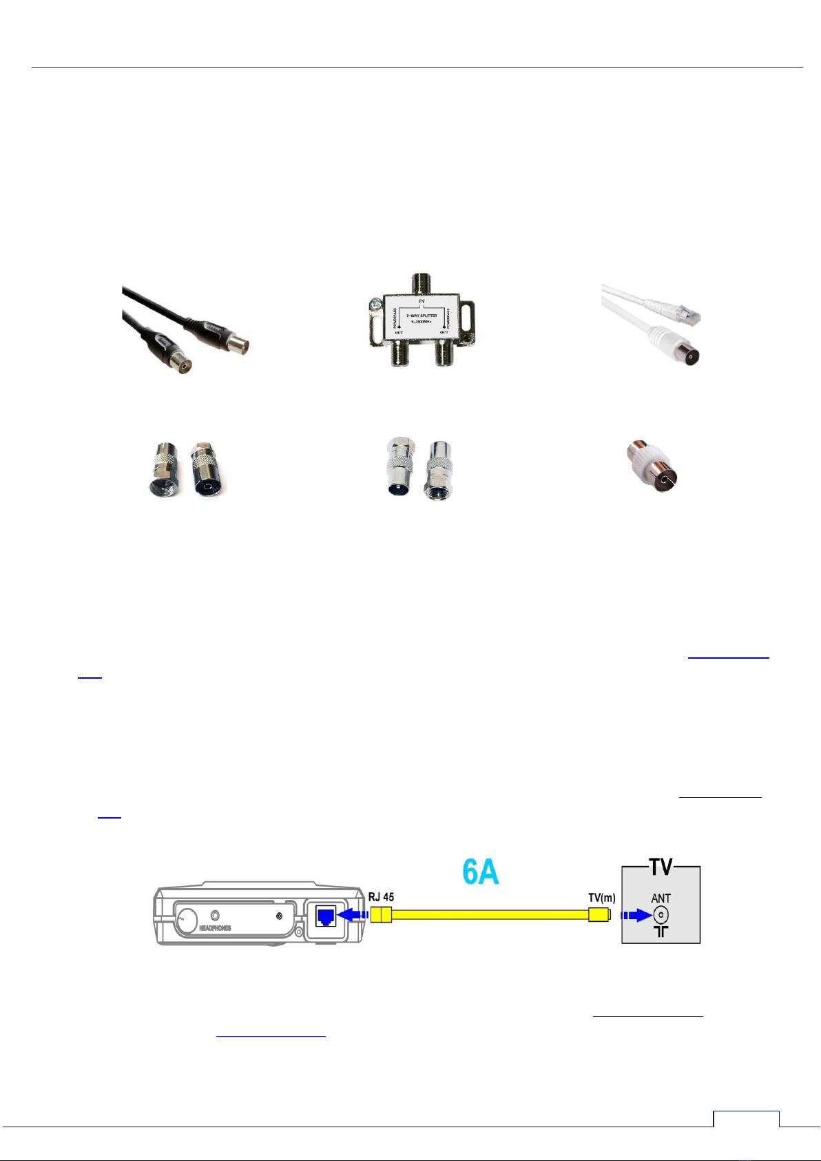
2.6. CONNECTING TO THE TV SET AND TO THE TELEVISION CABLE
Television systems use coaxial cables equipped with plug-in connections of two main types (F-
type and TV-type). Each of them can be a pin (designated by "male" or "m") or a socket
(designated by "female" or "f").
For connection of the main unit to the TV, the splitter or to a television cable different cables
and adapters from the ST 301 kit are used.
The appearance and names of the components are shown in Fig. 12.
Cable TV(m)/TV(f)
TV splitter
Cable RJ45/TV(m)
Adapter F(m)/(TVf)
Adapter F(m)/TV(m)
Connector TV(f)/TV(f)
Fig.12
When testing television cables WR is used. Regardless of what option of connection is used,
switching to an input of the main unit is made by means of the RJ45/TV(m) patch cord (Fig.1, item
19).
In the Switch it is necessary to set pair of wires #1 and #2 as this pair is involved in the
connector of a cable.
2.6.1. CONNECTING TO THE TV SET AND TO THE TV SOCKETS
The main unit is connected to an antenna input of the TV set using a patch cord (Fig.1, item
19). The scheme of connection is shown in Fig.13.
Fig.13
The main unit is connected to the television socket using a patch cord (Fig.1, item 19)and the
TV(f)/TV(f) adapter (Fig.1, item 10). The scheme of connection is shown in Fig.14.

CONNECTING TO WIRE LINES
18
Fig.14
When ST 301 is connected in parallel to the TV cable, are used:
RJ45/TV(m) patch cord (Fig.1, item 19)
TV splitter (Fig.1, item 5)
TV(m)/TV(f) television cable (Fig.1, item 18)
F(m)/TV(m) adapter (Fig.1, item 8)
F(m)/TV(f) adapter (Fig.1, item 9)
TV(f)/TV(f) adapter (Fig.1, item 10)
The scheme of connection is shown in Fig.15.
Fig.15
2.6.2. CONNECTION TO THE ANTENNA CABLE
The main unit is connected to the antenna cable using the patch cord (Fig.1, item 19)and the
adapter (Fig.1, item 10).
The scheme of connection is shown in Fig.16.
Fig.16
When ST 301 is connected in parallel to the TV cable and the TV set, are used:
RJ45/TV(m) patch cord (Fig.1, item 19)
TV splitter (Fig.1, item 5)
TV(f/f) adapter (Fig.1, item 10)
TV(m)/TV(f) television cable (Fig.1, item 18)
F(m)/TV(m) adapter (Fig.1, item 8)
F(m)/TV(f) adapter (Fig.1, item 9)

CONNECTING TO WIRE LINES
19
The scheme of connection is shown in Fig.17.
Fig.17
If the TV set or other terminal unit has the antenna input equipped with the F-type connector,
then for parallel connection are used:
RJ45/TV(m) patch cord (Fig.1, item 19)
TV splitter (Fig.1, item 5)
TV(m)/TV(f) television cable (Fig.1, item 18)
F(m)/TV(m) adapter (Fig.1, item 8)
F(m)/TV(f) adapter (Fig.1, item 9)
TV(f/f) connector (Fig.1, item 10)
The scheme of connection is shown in Fig.18.
Fig.18.
2.6.3. CONNECTION TO THE EXTERNAL TV-SPLITTER
For connection to the external TV-splitter are used:
RJ45/TV(m) patch cord (Fig.1, item 19)
TV splitter (Fig.1, item 5)
TV(m)/TV(f) television cable (Fig.1, item 18)
F(m)/TV(m) adapter (Fig.1, item 8)
F(m)/TV(f) adapter (Fig.1, item 9)
TV(f/f) adapter (Fig.1, item 10)
Table of contents
Other ST Group Measuring Instrument manuals

Popular Measuring Instrument manuals by other brands

Bosch
Bosch LR 7 Professional Original instructions

Precision Digital Corporation
Precision Digital Corporation PROVU PD6300 Series instruction manual

Tintometer
Tintometer Lovibond MD 200 instruction manual

Beck
Beck 990 Series manual

GreenValley
GreenValley LiBackpack C50 user guide

Emtec
Emtec BioProTT operating instructions


