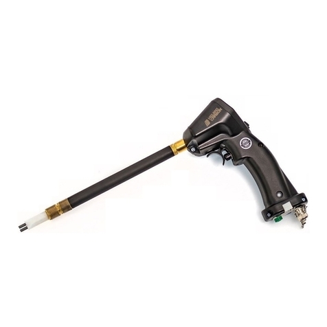
HELWIG CARBON BPK-Probe User manual

Page 1of 7
BPK –Probe™
Shaft Voltage Detection Device

Page 2of 7
Operating Guide
BPK-Probe™ Important Safety Information
You must understand all the safety statements in this manual prior to operating the BPK-Probe™
The WARNING designation indicates a potentially hazardous situation that, if not
avoided, could result in death or serious injury.
The BPK-Probe™ is designed to be in direct contact with rotating motor shafts. Rotating
motion can be dangerous; even smooth, slowly rotating shafts can grip clothing, and
mere skin contact can force an arm or hand into a dangerous position. Injuries due to
contact with rotating parts can be severe.
All power sources for machines are potential sources of danger. When using electrically
powered or controlled machines, the equipment as well as the electrical system itself
must be properly grounded. High pressure systems, too, need careful inspection and
maintenance to prevent possible failure from pulsation, vibration, or leaks. Such a
failure could cause, among other things, explosions or flying objects.
While never a substitute for appropriate machine guards, personal protective equipment
must always be worn around rotating motor shafts. It is important to note that
protective clothing and equipment can create hazards. For example, a protective glove
can become caught between rotating parts, or a respirator facepiece can hinder the
wearer’s vision.
Follow all safety precautions when working with rotating equipment.
The BPK-Probe™ should be used by qualified, trained personnel ONLY.

Page 3of 7
Purpose of the BPK-Probe™
The BPK-Probe™ is a complete kit including everything you need to determine risk to your motor
from damaging bearing discharges. It also demonstrates the effectiveness of a Bearing Protection
Kit (BPK) and allows for test data to be stored in on-board memory and/or on an oscilloscope.
Each kit includes everything you need to test and document the risk to your motor from
damaging Bearing Discharges.
BPK-Probe™ Features
Enhansed color LCD screen with with Probe status icons and real time visual test results.
On-Board memory stores test data plus the Probe includes a BNC output for closer analysis of
captured test data on an included Tablet Oscilloscope.
Thin Sensor Tip design for ease of accessability with field replaceable Sensor Tips
Two quick exchange Extension Tubes for hard to access motor shafts.
USB Memory Stick and Micro SD Card and Reader for downloading test results from the Probe or
oscilloscope –including captured video.
Memory stick includes Operator manuals for both the BPK-Probe and the Tablet oscilloscope.
All cables needed to download data and charge the batteries on the BPK-ProbeTM and oscilloscope
A durable hardshell case with custom foam to protect your investment.

Page 4of 7
BPK-Probe™Instructions for Use
Step 1: Prepare the BPK-Probe™
Follow all safety precautions when working with rotating equipment.
The BPK-Probe™ kit comes with everything you need to complete and document a bearing
discharge test in the field or back at the shop. The LCD screen includes Probe and test-status
ICONS and displays/stores test results for immediate on-site feedback. A unique feature allows the
user to test the motor as-is, without protection then again test the motor but this time with Helwig’s
embedded Bearing Protection Kit™(BPK) enabled. With the embedded BPK enabled the user can
measure the effectiveness of the grounding solution. In addition, the BPK-ProbeTM has an on-board
micro SD card for recording/downloading test results. For a more detailed analysis of the data
captured by the BPK-Probe™ it includes a BNC output and cable that are easily connected to the
included tablet oscilloscope.
To Start
a) Verify the motor shaft contact area is clear of debris, oils and contamination.
b) Using the rubber flap side of the Probe Preparation Tool (Figure 3), identify a contact area on
the shaft for measurements.
c) Verify the contact area is clean and not in line with a key, keyway, set screw, or anything that
can obstruct or damage the sensor tip brushes.
d) If required, use the Probe Preparation Tool’s cleaning stone (Figure 3) to remove rust, debris
and oil from from the contact area (Figure 4).
Figure 4: Use the Probe Preparation
Tool’s cleaning stone to clean contact
area.
Figure 3: The Probe Preparation Tool
has two ends: a cleaning stone to
clean the shaft surface and a rubber
flap to detect for keyways.
Cleaning Stone
Rubber Flap

Page 5of 7
e) Attach the ground wire to the BPK-Probe™ (Figure 5). Locate a clean, paint-free ground source
and secure the ground clamp (Figure 6).
f) Ensure the ground or BNC cable if used, cannot be entangled with rotating or stationary
equipment, guards, etc.
Step 2: Test Motor Shaft Voltage
Follow all safety precautions when working with rotating equipment.
To Test
a) With the ground clamp safely secured, press and release the Trigger Switch to activate the
Probe. Verify the rocker switch is off, LED not lit, and there is no Ground ICON displayed at the
top of the screen. This disables the embedded grounding brush (Figure 7). To capture test
data, ensure the SD ICON is active.
b) Note; The BPK-Probe will automatically shut off after 30 seconds of idle time. To reactivate
press and release the Trigger Switch.
Figure 7
Figure 5: Attach ground wire to probe.
Figure 6: Locate a ground source
and secure the ground clamp.

Page 6of 7
c) Remove the protective sensor tip cover and keep nearby.
d) On a suitable and properly prepared surface, carefully place the sensor tip against the rotating
shaft (Figure 8).
e) Ensure both sensor tips are squarely and firmly against the contact surface. Press both spring-
loaded sensor tips onto the shaft until about 1/8” is exposed (Figure 9).
Figure 8 Figure 9
f) With the BPK-Probe™sensor tips against the motor shaft, press and hold the trigger switch.
The Helwig Carbon logo will show (Figure 10). Next a sampling screen will appear (Figure 11),
continue to hold the trigger switch. When sampling is complete the screen will show a real-time
test result (Figure 12). Release the trigger.
Figure 10 Figure 11 Figure 12
g) Carefully remove the probe from the motor shaft, note the displayed results. Test results are
also stored on the included micro SD card if installed. Remove the ground clamp and replace
the protective tip cover. The test is complete.

Page 7of 7
Step 3: Re-Test Motor Shaft Voltage with Ground Protection
To Retest with Embedded Grounding Solution
a) The shaft voltage test can be repeated both with and without engaging the Probe’s embedded
Bearing Protection Kit™(BPK). To enable the embedded grounding kit, press and release the
trigger switch, the Helwig Logo screen will appear (Figure 12). Next, toggle the rocker switch
until the switches green LED is lit and the ground ICON shows at the top of the screen (Figure
13). Repeat testing procedure with the embedded grounding brush enabled to show the
effectiveness of the Helwig grounding solution (Figure 14).
Figure 12 Figure 13 Figure 14
b) If, when testing with the embedded Ground Switch enabled, green LED lit, the result is a
Grounding Error (Figure 15) please verify the ground wire and clamp are properly and securely
connected to a ground source. If the Grounding Error persists, have a qualified electrician verify
the motor and motor drive grounds are properly bonded to a ground source.
Figure 15
Video Tutorial
The video tutorial is not a substitute for reading the BPK-Probe™Important Safety
Information and Instructions for Use.
For a video tutorial of the BPK-Probe™, visit Helwig Carbon Products on YouTube at
www.youtube.com/user/Helwigcarbon (Insert Helwig contact information)
Table of contents
Other HELWIG CARBON Measuring Instrument manuals
Popular Measuring Instrument manuals by other brands

Marcador
Marcador CAFE RACER 69 mm Instruction
horiba
horiba LAQUAact D-74 Quick manual

PCB Piezotronics
PCB Piezotronics IMI SENSORS M626B01 Installation and operating manual
Mobeye
Mobeye WaterGuard-FS CM2300FS user manual
Hunter
Hunter HC Flow Meter quick start guide

GE
GE DigitalFlow GF868 Programming manual
