DERRICK DE-7200 User manual

DE-7200 Centrifuge
Variable Frequency Drive
Issued 30 Oct 09 Rev 01 Jan 14
Maintenance & Operation Manual
DISCLAIMER
Derrick Corporation has taken care to ensure that all of its maintenance and operation manuals are accurate. However, we offer no
guarantees or warranties in this regard. Our manuals are provided only as a guide to assist with the maintenance and operation.
Derrick Corporation takes no responsibility for any losses, damage, or injuries that may occur as a result of using any of our manuals.
It is ultimately the operator’s responsibility to ensure that the operation, repair, and maintenance of equipment complies with all
applicable national and local regulations, including safety regulations.
THIS MANUAL IS PROVIDED BY DERR
ICK CORPORATION ON AN “AS IS” BASIS AND DERRICK CORPORATION EXPRESSLY
DISCLAIMS ANY AND ALL WARRANTIES, EXPRESS OR IMPLIED, INCLUDING WITHOUT LIMITATION WARRANTIES OF
MERCHANTABILITY AND FITNESS FOR A PARTICULAR PURPOSE. IN NO EVENT SHALL DERRICK CORPORATION BE LIABLE
FOR ANY DIRECT, INDIRECT, INCIDENTAL, PUNITIVE, OR CONSEQUENTIAL DAMAGES OF ANY KIND WHATSOEVER WITH
RESPECT TO THE MANUAL AND EQUIPMENT.
Derrick Equipment Company
15630 Export Plaza Drive
Houston, Texas 77032
Phone: 281.590.3003
Toll Free: 1.866.DERRICK
Fax: 281.442.6948
www.derrickequipment.com


UNIT NUMBER IS KEY TO DERRICK SERVICE
All inquiries to Derrick must include the equipment unit number. The
stainless steel unit number tag attached to each piece of Derrick equipment
is your key to efficient service and support.
Typical Derrick Unit Number
This unique number gives vital information to Service personnel who use it to
identify the correct parts when filling orders, provide accurate responses to
service questions, track documentation, and trace the equipment’s history or
configuration. In short, the unit number provides the critical information
needed to ensure that Derrick customers receive the best possible
service.
The unit number consists of a two-character alphabetic prefix that identifies
the equipment type and a series of numeric characters that signify the
sequence of the machine’s manufacture. For example, unit number
MA000001 would be the first screening machine manufactured by Derrick.
Alphabetic prefixes currently in use are:
MA - Screening Machine AD - Desilter and Desander
DG - Degasser AG - Mud Agitator
CF - Centrifuge SF - Screen Frame
To ensure that it will remain intact over many years of rigorous service, the
heavy-gage tag is riveted to a structural member such as the shaker support
structure. It is not to be confused with any other identifier on the machine
such as a vibrator motor serial number.
For convenient availability, the unit number is also recorded in the Operation
and Maintenance manual shipped with the equipment. When contacting
Derrick for any equipment question or need, always have the unit number in
your possession. It’s the best way to get the most efficient service from our
dedicated Service and Engineering personnel.

ABOUT THIS MANUAL
In this electronic manual, all sections and paragraphs listed in the CONTENTS
are linked to the corresponding text.
Navigate the electronic manual as follows:
1. To view any desired information, display the CONTENTS page and move the
cursor to the desired paragraph or section title.
2. To display the desired information, click on the listing when the pointing
finger appears over the text.
3. When finished viewing the text, press Alt + left arrow key to return to the
CONTENTS page.
4. If desired to return to the same information, press Alt + right arrow. To locate
a different item, repeat steps 1 and 2.
5. Blank pages are included to facilitate accurate two-sided printing on a
standard copier. To print any individual section, simply enter the PDF page
number range at the top of the screen (not the page number at the bottom of
each page).
This document contains proprietary information of Derrick Corporation. It is intended solely for the information and use of parties
operating and maintaining the equipment described herein. Such proprietary information may not be used, reproduced, or disclosed
to any other parties for any other purpose without the expressed written permission of Derrick Corporation.
Continuous improvement is a policy of Derrick Corporation. All instructions and procedures are subject to change without notice.

CONTENTS
01 Jan 14 TOC-1
DE-7200VFDCentrifuge
Section
Page
Date
1 - Introduction................................................................
.............................
1-1 15 Feb 12
Overview ................................................................................................
.
1-1
Safety................................................................................................
......
1-1
Sound Emission ................................................................
......................
1-1
Equipment Use................................................................
........................
1-2
Description ................................................................
..............................
1-2
Mechanical Operation................................................................
..............
1-6
Control System................................................................
........................
1-7
Product Support................................................................
.......................
1-8
2 - Safety................................................................................................
.......
2-1 30 Sep 13
General ................................................................................................
...
2-1
Warnings................................................................................................
.
2-1
Material Safety Data Sheets (MSDSs)................................
.....................
2-3
3 - Installation...............................................................................................
3-1 01 Jan 14
General ...................................................................................................
3-1
Safety......................................................................................................
3-1
Top Cover Opening/Closing Procedures .................................................
3-2
Storage....................................................................................................
3-2
Installation Sequence ..............................................................................
3-3
Required Clearances and Positioning......................................................
3-3
Equipment Handling................................................................................
3-4
Equipment Positioning and Mounting.......................................................
3-6
Liquid and Solid Discharge Chutes..........................................................
3-8
Equipment Leveling.................................................................................
3-9
Lower and Secure Rotating Assembly.....................................................
3-10
Feed and Flush Connections...................................................................
3-11
Compressed Air.......................................................................................
3-13
Feed Pump..............................................................................................
3-13
Electric Power Connections.....................................................................
3-13
Bowl, Conveyor, and Feed Pump Connections........................................
3-15
Tank Level Switch Connections...............................................................
3-15
Polarity Test ............................................................................................
3-16
Sensor Connections ................................................................................
3-17
Machine Startup......................................................................................
3-18

CONTENTS
TOC-2 01 Jan 14
DE-7200VFDCentrifuge
Section
Page
Date
4 - Operating Instructions............................................................................
4-1
30 Sep 13
General................................................................................................
....
4-1
Software Version ................................................................
.....................
4-1
Operating Safety................................................................
......................
4-1
Top Cover Opening/Closing Procedures................................
..................
4-2
Purge System (Hazardous Environment Only)................................
.........
4-2
Initial Startup................................................................
............................
4-3
Normal Startup................................................................
.........................
4-6
Cold Climate Startup................................................................
................
4-7
Operation................................................................................................
.
4-7
Bearing Temperatures ................................................................
.............
4-12
Motor Torque Trend................................................................
.................
4-12
System Diagnostics ................................................................
.................
4-13
Performance Status................................................................
.................
4-13
Alarm and Fault Messages ................................................................
......
4-14
VFD Status ................................................................
..............................
4-15
Pump VFD Fault Status ...........................................................................
4-16
VFD Temperature Trends................................................................
........
4-17
VFD Fault Reset................................................................
......................
4-17
Setup Screen................................................................
...........................
4-18
Pump Setup Screen................................................................
.................
4-19
Clean Out ................................................................
................................
4-19
Normal Shutdown ................................................................
....................
4-21
Automatic Shutdown................................................................
................
4-21
Emergency Shutdown................................................................
..............
4-23
5 - Maintenance.............................................................................................
5-1
31 Dec 13
General................................................................................................
....
5-1
Top Cover Opening/Closing Procedures................................
..................
5-1
Preventive Maintenance ................................................................
..........
5-2
Lubrication Chart ................................................................
.....................
5-3
Gearbox Oil Level Check.........................................................................
5-3
Gearbox Oil Change................................................................
................
5-4
Drive Belt Replacement ................................................................
...........
5-5
Purge System..........................................................................................
5-7
Rotating Assembly Maintenance................................
..............................
5-11
Hardware Torque Specifications................................
..............................
5-15
Recommended Spare Parts................................................................
.....
5-15

CONTENTS
01 Jan 14 TOC-3
DE-7200VFDCentrifuge
Section
Page
Date
5 - Maintenance (Cont’d)
Troubleshooting................................................................
.......................
5-17
Alarm and Fault Messages................................................................
......
5-25
VFD Alarm and Fault Cross References................................
..................
5-32
Control Component Indicators................................................................
.
5-33
6-7 - Not Used
8 - Reference Drawings................................................................................
8-1
01 Sep 11
9 - Installation and Maintenance Log................................
..........................
9-1 30 Oct 09
Appendix A - HMI Server System
15 May 13

SECTION 1 - INTRODUCTION
20 Sep 12 1-1
DE-7200VFDCentrifuge
OVERVIEW
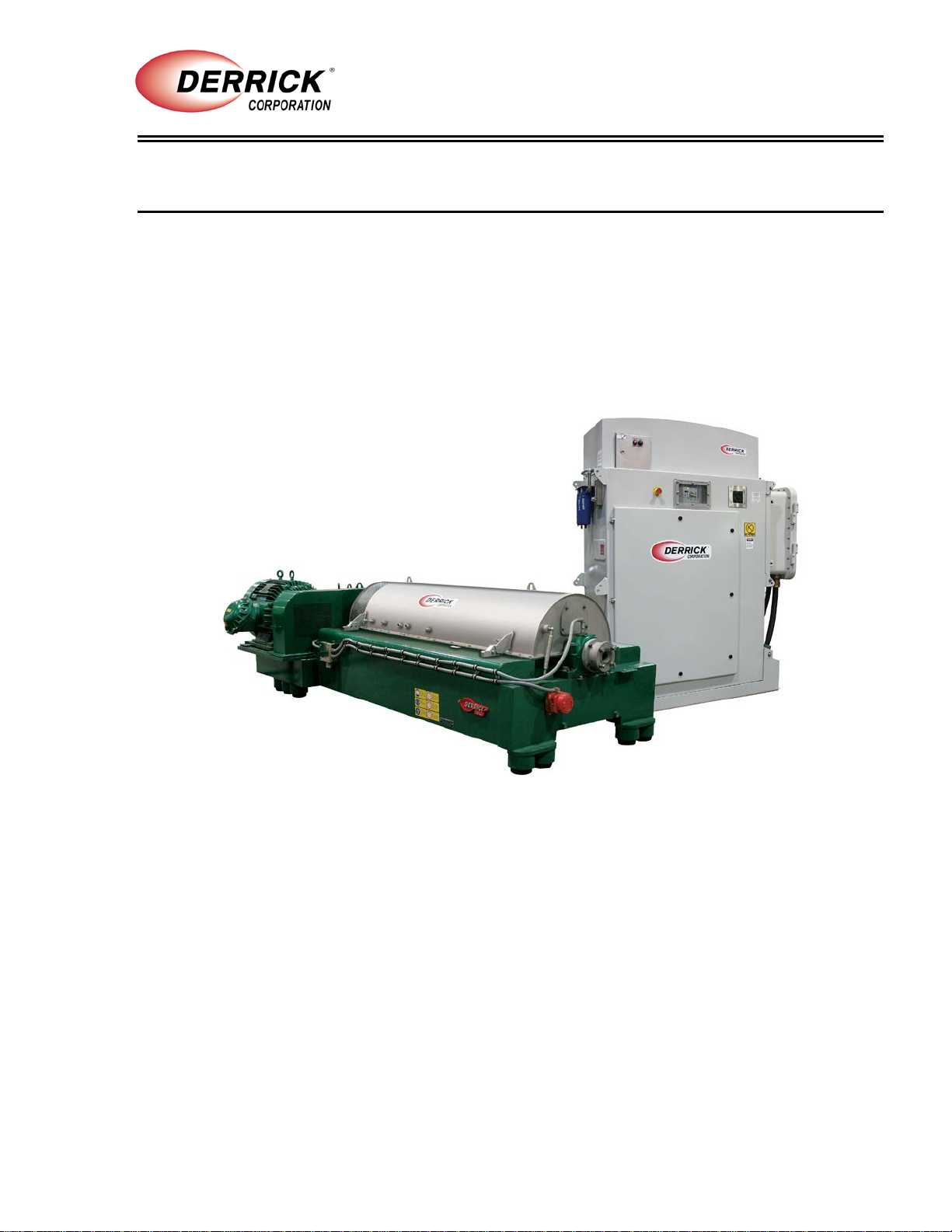
This manual provides instructions for installing and operating the DE-7200 Variable Frequency
Drive (VFD) centrifuge (Figure 1-1). The manual is divided into several sections to assist the user
in readily accessing the information. Instructions include description, theory of operation, safety,
installation, and maintenance. Reference drawings are provided to facilitate parts location and
ordering, as well as for understanding of equipment operation and assist in troubleshooting. The
manual also contains technical documentation provided by outside suppliers. These documents
cover components used in the centrifuge but not manufactured by Derrick.
Figure 1-1 DE-7200 Variable Frequency Drive (VFD) Centrifuge
SAFETY
Section 2 of this manual contains relevant safety information for both operation and maintenance
of this equipment. Be sure this information is read and understood by all personnel.
DO NOT operate the equipment if defective or faulty mechanical or electrical components are
detected.
SOUND EMISSION
Hearing protection is recommended when working on or near the centrifuge. Based on
measurements taken for technically comparable machinery, the centrifuge emits the following
airborne sound levels:
•A-Weighted Machine Surface-Averaged Sound Pressure Level at 1m – 90.9 dBA
•A-Weighted Machine Surface-Averaged Sound Power Level – 109.8 dBA
•C-Weighted Instantaneous Peak Sound Pressure Level – 111.4 dBC
INTRODUCTION
1-2 20 Sep 12
DE-7200VFDCentrifuge
EQUIPMENT USE
The DE-7200 VFD centrifuge is designed for removing low and high specific gravity solids from
slurries. In one type of processing, solids are removed and the liquid is returned for recirculation.
Alternatively, solids are returned to the active system and the liquid is discarded or processed by
a second centrifuge.
Derrick Corporation does not authorize any other use of this equipment. Intended usage of the
equipment includes compliance with the operating, maintenance, and safety procedures included
in this manual.
DESCRIPTION
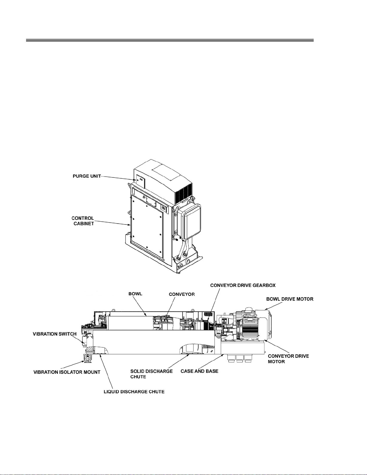
Major components of the centrifuge (Figure 1-2) consist of the rotating assembly (bowl, conveyor,
and conveyor drive gearbox), bowl and conveyor drive motors, control cabinet, purge unit,
vibration switch, and case and base. The following paragraphs describe these components.
Figure 1-2 DE-7200 VFD Centrifuge Major Components

INTRODUCTION
20 Sep 12 1-3
DE-7200VFDCentrifuge
Rotating Assembly
The rotating assembly consists of a cylindrically shaped, bowl, conveyor assembly, gearbox, and
related components. The bowl consists of a straight cylinder with a conical section at the solid
discharge end and a flat liquid bowl head at the opposite end. Openings are provided at both
ends to permit liquid and solid discharges. The bowl ends are supported by roller bearings having
grease fittings to facilitate periodic lubrication.
Bowl Assembly
The liquid bowl head at the liquid discharge end contains movable weir plates that permit manual
adjustment of the liquid level remaining in the bowl during rotation. Notched locking plates
adjacent to the weir plates facilitate precise adjustment. Although they are individually adjustable,
all plates must be set at the same level. The liquid level or pond depth, along with other factors,
helps determine the liquid content of the discharged solids. The conical bowl at the solid
discharge end forms an upward sloping beach, where solids are dried and continuously
discharged through the solid discharge ports. Replaceable inserts line the solid discharge ports to
minimize the rate of wear due to abrasive action.
Conveyor
The conveyor assembly is a hollow, cylindrical auger that receives the inlet slurry into its interior,
disperses it through feed nozzles to the bowl assembly, and transports the solids to the solids
discharge outlets. An electric motor connected to the input shaft of a three-stage planetary
gearbox turns the conveyor in the same direction as the bowl but at a higher rate of speed. The
outer housing of the gearbox is secured to the bowl, while the output shaft is directly connected to
the conveyor.
The differential speed setting on the control panel determines the conveyor speed in relation to
the bowl speed. This relationship remains consistent; as bowl speed is varied, the conveyor
speed varies commensurately but maintains the differential relationship. For example, a bowl
speed of 2000 RPM and a conveyor differential speed of 10 results in the conveyor rotating at a
rate of 2010 RPM.
The feed tube at the liquid discharge end directs inlet slurry into the interior of the conveyor, which
rapidly disperses the material through feed nozzles into the bowl. Replaceable inserts line each of
the six feed nozzles to minimize wear due to abrasive action. A roller bearing supports the
conveyor at the liquid bowl head, while at the solid end the conveyor is supported by the bearings
that are integral to the conveyor drive gearbox.
Conveyor Drive Gearbox
The conveyor drive gearbox is a three-stage planetary gearbox that rotates the conveyor at a
faster speed than the bowl assembly. The gearbox is mounted on, and consequently driven by,
the bowl assembly, Input and output shafts of the gearbox are supported by internal bearings. The
conveyor drive motor is coupled to the gearbox input shaft by a flexible coupling, which permits
compliance with slight alignment variations. The gearbox contains a gear system that transfers
rotation from the motor and bowl to the conveyor’s output shaft.
The input shaft end of the gearbox is supported by the solid end main bearing, while the output
end is secured to the bowl. The gearbox ratio of 49:1 turns the conveyor at a proportionally faster
rate than the bowl assembly. The control system ensures that the conveyor’s rotational speed
varies directly with bowl speed, maintaining a consistent differential relationship for solids
conveyance.
During an overload condition, excessive solids in the conveyor may overburden the motor or
gearbox, causing motor torque to increase and resulting in an overload alarm. If the conveyor’s

INTRODUCTION
1-4 20 Sep 12
DE-7200VFDCentrifuge
pre-set torque limit is reached, the control system automatically reduces the feed rate to enable
the conveyor to clear the excess solids. When the centrifuge is operating at the reduced feed rate,
the Operation screen displays a message to inform the operator of the modified status. Unless the
over-torque condition is removed, the centrifuge will be shut down automatically.
Conveyor Drive Gearbox (Cont’d)
If a sudden overload torque condition occurs, the conveyor drive clutch mechanically disengages
the conveyor drive motor to protect the gearbox (Figure 1-3) from damage. Following
disengagement, the centrifuge must be shut down and the clutch manually reset as follows:
•Align both clutch halves at one of the marks on the actuation ring and body.
•Insert a screwdriver blade between the actuation ring and adjustment nut in two places 180°
apart, and press ring back into engagement position.
Disengagement Re-Engagement
Figure 1-3 Conveyor Drive Clutch Operating Principles
Drive Motors
The centrifuge is configured to operate on a designated AC voltage supplied in three-phase, 50Hz
or 60Hz. The machine is operated by two inverter-duty, three-phase, explosion-proof electric
motors. A 150HP bowl drive motor is connected to the bowl assembly by a sheave and series of
drive belts, while a 60HP electric motor is directly coupled to the gearbox input shaft by a clutch
coupling. A protective guard covers the sheaves, drive belts, and conveyor drive clutch coupling
for personnel protection.
Control Cabinet
All electric power distribution and control system components required for centrifuge operation are
installed in the control cabinet. Incoming power energizes the VFDs that supply the varying output
power for operation and control of the bowl, conveyor, and pump drive motors. A step-down
transformer adjusts incoming power to the 115 to 120Vac power required for operation of the PLC
and operator control panel. The transformer also energizes the 24Vdc power supply that produces
the required DC power for operation of control system components. An Ethernet communication
network permits two-way data transfer between the PLC, VFDs, and operator control panel.
The cabinet air conditioner maintains a suitable environment for efficient operation of the VFDs
and other power and control components. The air conditioner is a conventional refrigeration unit
consisting of a compressor, condenser, and evaporator. The PLC uses the temperature input
provided by an RTD sensor to cycle the air conditioner on and off as required to maintain the
interior temperature within a range of 85°F to 95°F (29°C to 35°C). When the temperature rises to
INTRODUCTION
20 Sep 12 1-5
DE-7200VFDCentrifuge
the upper setpoint, the compressor and condenser motors are cycled on to provide cooling. Upon
reaching the low temperature setting, the air conditioner is shut down. The evaporator fan
operates continuously whenever the cabinet is energized to maintain a continuous flow of
conditioned air over cabinet components.
Purge System (Hazardous Environment Only)
For operation in a hazardous environment, the control cabinet is equipped with a purge system.
The purge system ensures that the cabinet interior remains free of potentially hazardous gases by
filling the cabinet with filtered air and maintaining positive pressure to exclude ambient gases.
During startup, before power is permitted to enter the cabinet, the cabinet purge system initiates a
16-minute rapid purge cycle at 16CFM. When the rapid purge cycle is completed, the purge
system automatically closes a switch that supplies power to the cabinet.
Following the rapid purge, the purge system maintains a positive pressure inside the cabinet to
exclude any potentially hazardous gases. Minimum pressure and purge flow sensors will shut
down power if the purge system is not maintaining satisfactory pressure in the cabinet. For further
details of purge system operation, refer to Section 4.
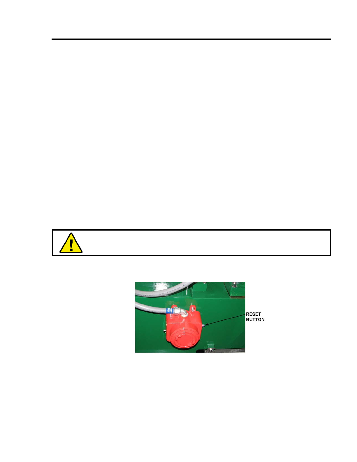
Vibration Switch
The vibration switch (Figure 1-4) is a safety device designed to protect personnel and equipment
by shutting down the centrifuge in case of excessive vibration. Normally, the switch contacts are
held closed by a magnetic latch. However, strong vibration or a shock of 2 Gs will overcome the
magnetic latch, causing the switch armature to break away from the normally closed position,
providing an input to the PLC. A reset button on the side of the switch must then be manually
pressed to close the contacts and re-engage the magnetic latch.
WARNING!
EXCEEDING THE 2 G SETTING CAN CAUSE INJURY TO
PERSONNEL OR DAMAGE TO EQUIPMENT.
DO NOT RAISE THE SETTING.
The vibration switch is mounted on the centrifuge base in an orientation that is most affected by
out-of-balance vibration of the bowl assembly. Clogging of the conveyor or worn bearings may
produce sufficiently high vibration to trip the switch.
Figure 1-4 Vibration Switch
Case and Base
When the top cover is closed, the case provides a sealed, protective enclosure that fully
surrounds the bowl assembly. The liquid discharge chute and solid discharge chute are installed
at the bottom of the lower case half. Mating baffles installed inside the top and bottom case halves
separate the solid and liquid phases. Bolts secure the top and bottom halves together; a gasket in
the bottom case half seals the two halves.

INTRODUCTION
1-6 20 Sep 12
DE-7200VFDCentrifuge
The case is bolted onto the welded steel base assembly, which contains mounting provisions for
the bearing pillow blocks. The base assembly supports the centrifuge components and contains
hollow rubber vibration isolators that engage with centering pins attached to the mounting
platform.
MECHANICAL OPERATION
The centrifuge receives slurry at the liquid discharge end of the machine. For best performance,
the slurry should be screened to 74 microns in vibrating screening machines before being fed to
the centrifuge. The slurry flows through a feed tube into the rotating bowl, where centrifugal force
separates liquid from the solids. Liquid flows out the liquid discharge connection, while solids are
conveyed to the solid discharge where a chute should be installed to receive the material.
G forces produced by the high-speed rotation of the cylindrical bowl separate solids from the feed
slurry. Centrifuge performance is based on three variable factors:
•G force exerted on the fluid - Gravitational force pulling fluid against the outside wall of the
centrifuge
•Retention time in the centrifuge - The longer the slurry remains in the centrifuge the smaller
the particle that can be separated
•Differential speed of conveyor - The faster the conveyor rotates, the wetter the solids and the
more solids that can be discharged
All three factors may be manipulated to alter the liquid and solids discharge. The G force is
adjusted by varying the bowl RPM. Retention time is controlled by adjusting the weir plates on the
liquid bowl head to change the pond depth (liquid level), and the conveyor differential speed
(difference between the bowl and conveyor speeds) may be adjusted on the operator control
panel. Bowl speed and differential speed are adjusted on the operator control panel, which
continuously displays current operating conditions.
All parameters other than pond depth may be changed quickly and easily while the centrifuge is
operating. These adjustments permit the operator to optimize efficiency in response to varying
feed conditions. Another method of altering the discharge results is to change the feed rate. For
best performance, the slurry should be screened to 74 microns in vibrating screen machines
before passing it to the centrifuge for processing.
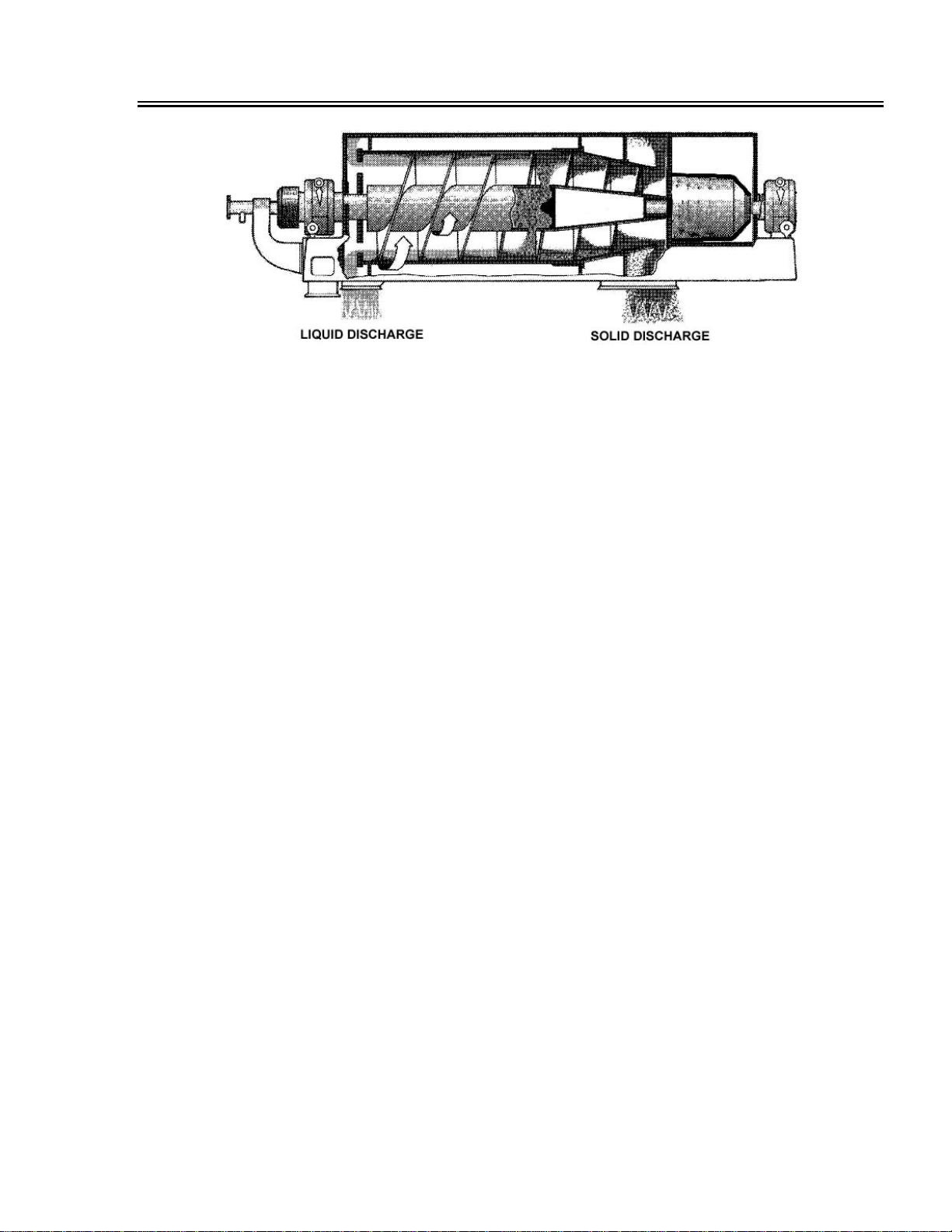
During centrifuge operation, slurry is pumped through the feed tube into the center of the rotating
conveyor (Figure 1-4), where it splashes against the feed accelerator. The slurry is accelerated to
the bowl speed and then dispersed out six feed nozzles on the periphery of the conveyor cylinder
into the bowl, which rotates at a slower speed than the conveyor.
As the slurry flows in the channels between the conveyor flights, the heavy particles settle at an
accelerated rate due to the G force imposed by the rotating bowl. Sand particles settle almost
instantly; then the finer, lighter particles settle. Particles that cannot be settled under the present
settings will be discharged with the liquid through the adjustable weirs on the liquid bowl head.
Liquid exiting the liquid bowl head is directed through the liquid discharge outlet.
The settled solids form a cake inside the bowl and are transported by the conveyor toward the
narrow end of the bowl (beach). As the solids travel across the beach, their free liquid film is lost
due to centrifugal squeezing and drainage, and they are discharged at high velocity through the
solid discharge ports on the bowl.
INTRODUCTION
20 Sep 12 1-7
DE-7200VFDCentrifuge
Figure 1-4 Centrifuge Operation
CONTROL SYSTEM
Centrifuge operation is supervised by a programmable logic controller (PLC) that interfaces with
the variable frequency drives (VFDs) supplying power to the bowl, conveyor, and feed pump drive
motors. Monitoring and control of the centrifuge may be performed locally or remotely. The
environmentally hardened PLC also offers short-term data storage and a high degree of operating
flexibility. The operator control panel mounted on the control cabinet facilitates communication
with the VFDs and provides real-time access to system operating characteristics. Through the
control panel, the operator may start the centrifuge, enter and adjust speed and torque limits for
bowl and conveyor, set feed rate, shut down the machine, and perform a variety of monitoring and
control functions.
Various inputs including main bearing temperatures, bowl speed, bowl and conveyor torques,
cabinet interior temperature, and vibration are transmitted to the PLC, which then responds with
corresponding outputs to govern centrifuge operation. Critical status information is displayed on
the control panel, as well as alarm and fault messages that inform the operator of any anomalies.
In case of a serious malfunction, the PLC automatically shuts down the centrifuge and displays an
explanatory message for the cause of the shutdown. In addition, the operator may shut down the
centrifuge at any time due to an emergency.
The feed pump is controlled by the PLC, which raises and lowers feed rate to accommodate the
maximum flow and torque limits set by the operator. Flow rate is increased within the set limit until
the torque limit setting is reached. Generally, for maximum throughput flow priority governs
centrifuge operation. However, the PLC defaults to torque priority upon reaching the torque limit
setting. Once torque priority is entered, the system will remain in torque priority even if feed
conditions cause the torque to fall, until flow priority is re-selected by the operator.
The system’s flexibility permits the PLC to raise the feed rate automatically to the set limit unless
the torque limit is reached by either the bowl or conveyor drive motor. Consequently, if feed slurry
properties change, causing the torque to rise, the PLC reduces the feed rate to stay under the
torque limit. The operator control panel displays which priority (flow or torque) is currently in force.

INTRODUCTION
1-8 20 Sep 12
DE-7200VFDCentrifuge
PRODUCT SUPPORT
Derrick Corporation offers 24-hour per day, 7-day per week product support. Product support
includes screen replacement / ordering information and repair / replacement parts and service for
the entire product line. Refer to the following table for the parts / service center nearest you.
PARTS SALES & SERVICE LOCATIONS
Colorado
Grand Junction - 970.241.2417
Louisiana
Broussard - 877.635.3354
New York - Corporate Headquarters
Buffalo - 716.683.9010
Oklahoma
Oklahoma City - 405.208.4070
Texas
Houston (Oilfield Headquarters) - 866.DERRICK (337.7425) 281.590.3003
North Texas (Bridgeport) - 405.208.4070
South Texas (Corpus Christi) - 361.299.6080
West Texas (Midland) - 405.397.4089
East Texas, Arkansas, and Louisiana - 281.546.1166
Wyoming
Casper - 307.265.0445
North Dakota
Williston - 701.572.0722
CONTACT INFORMATION
Location Telephone Facsimile (FAX)
E-Mail / Website
Derrick Corporation
590 Duke Road
Buffalo, New York 14225
USA
716.683.9010 716.683.4991 General Service Manager

SECTION 2 - SAFETY
30 Sep 13 2-1
DE-7200VFDCentrifuge
GENERAL
This section contains a summary of WARNINGS used in this manual and a list of material safety
data sheets (MSDSs) applicable to the equipment. The centrifuge has been designed to perform
the stated functions safely.
WARNINGS
All persons responsible for operation and maintenance of this equipment must read and
understand all safety information in this manual prior to operating and/or maintaining the
equipment. The safety warnings listed below are included in applicable procedures throughout
this manual.
Work Area
WARNING! ALWAYS BE AWARE OF WORK AREA HAZARDS
TO PROTECT
AGAINST
SLIPS, TRIPS, AND FALLS WHEN WORKING ON OR NEAR THIS
EQUIPMENT
.
WARNING! LOUD NOISE! WEAR
HEARING PROTECTION AT ALL TIMES
WHEN WORKING ON OR NEAR
THIS EQUIPMENT.
WARNING
! VISION HAZARD! SAFETY GLASSES MUST BE WORN AT ALL
TIMES WHEN WORKING ON OR NEAR THIS EQIPMENT TO PREVENT
SERIOUS EYE INJURY OR PERMANENT LOSS OF VISION.
Electrical Hazards
DANGER! HIGH VOLTAGE! SHUT DOWN, LOCK OUT, AND TAG OUT
ELECTRIC POWER, AND ENSU
RE THAT EQUIPMENT HAS STOPPED
ROTATING BEFORE WORKING ON THIS EQUIPMENT.
IF THE INPUT POWER
IS SPLIT, BE SURE THAT PHASING IS CORRECT BEFORE APPLYING
POWER TO CENTRIFUGE.
DANGER! USE EXTREME CAUTION WHEN OPERATING
CENTRIFUGE WITH
PURGE SYSTEM BYPASSED.
DANGEROUSLY HIGH VOLTAGE WILL BE
PRESENT IN CONTROL CABINET IF DOOR IS OPENED WHILE POWER IS
APPLIED.
WARNING!
DRIVE MOTOR MUST BE OPERATED AT THE DESIGNATED
SUPPLY VOLTAGE.
SAFETY
2-2 30 Sep 13
DE-7200VFDCentrifuge
WARNING! ELECTRICAL CONNECTIONS MUST BE MADE IN ACCORDANCE
WITH ALL APPLICAB
LE NATIONAL AND LOCAL CODES. FAILURE TO
COMPLY MAY RESULT IN AN UNSAFE CONDITION THAT COULD INJURE
PERSONNEL OR DAMAGE EQUIPMENT. ENSURE THAT ALL ELECTRICAL
AND CONDUIT CONNECTIONS ARE SECURE.
Equipment Handling
WARNING! TO ENSURE PROPER BALANCE AND ORI
ENTATION WHEN UNIT
IS RAISED AND PREVENT DAMAGE TO COMPONENTS, ATTACH LIFTING
SLING ONLY AT DESIGNATED LIFT POINTS. DO NOT ATTEMPT LIFTING BY
ATTACHMENT TO MOTOR OR ANY OTHER LOCATION.
WARNING! BE SURE THAT HANDLING DEVICES HAVE SUFFICIENT LIFTING
CAPAC
ITY TO SAFELY HANDLE THE WEIGHT OF THE EQUIPMENT.
WARNING! WHEN USING AN OVERHEAD LIFTING DEVICE, USE ALL FOUR
LIFTING POINTS PROVIDED.
WARNING! DO NOT REMOVE SHIPPING BRACKETS UNTIL EQUIPMENT HAS
BEEN POSITIONED AT FINAL INSTALLATION SITE.
WARNIN
G! WHILE OPENING AND CLOSING THE CENTRIFUGE COVER,
PERSONNEL MUST ENSURE THAT ALL BODY LIMBS AND ANY OTHER
ITEMS ARE CLEAR OF THE COVER GAP. TWO HANDS MUST BE USED,
WITH BOTH HANDS ON THE COVER HANDLES AT ALL TIMES. DERRICK
RECOMMENDS HAVING A HOIST AVAILA
BLE IF ADDITIONAL ASSISTANCE
IS DESIRED DURING THE OPENING/CLOSING PROCEDURE.
Operation
WARNING! ALL OPERATING AND MAINTENANCE PERSONNEL MUST READ
AND UNDERSTAND ALL SAFETY INFORMATION IN THIS MANUAL BEFORE
WORKING WITH THE EQUIPMENT.
WARNING! BE SUR
E THAT TOP COVER IS CLOSED AND SECURED AND
ALL PERSONNEL ARE CLEAR BEFORE STARTING MACHINE.
WARNING!
BEFORE STARTING CENTRIFUGE, BE SURE THAT ALL
SHIPPING BRACKETS HAVE BEEN REMOVED AND BEARING PILLOW
BLOCKS ARE PROPERLY TIGHTENED.
WARNING! ALWAYS AL
LOW MACHINE TO COAST TO A COMPLETE STOP
BEFORE OPENING
TOP COVER OR REMOVING GUARDS.
WARNING! DO NOT OPERATE CENTRIFUGE IF EXCESSIVE NOISE OR
VIBRATION DEVELOPS. ALWAYS CONFIRM THAT VIBRATION SWITCH AND
OTHER SAFETY DEVICES ARE FUNCTIONAL.
SAFETY
30 Sep 13 2-3
DE-7200VFDCentrifuge
WARNING! W
HILE OPENING AND CLOSING THE CENTRIFUGE COVER,
PERSONNEL MUST ENSURE THAT ALL BODY LIMBS AND ANY OTHER
ITEMS ARE CLEAR OF THE COVER GAP. TWO HANDS MUST BE USED,
WITH BOTH HANDS ON THE COVER HANDLES AT ALL TIMES. DERRICK
RECOMMENDS HAVING A HOIST AVAILABLE
IF ADDITIONAL ASSISTANCE
IS DESIRED DURING THE OPENING/CLOSING PROCEDURE.
Maintenance
DANGER! HIGH VOLTAGE! SHUT DOWN, LOCK OUT, AND TAG OUT
ELECTRIC POWER, AND ENSURE THAT EQUIPMENT HAS STOPPED
ROTATING BEFORE WORKING ON THIS EQUIPMENT.
WARNING! WHILE OPENING AND CLOSING THE CENTRIFUGE COVER,
PERSONNEL MUST ENSURE THAT ALL BODY LIMBS AND ANY OTHER
ITEMS ARE CLEAR OF THE COVER GAP. TWO HANDS MUST BE USED, WITH
BOTH HANDS ON THE COVER HANDLES AT ALL TIMES. DERRICK
RECOMMENDS HAVING A HOIST AVAILABLE IF ADDITIONAL ASSISTANCE
IS DESIRED DURING THE OPENING/CLOSING PROCEDURE.
DANGER! EXPLOSION HAZARD! BE CERTAIN THAT SURROUNDING
ATMOSPHERE IS CLEAR OF ALL POTENTIALLY EXPLOSIVE GASES BEFORE
OPENING CONTROL CABINET DOOR.
Storage
WARNING! CENTRIFUGE MAY BE DAMAGED BY STORING IN A HIGH
HUMIDITY ENVIRONMENT (GREATER THAN 50% RH). EQUIPMENT MUST BE
STORED IN A LOW-HUMIDITY ENVIRONMENT.
MATERIAL SAFETY DATA SHEETS (MSDS’S)
Material Safety Data Sheets (MSDSs) advise personnel of the properties and any possible
hazards associated with these materials. Emergency first aid procedures, special precautions,
emergency telephone number, and other relevant data are contained in the MSDSs. These
documents are prepared by the product manufacturers, which have sole responsibility for
accuracy of the information.
The MSDSs listed below apply to products used in the manufacture of the Derrick equipment.
Where shown, dates are current as of the publication date of this manual. The latest MSDSs may
be obtained from the product manufacturer.

SAFETY
2-4 30 Sep 13
DE-7200VFDCentrifuge
MSDS’S (CONT’D)
MATERIAL DESCRIPTION - WHERE USED MSDS / Date
Paints
PPG Dimetcote 302H Green 302F0250 Resin - Top Coat 1302H-5A / 04-11-10
PPG Dimetcote 302H Clear 302G0910 Cure - Top Coat 1302H-B / 01-21-10
PPG PSX 700 Neutral Tint Resin - Undercoat
PX700T3 / 02-28-08
PPG PSX 700FD Cure - Undercoat PX700FD-B / 01-11-07
Lubricants
Shell Albida EP2 - Main & Conveyor Bearings 57089L / 06-18-09
Exxon Mobil SHC 629 - Conveyor Drive Gearbox Mobil SHC 629 / 01-13-09
Exxon Mobil Polyrex EM - Bowl & Conveyor Drive Motors Polyrex EM / 06-01-05
Sealant
Loctite 243 Anti-Seize Lubricant - Fasteners
76764 / 05-27-09
Table of contents


