- 7 -
4
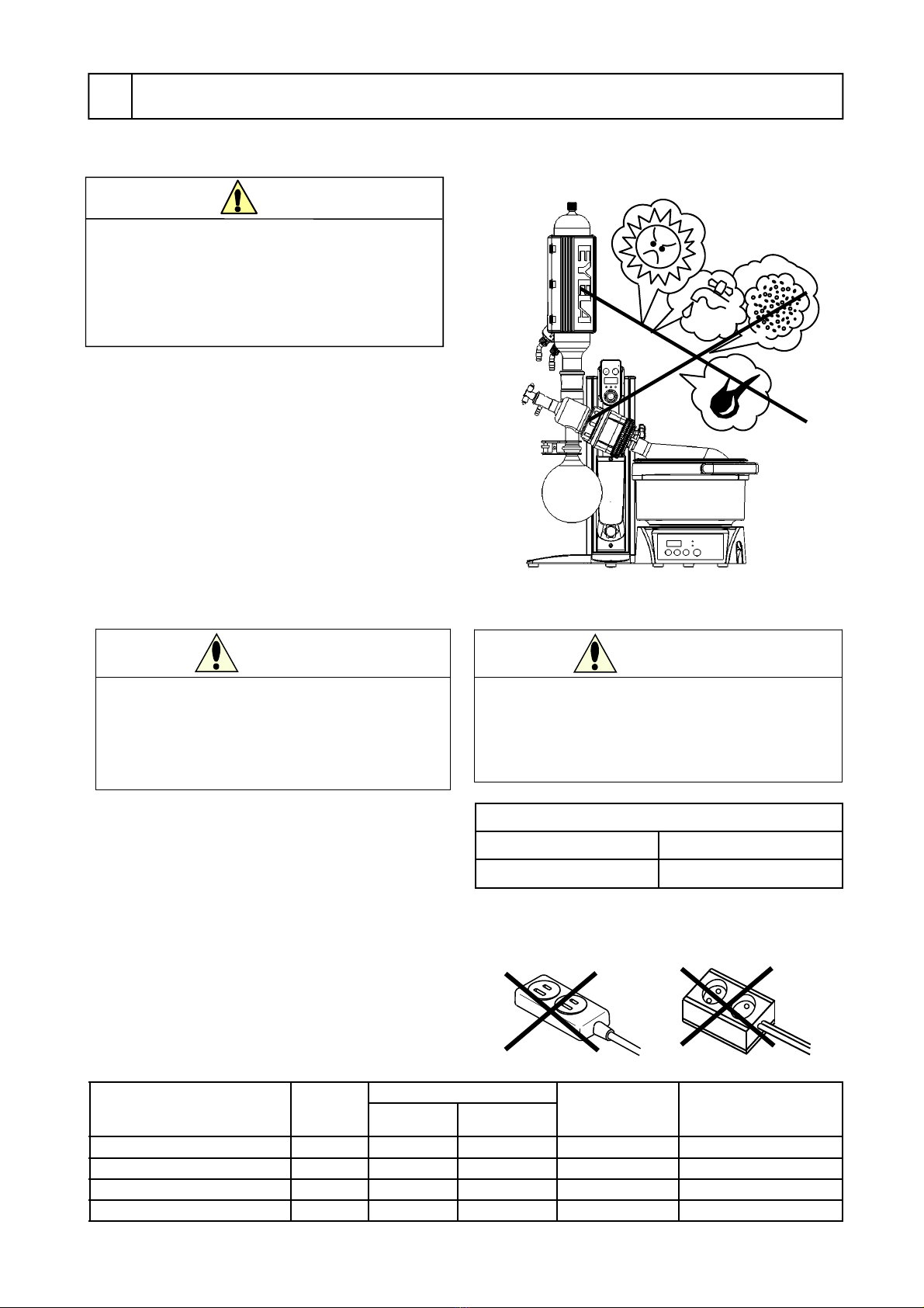
Warning
Do not use the branching socket
or table tap.
Burn-out of the cable or a fire may result from over
current.
Power supply to connect
Voltage Capacity
AC115~240V 15A
(1) Check the product type as well as the voltage, phase,
and capacity of power supply to be connected.
Power supply to be connected to the product is as
shown in the right.
(2) Check the receptacle of installation place.
※Do not connect the power plug yet ※First make
sure that the sheath of the power cord is not
damaged. Otherwise, an electric shock may result.
※Use the supplied power cord only.
A fire or an electric shock may result from
insufficient capacity.
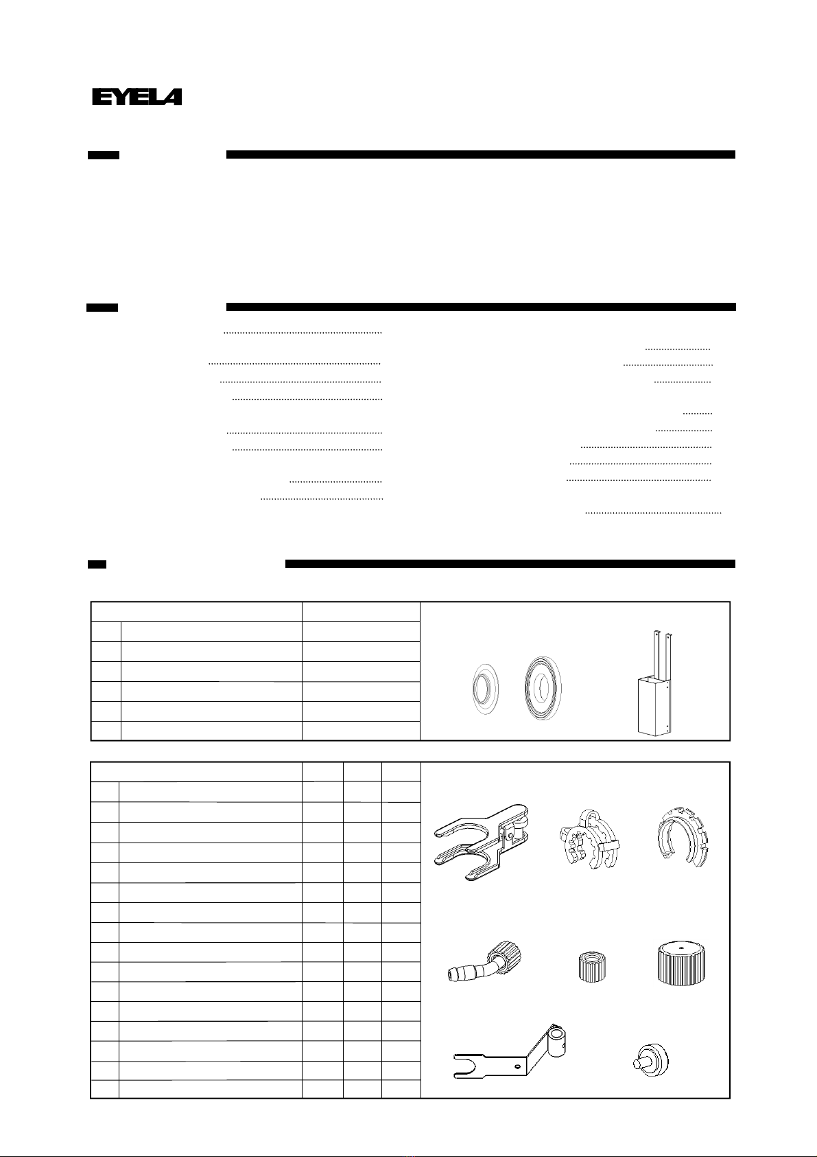
Power cord specification
Name Cord No Cable Section area of
electric wire(AWG) Areas supported
Length O.D.
115V Power code A type 267699 Approx.2.0m Approx.5.8mm 0.8mm2(AWG18) North America
220V Power code O type 267698 Approx.1.8m Approx.5.7mm 0.75mm2(AWG18) China
220~240V Power code B type 267695 Approx.2.0m Approx.5.6mm 0.75mm2(AWG18) U.K., India
220~240V Power code C type 267697 Approx.2.0m Approx.5.6mm 0.75mm2(AWG18) Europe
※Never use a branching socket or a table tap for
connecting to the power supply.
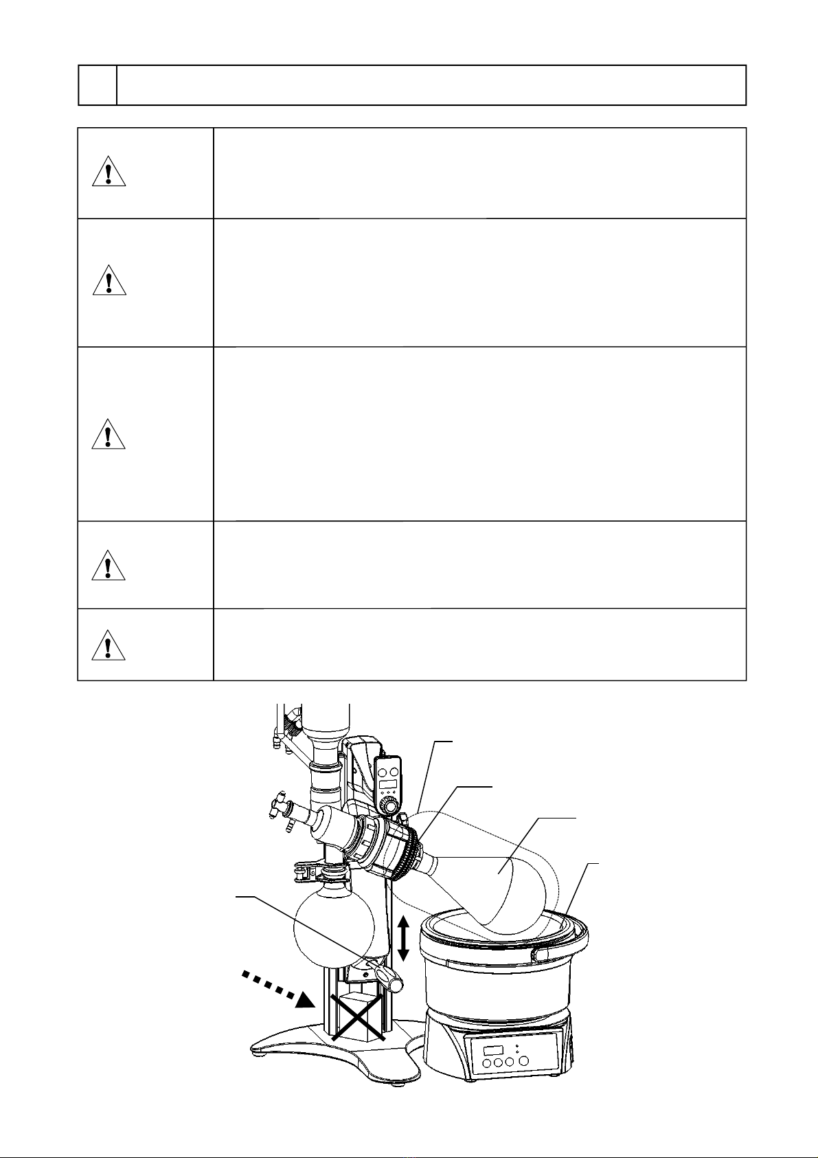
4-1 Installation environment
Select a place that meets the conditions below
for installing this product:
Never install the product in a
potentially hazardous atmosphere.
The product is not explosion-proof. Use in a
potentially hazardous atmosphere may cause a fire
or other accidents.
Warning
●Place free of flammable gas, liquid, or solid
materials in the vicinity of the product.
●Place where the ambient temperature can be kept
within a range of 5~35℃.
●Place free from condensation
●Place with less humidity and free from splashing
water
●Place with minimum dust
●Place free from direct sunshine
●Place where airy or well-ventilated
●Level, stable, and firm place
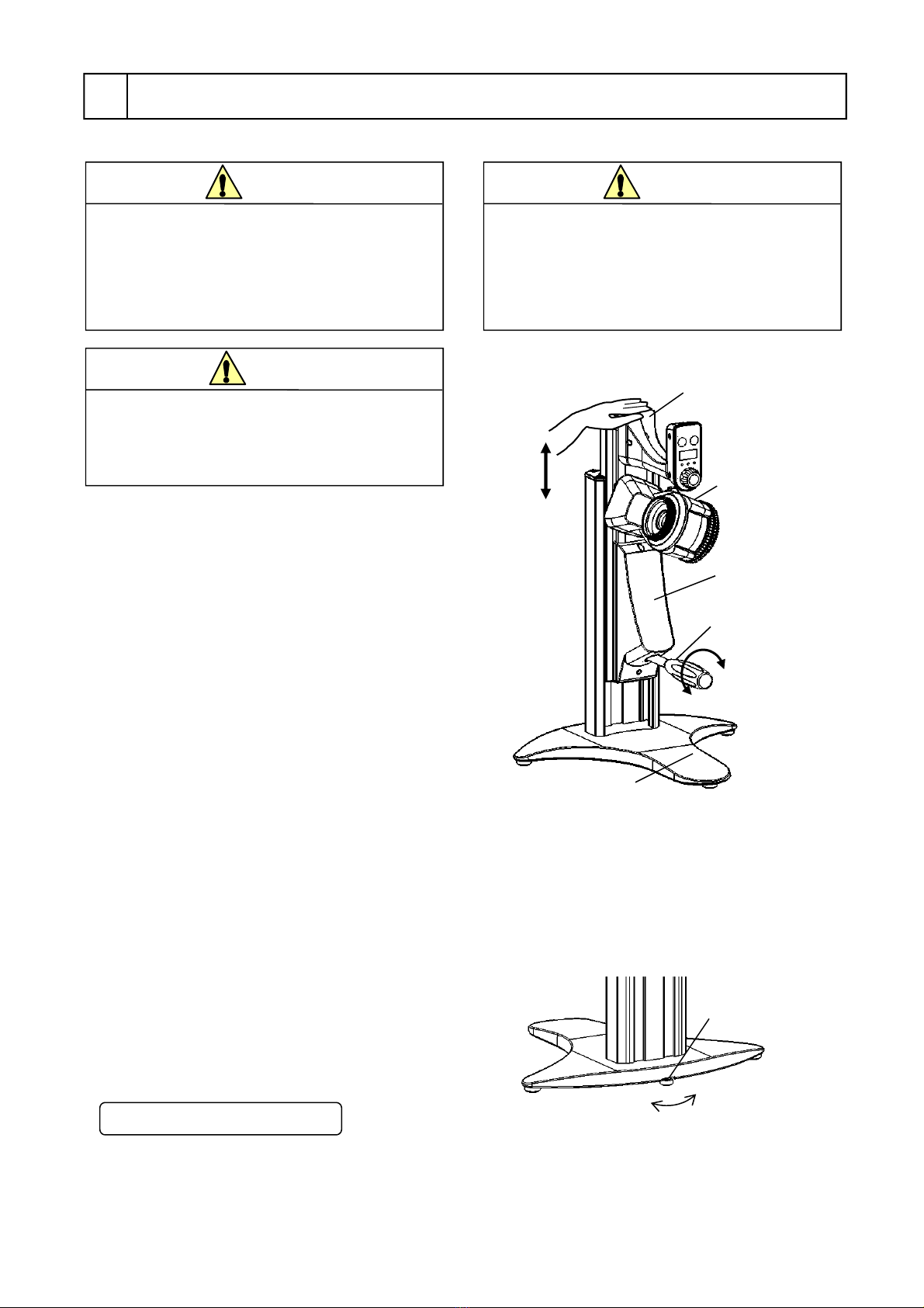
Installation
Warning
Confirm the voltage, phase, capacity,
and the type of receptacle of power
supply.
Wrong connection of power supply may cause fire or
electric shock
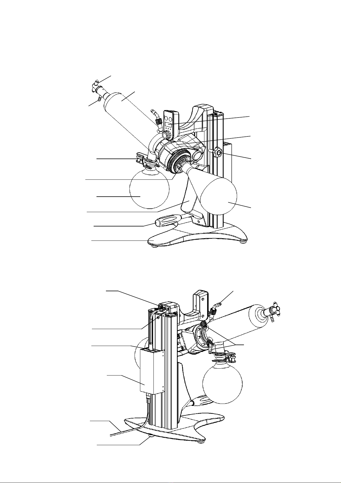
4-2 Connecting utilities