Designers Fountain 52TB3L5-NI User manual
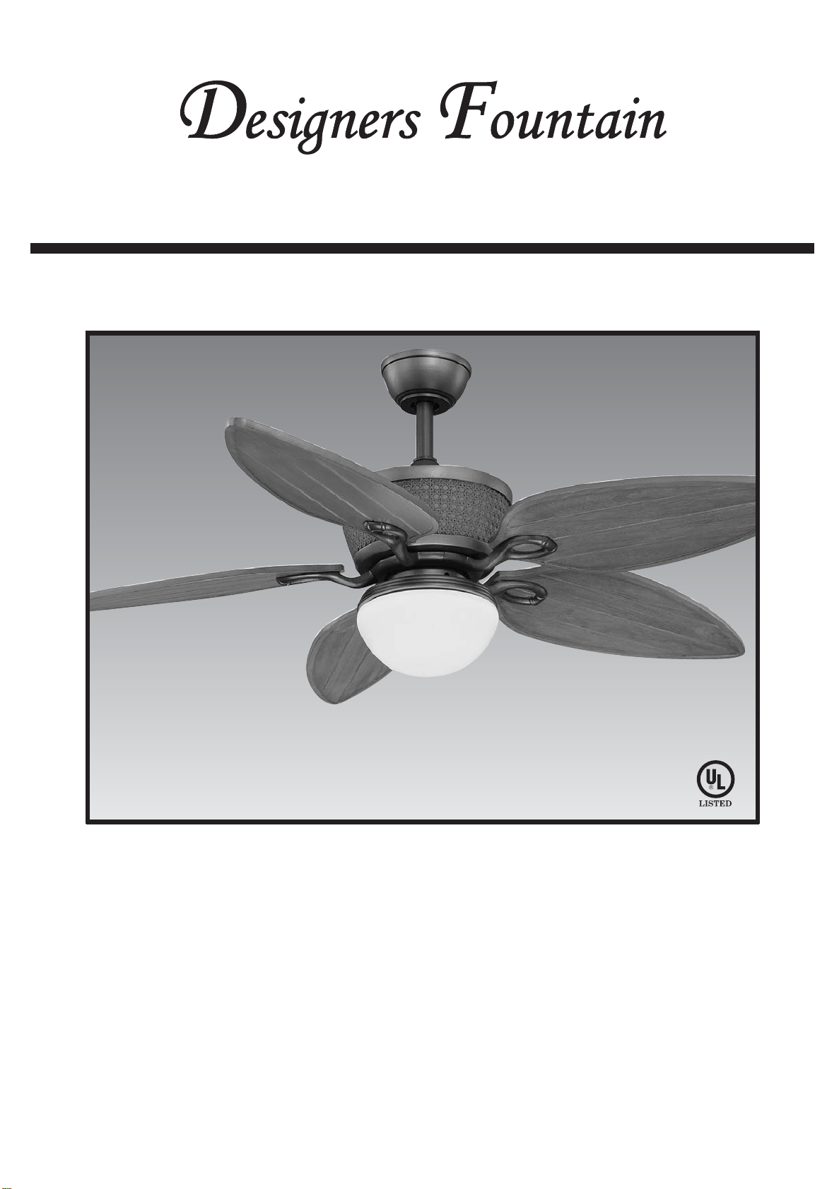
FAN RATING AC 120V. 60Hz UL LISTED MODEL : AC-552OD
MODEL: 52TB3L5-NI
CEILING FAN OWNER'S MANUAL
Distinctive Lighting and Ceiling Fans
READ AND SAVE THESE INSTRUCTIONS
FOR CEILING FAN PARTS AND SERVICE,
CALL 1-877-902-5588
1. To reduce the risk of electric shock,
insure electricity has been turned off
at the circuit breaker or fuse box
before beginning.
2. All wiring must be in accordance with
the National Electrical Code and local
electrical codes. Electrical installation
should be performed by a qualified
licensed electrician.
3. WARNING: To reduce the risk of
electrical shock and fire, do not use
this fan with any solid-state fan speed
control device.
4. WARNING: To reduce the risk of
personal injury, use only the two steel
screws (and lock washers) provided
with the outlet box for mounting to
the outlet box. Most outlet boxes
commonly used for the support of
lighting fixtures are not acceptable for
fan support and may need to be
replaced, consult a qualified electrician
if in doubt.
5. The outlet box and support structure
must be securely mounted and
capable of reliably supporting a
minimum of 50 pounds. Use only UL
Listed outlet boxes marked "FOR FAN
SUPPORT".
6. WARNING: Use only with light kit
marked "Suitable for Use in Wet
Locations".
7. The fan must be mounted with a
minimum of 7 feet clearance from the
trailing edge of the blades to the floor.
8. Do not operate reversing switch while
fan blades are in motion. Fan must be
turned off and blades stopped before
reversing blade direction.
9. Avoid placing objects in the path of the
blades.
10. To avoid personal injury or damage to
the fan and other items, be cautious
when working around or cleaning the
fan.
11. Do not use water or detergents when
cleaning the fan or fan blades. A dry
dust cloth or lightly dampened cloth
will be suitable for most cleaning.
12. After marking electrical connections,
spliced conductors should be turned
upward and pushed carefully up into
outlet box. The wires should be spread
apart with the grounded conductor
and the equipment-grounding
conductor on one side of the outlet
box.
13. Electrical diagrams are reference only.
Light kit that are not packed with the
fan must be UL Listed and marked
suitable for use with the model fan you
are installing. Switches must be UL
General Use Switches. Refer to the
Instructions packaged with the light
kits and switches for proper assembly.
1
1. SAFETY RULES
WARNING
TO REDUCE THE RISK OF FIRE,
ELECTRIC SHOCK OR PERSONAL
INJURY, MOUNT FAN TO OUTLET BOX
MARKED "ACCEPTABLE FOR FAN
SUPPORT".
WARNING
TO REDUCE THE RISK OF PERSONAL
INJURY, DO NOT BEND THE BLADE
BRACKETS (ALSO REFERRED TO AS
FLANGES) DURING ASSEMBLY OR
AFTER INSTALLATION. DO NOT
INSERT OBJECTS IN THE PATH OF THE
BLADES.
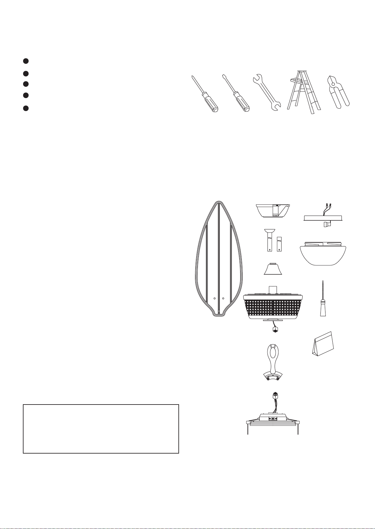
3. PACKAGE CONTENTS
Philips screw driver
Blade screw driver
11 mm wrench
Step ladder
Wire cutters
2
2. TOOLS AND MATERIALS
REQUIRED
Unpack your fan and check the contents.
You should have the following items;
a. Blade set (5)
b. Hanger bracket assembly
c. Ball/downrod assembly (1)
& extra downrod (1)
d. Coupling cover
e. Fan motor assembly
f. Set of blades bracket (5)
g. Switch housing
h. Light plate
i. Glass shade
i. Pull chain and fobs (2)
k. Package hardware
1) Mounting hardware :
screws (2), lock washers (2),
star washers (2), wire nuts (3),
wood screws (2), washers (2)
2) Blade attachment hardware:
screws (16), rubber washers (16)
3) Balance Kit
ab
c
d
e
f
g
h
i
j
k
WARNING
DO NOT INSTALL OR USE FAN
IF ANY PART IS DAMAGED OR MISSING.
CALL TOLL FREE 1-877-902-5588.

4. MOUNTING OPTIONS
If there isn't an existing UL listed mounting
box, then read the following instructions.
Disconnect the power by removing fuses
orturningoffcircuitbreakers.
Secure the outlet box directly to the
building structure. Use appropriate
fasteners and building materials. The
outlet box and its support must be able to
fully support the moving weight of the fan
(at least 50 lbs). Do not use plastic outlet
boxes.
Figures 1,2 and 3 are examples of different
waystomounttheoutletbox.
Note: You may need a longer downrod to
maintain proper blade clearance when
installingonasteep,slopedceiling.(Fig.3)
Tohang your fan where thereis an existing
fixture but no ceiling joist, you may need
an installation hanger bar as shown in
Figure4.
Outlet box
Outlet box
Figure 1
Figure 3
Figure 4
Outlet box
Figure 2
3
Provide strong
support
Recessed
outlet box
Ceiling
hanger
bracket
* Angled ceiling
maximum
27° angle
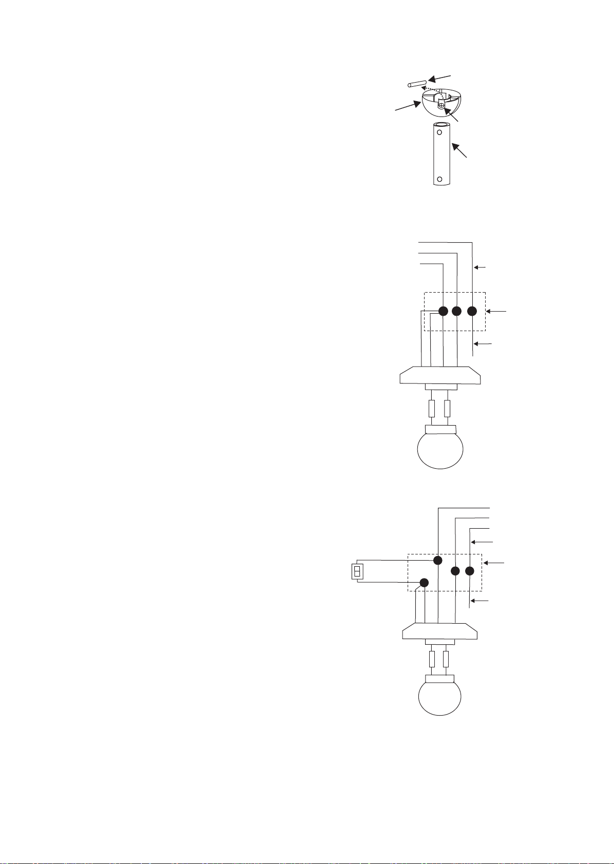
REMEMBER to turn off the power. Follow
the steps below to hang your fan properly:
Step 1. Remove the decorative canopy
bottom cover from the canopy by turning
the cover counter clockwise.(Fig. 5)
Step 2. Remove the hanger bracket from
the canopy by loosening the two screws
on the bottom of the hanging bracket a
half turn from the screw head and turning
the canopy counter clockwise.(Fig, 5)
Step 3. Pass the 120-volt supply wires
through the center hole in the ceiling
hanger bracket as shown in Fig. 6.
Step 4. Secure the hanger bracket to the
ceiling outlet box with the screws and
washers provided with your outlet box.
Step 5. Remove the hitch pin, lock pin and
set screws from the top of the motor
assembly.
Step 6. Route wires exiting from the top
of the fan motor through the coupling
cover, canopy cover, canopy and then
through the ball / downrod. (Fig. 7)
NOTE: Do not install the coupling cover if
you plan to use the 4" downrod.
Step 7. Align the holes at the bottom of
the downrod with the holes in the collar
on top of the motor housing (Fig.7).
Carefully insert the hitch pin through the
holes in the collar and downrod. Be
careful not to jam the pin against the
wiring inside the downrod. Insert the
locking pin through the hole near the end
of the hitch pin until it snaps into its
locked position, as noted in the circle inset
of Fig. 7.
Step 8. Tighten two set screws on top of
the fan motor firmly. (Fig. 7)
Step 9. Place the downrod ball into the
hanger bracket socket. (Fig. 8)
5. HANGING THE FAN
4
Figure 5
Ceiling
canopy
Canopy
cover
Mounting screws
(supplied with
electrical box)
Hook
Ceiling
mounting
plate
UL Listed
electrial
box
Figure 6
Figure 7
Figure 8
120V Wires
Washers
Registration slot
Downrod
Canopy
Set screws
Hitch pin Lock pin
Canopy cover
Hanger bracket
Coupling cover
*Omit coupling
cover when using
the minimum-length
downrod
5
6. MAKE THE ELECTRIC
CONNECTIONS
Remember to disconnect the power.
Follow the steps below to connect the fan
to your household wiring. Use the wire
connecting nuts supplied with your fan.
Secure the connectors with electrical tape.
Make sure there are no loose strands or
connections.
Step 1 Connect the fan supply (black) wire
andlightsupply(blueandorangr)wiretothe
black household supply wire as shown in
Figure10.
Step 2. Connect the neutral fan (white)
wire to the white neutral household wire.
Step 3 Connect the fan ground wire
(green) to the household ground wire.
Step 4 After connecting the wires, spread
them apart so that the green and white
wires are on one side of the outlet box and
the black and the blue wires are on the
other side.
Step 5 Turn the connecting nuts upward
and push the wiring into the outlet box.
Figure 10
Figure 9
Figure 11
WH
BLUE
BLK
ORANGE
WH
GRN
WIRING
BOX
GROUND TO
MOUNTING
BRACKET
OR DOWNROD
BLUE
BLK WH
WH
FAN
LIGHT
POWER LINES 120V
BLK
GREEN GROUND
BLK
WIRING
BOX
GROUND TO
MOUNTING
BRACKET
OR DOWNROD
POWER LINES 120V
WH
BLUE
BLK
WH
FAN
LIGHT
BLK
BLUE WH
WH
LIGHT
SWITCH
GREEN GROUND
ORANGE
CHANGINGTHE DOWNROD (OPTIONAL)
NOTE: Your fan comes with a 6" downrod
attached to the hanger ball. In addition
you have been provided with a 4"
downrod to use if desired. If you choose to
usethe4"downrod, performthefollowing
steps:
1. Remove the hanger ball from the 6"
downrod by loosening the set screw at the
top of the downrod which holds the
hangerballtothedownrod.(fig.9)
2. Slide the hanger ball down the downrod
andremovethesupportpin.(fig.9)
3. Insert the support pin in the holes at the
top of the 4" downrod and slide the
hanger ball up the 4" downrod. Make sure
the support pin is properly seated in the
groovesinthetopofthehangerball.
4.Tightenthesetscrewfirmly.
Downrod
Cross pin
Hanger
ball Set screw
6
7. FINISHING THE
INSTALLATION
Step 1. Tuck connections neatly into
ceiling outlet box.
Step 2. Slide the canopy up to ceiling
and over the two screws on hanger
bracket. Rotate canopy clockwise, next,
while holding the canopy with one hand,
slide the canopy cover over the screws
and rotate clockwise until tight. Note:
adjust the canopy screws as necessary
until the canopy and canopy cover are
snug. (Fig.13)
Warning: Make sure tab at bottom of
hanger bracket is properly seated in
groove of hanger ball before attaching
canopy to bracket. Failure to properly seat
tab in groove could cause damage to
electrical wiring.
Figure 13
Figure 12
Figure 14
Outlet box
Hanger
bracket
Canopy
Canopy cover
Screws
8. ATTACHING THE FAN
BLADES
Caution: Remove 5 rubber packing
mounts and discard before installation.
Step 1 Attach the blade to the blade
bracket using the screws and rubber
washers as shown in Figure 14. Start screw
into bracket. Repeat for the two remaining
screws.
Step 2 Tighten each screw. Make sure the
blade are straight.
Step 3 Fasten blade assembly to motor
using the screws supplied. (Fig. 14)
GROUND TO
MOUNTING
BRACKET
OR DOWNROD
POWER LINES 120V
GREEN
GROUND
WIRING
BOX
BLK
WH
BLUE
BLK
WH
FAN
LIGHT
WH
WH
BLUE
BLK
LIGHT FAN
ORANGE
Figures 11 and 12 illustrate the wiring
connections for optional wall control (The
wire color out of wall control may vary, see
wall control's installation manual for
correct wire connections.)
WARNING: TO REDUCE THE RISK OF FIRE,
ELECTRIC SHOCK, OR OTHER PERSONAL
INJURY. MOUNT FAN ONLY ON AN OUTLET
BOX OR SUPPORTING SYSTEM MARKED
ACCEPTABLEFOR FAN SUPPORT.
Screws Blade
Set of blades bracket
Screws
Rubber
washers
7
Figure 15
Figure 16
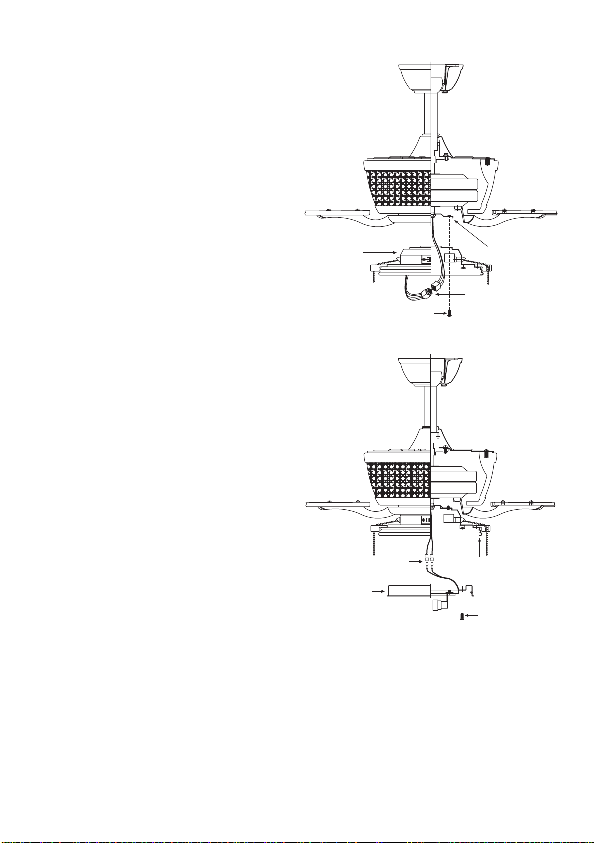
9.INSTALLATINGTHE
SWITCHHOUSING
Step 1. Remove 1 of the 3 screws from
the mounting ring and loosen the other
2 screws. (Do not remove)
Step 2. While holding the switch
housing under your fan, snap together
the wire connection plugs .
Step 3. Place the key holes on the
switch housing over the 2 screws
previouslyloosened from the mounting
ring,turnswitch housing untilitlocksin
place at the narrow section of the key
holes. Secure by tightening the 2
screwspreviouslyloosenedandtheone
previously. (Fig. 15)
10.INSTALLATINGTHE
LIGHTPLATE
NOTE: Before starting installation,
disconnectthe power by turning off the
circuit breaker or removing the fuse at
fuse box. Turning power off using the
fan switch is not sufficient to prevent
electric shock.
Step 1. Remove 1 of the 3 screws from
the switch housing and loosen the
other 2 screws. (Do not remove)
Step 2. Raise and hold the light plate
close to the switch housing and
proceed to do the wire connections.
Connect the white wire connectors
from the light plate and fan, follow the
same procedure with the blue and
black wire connectors. (Fig. 16)
Step 3. Place the key holes on the light
plate over the 2 screws previously
loosened from the switch housing, turn
light plate until it locks in place at the
narrow section of the key holes. Secure
by tightening the 2 screws previously
loosened and the one previously. (Fig.
16)
Connector
plug
Screws
Switch
housing
Mounting ring
Light plate
Wire connection
plugs Switch
housing
Screws
8
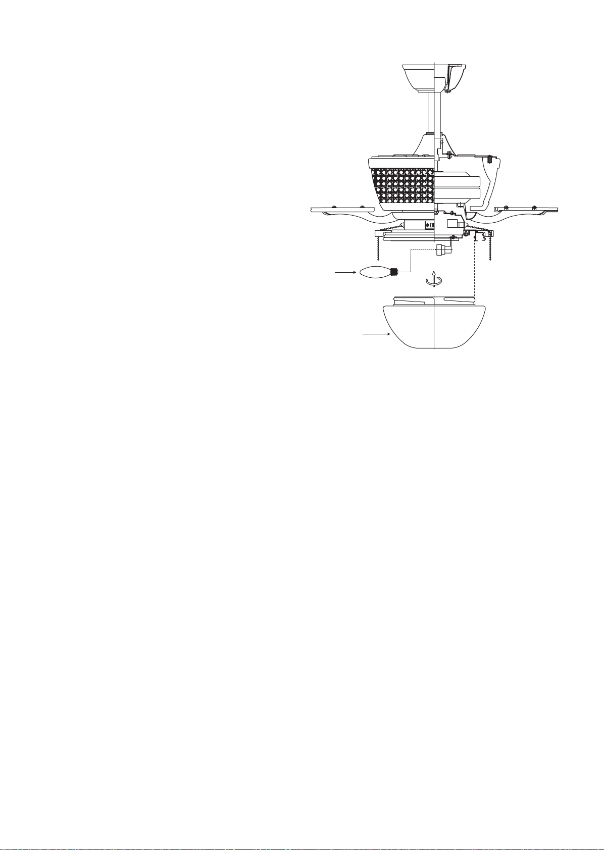
Figure 17
11. INSTALLING THE
LIGHT BULBS & GLASS
SHADE
1. Install 3 x 40W candelabra bulbs (not
included). (Fig. 17)
2. Raise light kit up against bottom of
fan housing and secure it to fan by
twisting glass clockwise until snug.
DO NOT OVERTIGHTEN. (Fig. 17)
3. Restore power and your light kit is
ready for operation.
Bulbs
Glass shade

9
Figure 18
Figure 19
12. OPERATING YOUR FAN
NOTE: Wait for fan to stop before
changing the setting of the slide switch.
Turn on the power and check the
operation of your fan. There are two
pull chains available in your fan:
1. 3-speed pull chain- it controls the fan
speed as follows: 1 pull- High, 2 pulls-
Medium,3pulls- Low, and4pulls-Off.
Speed settings for warm or cool
weather depend on factors such as
the room size, ceiling height, number
of fans, and so on.
2. Light kit pull chain- it controls the
light kit in "ON" or "OFF".
The slide switch controls directions:
forward (switch left ) or reverse (switch
right ).
Warm weather - (Counter-Clockwise
direction) A downward air flow creates
a cooling effect.(Fig. 18) This allows you
to set your air conditioner on a higher
setting without affecting your comfort.
Cool weather- (Clockwise direction) An
upward airflow moves warm air off the
ceiling area. (Fig. 19) This allows you to
set your heating unit on a lower setting
without affecting your comfort.

10
Problem
Fan will not start.
Fan sounds
noisy.
Fan wobble.
Solution
1. Check circuit fuses or breakers.
2. Check line wire connections to the fan and switch wire connections
in the switch housing.
CAUTION: Make sure main power is off.
1. Make sure all motor housing screws are snug.
2. Make sure the screws that attach the fan blade bracket to the motor
hub are tight.
3. Make sure wire nut connections are not rubbing against each other
or the interior wall of the switch housing.
CAUTION: Make sure main power is off.
4. Allow a 24-hour "breaking-in" period. Most noise associated with a
new fan disappear during this time.
5. If using an optional light kit, make sure the screws securing the
glassware are tight. Check that the light bulb is also secure.
6. Some fan motors are sensitive to signals from solid-state variable
speed controls. If you have installed this type of control, choose and
install another type of control.
7. Make sure the upper canopy is a short distance from the ceiling. It
should not touch the ceiling.
1. Check that all blade and blade arm screws are secure.
2. Most fan wobbling problems are caused when blade levels are
unequal. Check this level by selecting a point on the ceiling above
the tip of one of the blades. Measure this distance. Rotate the fan
until the next blade is positioned for measurement. Repeat for each
blade. The distance deviation should be equal within 1/8".
3. Use the enclosed Blade Balancing Kit if the blade wobble is still
noticeable.
4. If the blade wobble is still noticeable, interchanging two adjacent
(side by side) blades can redistribute the weight and possibly result
in smoother operation.
WARNING: TO REDUCE THE RISK OF PERSONAL INJURY, DO NOT BEND
THE BLADE ARM WHILE INSTALLING, BALANCING THE BLADES, OR
CLEANING THE FAN. DO NOT INSERT FOREIGN OBJECTS BETWEEN
ROTATING FAN BLADES.
13. TROUBLESHOOTING
Table of contents
Other Designers Fountain Fan manuals

Designers Fountain
Designers Fountain 52CG2L5-NI User manual

Designers Fountain
Designers Fountain 52SH4L5-PW User manual

Designers Fountain
Designers Fountain 52LA2L5-AVW User manual

Designers Fountain
Designers Fountain 52DH4L5-BN User manual

Designers Fountain
Designers Fountain 54GP2L5-VBG User manual

Designers Fountain
Designers Fountain 52ST3L5-BN User manual

Designers Fountain
Designers Fountain 52CW2L5-GM User manual

Designers Fountain
Designers Fountain 52SR3L5-DW User manual


