DesignHouse 594812 User manual
SINGLE HANDLE
SHOWER TRIM WITH VALVE
Models
Your new Design House trim will give you years of trouble free performance. Thank you for
choosing our product for your home. Please read all of these instructions carefully before
installing your new trim.
When installing your new trim, hand tighten the connector nuts, then use one wrench to
anchor the fitting and a second wrench to tighten the nut one additional turn. Connections that
are too tight will reduce the integrity of the system.
Wrap threaded connections (except aerator thread in spout or where o-ring or rubber sealant
are present) with Teflon tape available from your local hardware or plumbing supply store.
Always wrap in a clockwise direction.
IMPORTANT POINTS
SAFETY TIPS
ALWAYS protect your eyes with safety glasses.
Helpful tools to install this valve:
Teflon Tape
(2) Crescent Wrenches
Basin Wrench
Flashlight
Faucet Supply Tubes
Silicon Sealer
INSTALLATION PROCEDURE
5. Flushing the water outlets and checking for
leaks
Place the handle (1) on the valve body (2)
inverter and turn the handle (1) to the full on
mixed position. Turn on the hot and cold water
supply lines and allow the water to flow from
the outlets for one minute, or until all foreign
matter has been flushed out. Check for leaks.
Shut off the water at the faucet and supply
lines. Remove the handle (1).
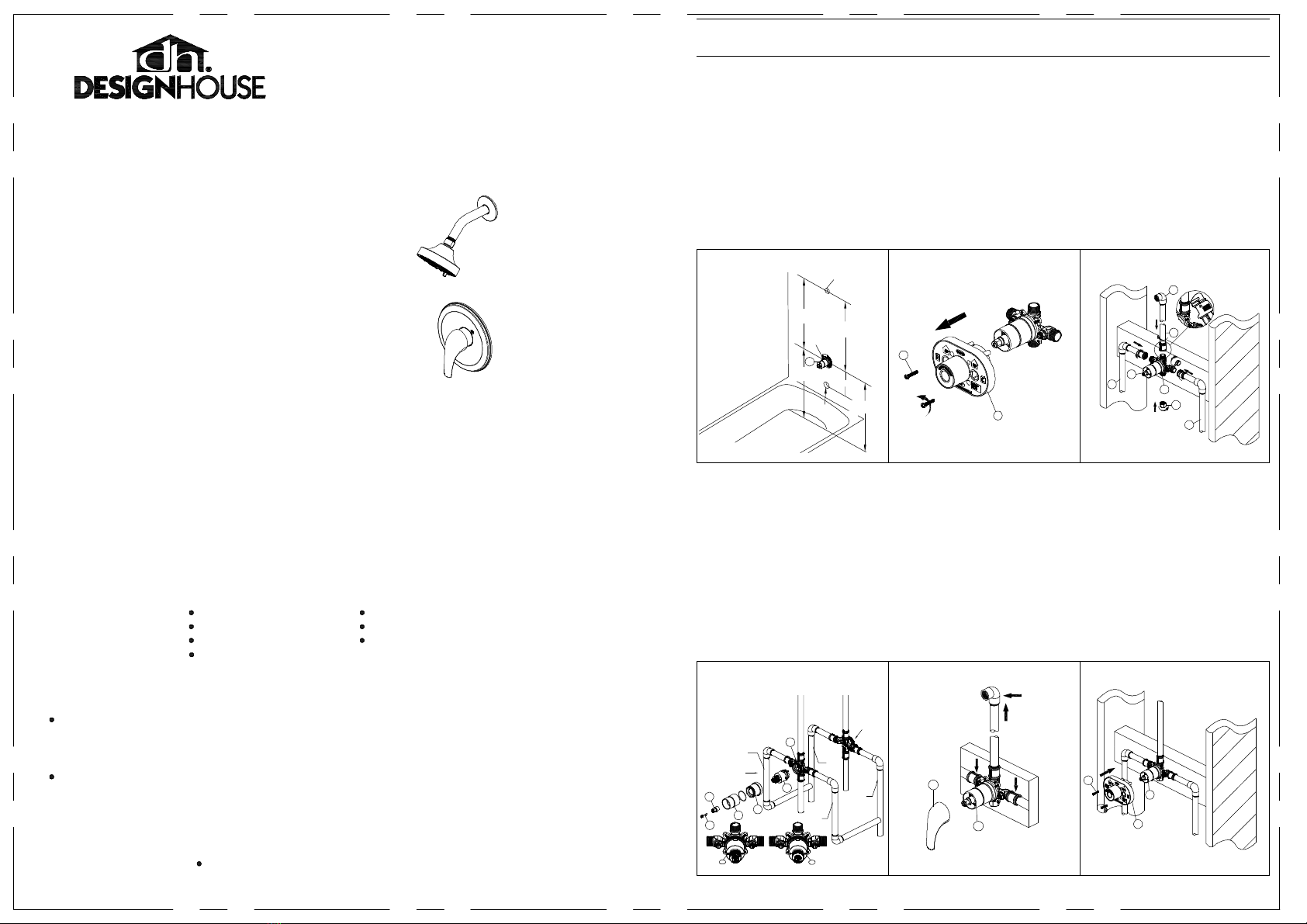
4. Back to back installation
If the hot and cold inlets are reversed (hot on right
and cold on left), remove the screw (1), inverter
(2), sleeve (3), and bonnet (4) from the valve body
(5) with reversed supply connections. Rotate the
cartridge (6) 180°, so H appears on the right.
Install the cartridge making sure that the key is
fully engaged with the slot in the valve body (5).
Slide the bonnet (4) over the cartridge (6) and
thread them onto the valve body (5). Hand tighten
securely. Reassemble the sleeve (3), inverter (2)
and screw (1). If you are not making a reverse or
back to back installation, skip this step and
continue with the step 5.
NOTE: Never install the valve body (5) upside
down!
23
1. Preparing for installation
A. Shut off the water supply to the tub and shower.
B. Verify that the hole sizes and positions of the
holes in the wall are correct:
i. The shower and tub spout outlet holes should be
1-1/4 in. diameter.
ii. The valve access hole dimensions should be 6
in. diameter.
iii. The recommended valve depth to the finished
wall is 2-1/8 in. min. to 3 in. max.
C. Ensure that the valve body (1) cover is flush with
the finished exterior surface of the wall. Position the
valve body (1) correctly in the wall with the side
marked "UP" pointing up. The 8 in. minimum from
the valve body (1) to the tub spout is required for
proper operation.
2. Removing the plaster guard
Unscrew the screws (1), and remove the
plaster guard (2).
3. Shower only outlet connections
Wrap thread sealant tape (not included) around the
pipe threads in a clockwise direction.Connect the hot
and cold water supply lines (1, not included), the
shower outlet pipe (2, not included) into the valve
body (3) in a clockwise direction. Tighten the pipes to
the valve body (3) with a pipe wrench (not included).
Wrap thread sealant tape around the threads of the
plug (4), and insert it into the bottom outlet (5).
Connect the pipe elbows (6, not included) to the end
of the shower outlet pipe.
NOTE: a.
Be sure to position the body (3) correctly in
the wall, with the markings "UP" facing upward.
b. The hot water supply lines go into the H inlet,
and the cold water supply lines go into the C inlet.
1-800-558-8700
Mequon, WI 53092
Design House is a registered
brand of DHI Corp.
1
56
6. Installing the plaster guard
Place the plaster guard (1) onto the valve body
(2) and secure with the screws (3).
NOTE: Be sure to position the plaster guard (1)
correctly onto the valve body (2), with the side
marked "SHOWER" facing upward.
30 in.
Tub & Shower
8 in. Min.
48 in.
Shower Only
1 1/4 in.
Diameter
1 1/4 in. Diameter
48 in.
Tub & Shower
6in . Dia
30 in.
Shower Only
1
2
1
Reverse
Installation
HOT
HOT
COLD
Normal
Installation
(changes not
required)
COLD
H
Normal Installation
H
Reverse Installation
1
2
34
5
61
21
2
3
1
1
2
3
6
4
5
4
o 594812 - Polished Chrome
o594820 - Satin Nickel
o 594838 - Oil Rubbed Bronze
o 594846 - Matte Black
Grove Joint Pliers

7. Installing the shower arm
Insert the long end of the shower arm (1)
through the shower flange (2), and wrap thread
sealant tape (not included) around the long end
of the shower arm (1) in a clockwise direction,
as shown. Install the long end of the shower
arm (1) into the pipe elbow inside the wall.
Carefully tighten the shower arm (1) with a
clean strap wrench. Do not over tighten.
INSTALLATION PROCEDURE
9a. Adjusting the temperature
Removing the sleeve and inverter
Unscrew the sleeve (1) from the valve body (2).
remove the inverter (3) from the valve body (2).
78
INSTALLATION PROCEDURE
9b. Adjusting the temperature
Adjusting the desired maximum water
temperature
Remove the trim of valve body. Remove the
red limit stop ring from the cartridge
assembly.
For colder water, adjust the temperature
limiter in a clockwise direction as shown.
For hotter water, adjust the temperature
limiter in a unclockwise direction as shown.
Reinstall the trim.
NOTE: A thermometer can be held in the
running water to aid in reaching the desired
water temperature.
9c. Adjusting the temperature
Reinstalling the inverter and sleeve
Place the inverter (1) onto the valve body (2)
and rotate the inverter (1) with notch facing
down. Screw the sleeve (3) onto the valve
body (2).
NOTE: Rotate the cartridge stem (4)
clockwise to turn off the water before you
install the handle.
9c 10
10. Install escutcheon (1) onto valve and then
insert screws (3) to attach to valve body. Place
handle assembly (4) onto the valve and secure
with set screw (5).
8. Removing the plastic cap
Before installing the escutcheon, remove the
plastic cap (1) from the valve body (2) by
twisting the cap in a clockwise direction when
the depth distance (which is measured from the
center of the shower outlet to the finished wall
surface) is 1-1/2 in. to 2-1/2 in..
9a
red limit stop ring
hotter
colder
cartridge assembly
1
2
3
4
2
9b
11. Checking for leaks
Turn the handle (1) to the full on mixed
position. When the valve body (2) is turned on,
water normally flows through the shower arm
(3). Check for leaks. Shut off the water at the
faucet and supply lines.
12. Installing the shower head
Attach the shower head (1) to the shower arm
(2). Carefully tighten the shower head (1) with a
clean strap wrench.
11 12
1
3
4
5
1
2
1
2
3
1
2
3
2
1
1
2
TROUBLE SHOOTING
Keep it looking like new by cleaning it periodically with a mild solution of soapy water. Rinse thoroughly and
then dry with a soft cloth.
Under the Safe Drinking Water Act, the U.S. Environmental Protection Agency restricts the
amount of lead used in brass and solder. Your new faucet is made in strict compliance with
all government standards. The materials used in the manufacture of this faucet are of industry
standard quality and are similar to other plumbing products having brass fittings.
To reduce the amount of lead in your drinking water, allow the water to run for a moment before
filling your glass and remember to always use cold water for drinking purposes.
CONSUMER PROTECTION WARNING
Your new Design House trim is designed to give you years of trouble free performance. Avoid abrasive
cleaners, steel wool and harsh chemicals that will dull the finish and void your warranty.
Brass finishes are polished, then protected with a PVD or a lacquer coating to help prevent tarnishing.
Clean these surfaces only with a damp, soft cloth.
MAINTENANCE
Problem:
Leaks underneath handle.
Cause:
Bonnet has come loose or cartridge is dirty or broken.
Action:
Remove the handle. Tighten the bonnet.
If water still does not completely shut off, turn off the
water supply or turn off the stop valves. Replace the cartridge.
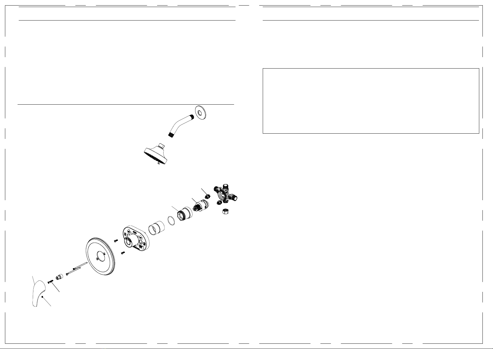
Many of these parts come preassembled. This
exploded diagram is to assist in trouble shooting.
Bonnet
Cartridge
Stop Valve
Handle
Screw
Screw
This manual suits for next models
3
Other DesignHouse Plumbing Product manuals


Popular Plumbing Product manuals by other brands


Kalia
Kalia Preciso BF1802 installation instructions

Homewerks
Homewerks 16-U42WNCHB Assembly instructions

Elkay
Elkay Lustertone ELU2118 Specifications

American Standard
American Standard Williamsburg Kitchen Faucets 4751 Series installation instructions

Toto
Toto MONO TX119LMBR quick start guide

Harvia
Harvia VARIANT Assembly instructions