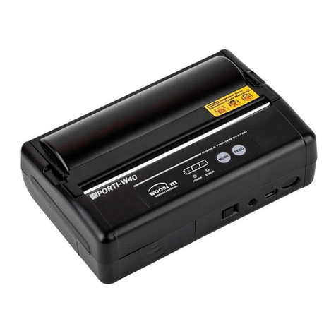
Detecto Cardinal P50 User manual

P50
Thermal Printer
Owner’s Manual
CARDINAL SCALE MFG. CO.
8525-M328-O1 Rev A PO BOX 151 xWEBB CITY, MO 64870
05/12 PH
(
417
)
673-4631 xFAX
(
417
)
673-5001
www.detectoscale.com

TABLE OF CONTENTS
INTRODUCTION . . . . . . . . . . . . . . . . . . . . . . . . . . . . Page 1
FEATURES . . . . . . . . . . . . . . . . . . . . . . . . . . . . . . . . Page 1
PRODUCT DESCRIPTION . . . . . . . . . . . . . . . . . . . . Page 2
ITEM INCLUDED IN THE PACKAGE . . . . . . . . . . . . Page 2
PREPARATION BEFORE USE . . . . . . . . . . . . . . . . . Page 3
Host Device Connection . . . . . . . . . . . . . . . . . . . . Page 3
Power Connection . . . . . . . . . . . . . . . . . . . . . . . . . Page 3
Wall Mounting . . . . . . . . . . . . . . . . . . . . . . . . . . . . Page 3
Paper Installation . . . . . . . . . . . . . . . . . . . . . . . . . . Page 4
PRECAUTIONS FOR THERMAL PRINT HEAD . . . . Page 6
CLEANING THE THERMAL PRINT HEAD . . . . . . . . Page 7
Procedures for Cleaning Thermal Print Head . . . . Page 7
OPERATION . . . . . . . . . . . . . . . . . . . . . . . . . . . . . . . Page 8
Troubleshooting . . . . . . . . . . . . . . . . . . . . . . . . . . . Page 8
CARE AND MAINTENANCE . . . . . . . . . . . . . . . . . . Page 9
FCC COMPLIANCE STATEMENT
WARNING! This equipment generates uses and can radiate radio frequency and if not
installed and used in accordance with the instruction manual, may cause interference to radio
communications. It has been tested and found to comply with the limits for a Class A
computing device pursuant to Subpart J of Part 15 of FCC rules, which are designed to
provide reasonable protection against such interference when operated in a commercial
environment. Operation of this equipment in a residential area may cause interference in
which case the user will be responsible to take whatever measures necessary to correct the
interference.
You may find the booklet "How to Identify and Resolve Radio TV Interference Problems" prepared by the Federal
Communications Commission helpful. It is available from the U.S. Government Printing Office, Washington, D.C.
20402. Request stock No. 001-000-00315-4.
All rights reserved. Reproduction or use, without expressed written permission, of editorial or
pictorial content, in any manner, is prohibited. No patent liability is assumed with respect to
the use of the information contained herein. While every precaution has been taken in the
preparation of this manual, the Seller assumes no responsibility for errors or omissions.
Neither is any liability assumed for damages resulting from use of the information contained
herein. All instructions and diagrams have been checked for accuracy and ease of
application; however, success and safety in working with tools depend to a great extent upon
the individual accuracy, skill and caution. For this reason the Seller is not able to guarantee
the result of any procedure contained herein. Nor can they assume responsibility for any
damage to property or injury to persons occasioned from the procedures. Persons engaging
the procedures do so entirely at their own risk.
8525-M328-O1 Rev A yP50 Owner’s
2

INTRODUCTION
The P50 Thermal Printer is designed and manufactured in a facility certified in ISO 9001
Quality, ISO 14001 Environment, OHSAS 18001 Health and Safety Management Systems
and ISO 13485 Medical Devices Quality Management.
NOTE: Please read this manual carefully and keep it handy for future reference.
FEATURES
1. Direct thermal printing
2. Compact design
3. Two-button operation
4. Thermal dot line printing
5. Number of dots/line: 384dots
6. Resolution: W 8dots/mm x H 16dots/mm
7. Max. printing speed: 40mm/sec
8. Max. paper roll diameter: 50mm
9. Printing width: 48mm
10.Wall mounting
11.Error and power indicators
12.Operating temperature: 20 to 50 °C.
13.Operating humidity: 0-50%
14.Power Supply: AC adaptor: 100-240VAC input, 12VDC (2A) output
15.RS-232 communication with scale (RS-232 cable included)
16.Product dimension: 110 x 110 x 107 mm
17.Box dimension: 175 x 157 x 158 mm (approx.)
18.Product weight: 0.275kg (approx.)
19.Total weight (product & box): 0.75kg (approx.)
8525-M328-O1 Rev A yP50 Owner’s 1

PRODUCT DESCRIPTION
FRONT VIEW
BACK VIEW
ITEMS INCLUDED IN THE PACKAGE
1. Printer unit
2. Wall mounting bracket for printer
3. Power adaptor
4. RS-232 connection cable
5. Plastic wall plugs
6. M3x25 screws
7. Metal bracket
8. M4x12 screws
9. Lock Washers
10.Instruction manual
Power Indicator
Error Indicator
Rear Bar
Paper Feed Button
Paper Roll Holder
Paper roll
Platen Roller
Platen gear
Groove
Detector
Metal Bracket
Screw Hole
ON/OFF Button
DC Jack
Wall Mounting Bracket
RS232 Port
8525-M328-O1 Rev A yP50 Owner’s
2

PREPARATION BEFORE USE
Host Device Connection
Connect the printer to the host device using the supplied RS232 cable.
Power Connection
Insert power adaptor plug into receptacle at rear of printer.
Wall Mounting
A. Drill two appropriate screw holes in the wall, and insert a plastic wall plug in each of the
two holes. Refer to (Fig.1).
(Fig.1)
B. Fasten the bracket securely to the wall with a screw in each of the two holes. Refer
to (Fig.2).
(Fig.2)
C. Slide the slot at the bottom of printer to bracket.
Metal Bracket
Align the metal bracket with the holes near the display in the back of the column and install
two (2) M4x12 screws with lock washers to secure the bracket to the column.
Refer to (Fig.3).
(Fig.3)
8525-M328-O1 Rev A yP50 Owner’s 3

Paper Installation
PRECAUTIONS FOR INSTALLING PAPER
zDo not touch the thermal print head and the detector directly when handling the
printer or replacing paper. Touching the print head may cause damage to the print
head and/or cause faulty printing.
zInstall the paper with the platen unit released. The printer will not auto load.
zBe sure paper is aligned straight in printer. Leave minimum 2 cm of the paper past
the cut-bar.
zWhen setting the platen unit, the reduction gear may interfere with the platen gear
and may cause the platen unit not to engage properly. In such a case, release the
platen unit and set it again.
zIf the paper is skewed, feed the paper until the paper straightens or open the printer
and re-install the paper roll.
zRemove jammed paper with the platen unit released. Do not pull the paper by force
– severe damage may occur.
A. Open the transparent cover.
B. Use the paper included in the package. Insert the paper spindle into the paper roll
and feed it in the groove. Refer to (Fig. 4).
Platen unit
Platen gear
Platen roll
Spindle
Groove
Detector
(Fig. 4)
8525-M328-O1 Rev A yP50 Owner’s
4

C. Set the paper straight to the printer and leave at least 2 cm of the paper out from the
cut-bar. Refer to (Fig.5). If the paper is skewed, feed the paper until the paper
becomes straight or install the paper again.
Cut -Bar
(Fig.5)
D. Turn the paper roll to tighten the paper and close the cover. Refer to (Fig.6).
Be sure the thermal
side of the paper f
down when installin
the paper into the
printer.
aces
g
Refer to (Fig.6)
(Fig.6)
8525-M328-O1 Rev A yP50 Owner’s 5

PRECAUTIONS FOR THERMAL PRINT HEAD
PRECAUTIONS FOR MAINTAINING PRINT QUALITY
AND LIFE OF THE THERMAL PRINT HEAD
zUsing anything other than the specified paper may reduce print quality and life of the
thermal print head. The followings are examples of incorrect paper:
- Poor printing quality due to low thermal sensitivity
- Abrasion of the thermal print head due to paper surface roughness
- Paper jams and unusual noise due to the thermal layer of the thermal paper sticking
to the thermal print head
- Printing fade due to low preservability of the thermal paper
- Electrolytic corrosion of the thermal print head due to inferior paper
zDo not open the paper packaging until ready to use.
zDo not use a paper roll with glued end or folded end. In case of using such roll papers,
replace with a new one before the end of the paper roll to prevent damage to thermal
print head.
zDo not print without paper; otherwise, the thermal print head may be damage.
zDo not hit or scratch the surface of the thermal print head with any sharp or hard
object. This could damage the thermal print head.
zDo not release the platen unit during printing; otherwise this may reduce the efficiency
of the printer and may cause damage.
zIf the platen is exposed to dirt, use a cotton swab soaked in alcohol to clean the platen.
8525-M328-O1 Rev A yP50 Owner’s
6

CLEANING THE THERMAL PRINT HEAD
PRECAUTIONS FOR CLEANING THE THERMAL PRINT HEAD
zDo not clean the thermal print head immediately after printing. Allow the thermal print
head to cool before cleaning.
zClean the thermal head with printer cover open.
zDo not use sandpaper, box cutter or knife etc. for cleaning. These items will damage
the heat element.
zIf the surface of the thermal print head is exposed to dirt, clean the thermal print head
to avoid poor print quality and damage to print head.
Procedures for Cleaning the Thermal Print Head
zTurn off the power before cleaning.
zOpen the printer cover.
zClean the thermal print head heat element and printer detector using a cotton swab
soaked in ethyl or isopropyl alcohol.
zClose the cover after the alcohol has dried completely.
Detector
Thermal head heat element
(Fig.7)
8525-M328-O1 Rev A yP50 Owner’s 7

OPERATION
1. Connect power adaptor to printer, and turn printer on using the [ON/OFF] button located
at the rear of printer. The Power Indicator will light green.
2. In print mode of the scale, the report will be printed.
3. Press [ON/OFF] button to turn off printer.
TROUBLESHOOTING
1. Why is the printing quality deteriorated?
zIf the printer has not been used for a prolonged period of time, the platen could be
deformed and may cause print quality to deteriorate. In this case, feed paper for a
while to recover deformation of the platen.
2. Why can’t I feed in the paper?
zThe platen and the thermal head may be stuck together and cause paper feed
difficulty. You may need to release the platen unit and set it back again.
3. Paper Jam
zDo not pull the paper and change angle of the paper coming out while printing.
zIf the printer main body and the platen unit are not placed in proper position, the
paper jam may occur. If the platen is exposed to dirt, the paper jam may occur.
zRemove jammed paper with the platen unit released. Do not pull the paper by force
– severe damage may occur.
4. Why can’t I print the results in the paper?
zCheck whether the paper is installed properly. Only the thermal side (shiny side)
can be printed. Be sure the thermal side of the paper faces down when installing
the paper into the printer. Refer to (Fig.5).
5. Printing stuck or stopped
zCheck whether the thermal print head or platen is dirty and clean it. Refer to
Cleaning the Thermal Print Head.
8525-M328-O1 Rev A yP50 Owner’s
8

CARE AND MAINTENANCE
zAvoid excessive impact or vibration to the printer.
zUnplug the power supply before cleaning the printer.
zClean the outside of the printer with a soft dampened cloth. Do not use solvents or
immerse the unit in water.
zDo not disassemble the printer; it contains no user serviceable parts. Damage to the
printer may occur as a result of improper handling.
zDo not open the print paper packaging until ready to use.
zClean the thermal print head and printer sensor using a cotton swab soaked in ethyl
or isopropyl alcohol.
zDo not touch the thermal print head directly when handling the printer.
zDo not touch the platen and prevent any objects from getting caught in paper winder.
zDo not apply stress to the platen unit while printing.
zThe printer is not water resistant. Prevent contact with water and do not operate with
wet hands as it may damage the printer or cause personal injury.
zThe printer is not dust proof. Never use the printer in a dusty place, as it may
damage the thermal print head and paper drive system.
zDo not use the printer in corrosive environment as it may cause contact failure.
8525-M328-O1 Rev A yP50 Owner’s 9

8525-M328-O1 Rev A yP50 Owner’s
10
Table of contents
Other Detecto Printer manuals
