Leica IP S User manual

Leica IP S
Automated
printing system
for microscope slides
Operating Instructions
Leica IP S
V1.6 English - 07/2005
Always keep this manual together with the instrument.
Read this instruction manual carefully before working
with the instrument.


3
Leica IP S
The information, numerical data, notes and value
judgments contained in this manual represent the
current state of scientific knowledge and state-
of-the-art technology as we understand it follow-
ing thorough investigation in this field.
We are under no obligation to update the present
manual according to the latest technical devel-
opments, nor to provide our customers with addi-
tional copies, updates etc. of this manual.
For erroneous statements, drawings, technical il-
lustrations etc. contained in this manual we ex-
clude liability as far as permissible according to
the national legal system applicable in each indi-
vidual case. In particular, no liability whatsoever
is accepted for any financial loss or consequen-
tial damage caused by or related to compliance
with statements or other information in this man-
ual.
Statements, drawings, illustrations and other in-
formation as regards contents or technical de-
tails of the present manual are not to be consid-
ered as warranted characteristics of our
products.
These are determined only by the contract provi-
sions agreed between ourselves and our custo-
mers.
Leica reserves the right to change technical spe-
cifications as well as manufacturing processes
without prior notice. Only in this way is it possible
to continuously improve the technology and man-
ufacturing techniques used in our products.
This document is protected under copyright laws.
Any copyrights of this document are retained by
Leica Microsystems Nussloch GmbH.
Any reproduction of text and illustrations (or of
any parts thereof) by means of print, photocopy,
microfiche, web cam or other methods – includ-
ing any electronic systems and media – requires
express prior permission in writing by Leica Mi-
crosystems Nussloch GmbH.
For the instrument serial number and year of ma-
nufacture, please refer to the name plate at the
back of the instrument.
© Leica Microsystems Nussloch GmbH
NOTE
Published by:
Leica Microsystems Nussloch GmbH
Heidelberger Str. 17 - 19
D-69226 Nussloch
Germany
Phone: +49 (0)6224 143-0
Fax: +49 (0)6224 143-200
e-Mail: [email protected]
Internet: http://www.histo-solutions.com

4Instruction manual V 1.6 – 07/2005
Table of contents
1. Important Notes................................................................................................................................................ 5
2. Safety ................................................................................................................................................................. 6
2.1 Safety instructions .......................................................................................................................................................................... 6
2.2 Warnings........................................................................................................................................................................................... 6
3. Instrument components and specification ................................................................................................. 8
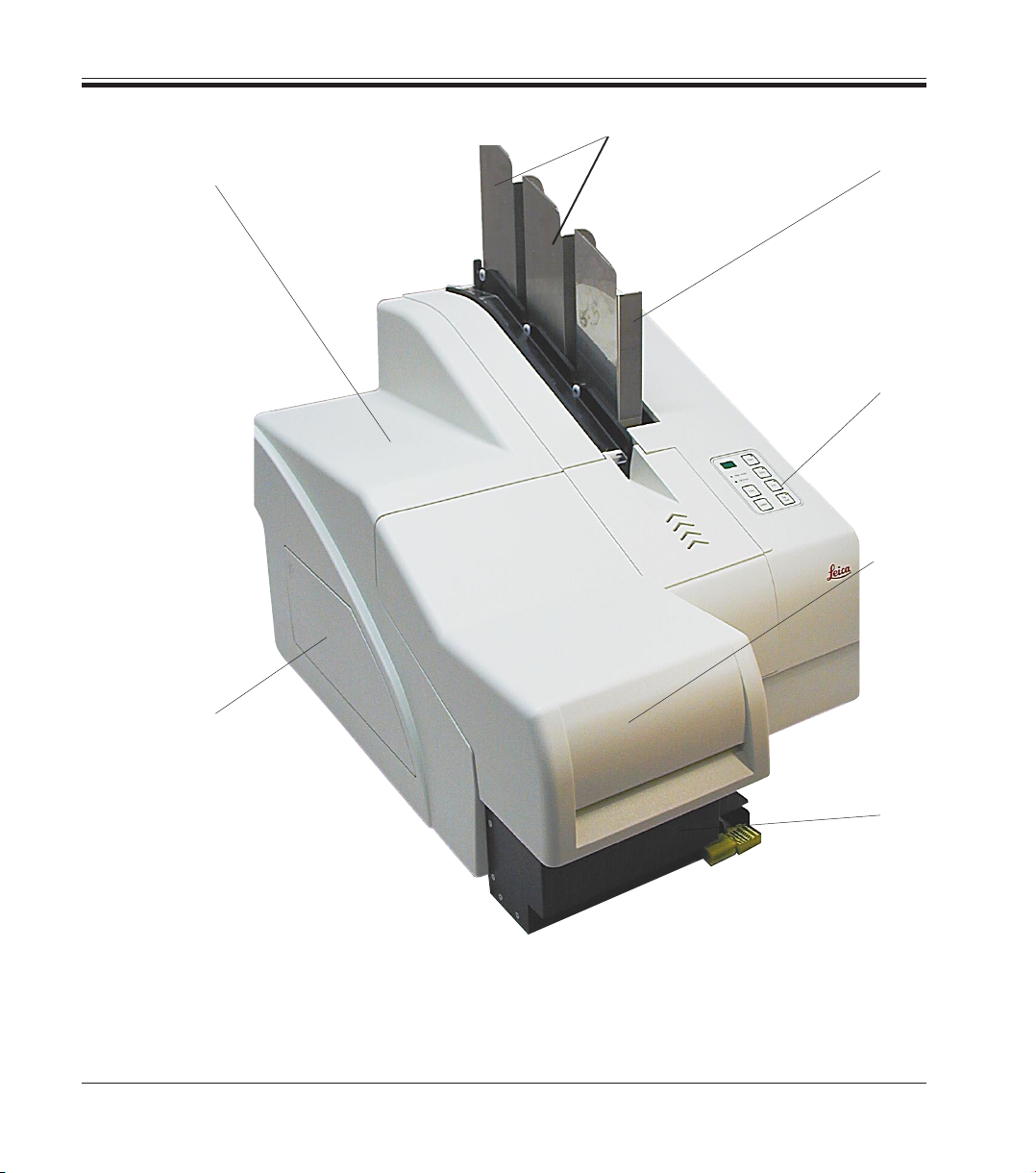
3.1 Overview - instrument .................................................................................................................................................................... 8
3.2 Technical data ............................................................................................................................................................................... 10
3.3 Print specifications ....................................................................................................................................................................... 12
3.3.1 Requirements for microscope slides ......................................................................................................................................... 12
3.3.2 Print specifications ....................................................................................................................................................................... 14
3.3.3 Printing bar code ........................................................................................................................................................................... 15
3.3.4 Resistance against reagents ....................................................................................................................................................... 17
4. Setup ................................................................................................................................................................ 18
4.1 Site requirements .......................................................................................................................................................................... 18
4.2 Installing the printer ...................................................................................................................................................................... 18
4.3 Standard delivery - packing list .................................................................................................................................................. 19
4.4 Installing the manual unload system .......................................................................................................................................... 20
4.5 Automated unload station (optional) .......................................................................................................................................... 21
4.6 Installing/exchanging the flashtube ........................................................................................................................................... 22
4.7 Filling and inserting the magazines ............................................................................................................................................ 24
4.8 Electrical connection .................................................................................................................................................................... 25
4.9 Exchanging the cartridge ............................................................................................................................................................. 26
4.10 Installing the printer driver .......................................................................................................................................................... 29
5. Operation ......................................................................................................................................................... 32
5.1 Control panel functions ................................................................................................................................................................ 32
5.2 Display indications ........................................................................................................................................................................ 37
5.3 Alarm functions.............................................................................................................................................................................. 39
5.4 Printer driver settings ................................................................................................................................................................... 40
6. Cleaning and maintenance .......................................................................................................................... 43
6.1 Cleaning the instrument ............................................................................................................................................................... 43
6.2 Print head cleaning ....................................................................................................................................................................... 46
6.3 General maintenance ................................................................................................................................................................... 47
7. Troubleshooting ............................................................................................................................................. 48
7.1 General ............................................................................................................................................................................................ 48
7.2 Status messages ........................................................................................................................................................................... 49
7.3 Error messages .............................................................................................................................................................................. 50
7.3 Changing the flash bulb ................................................................................................................................................................ 53
7.4 Power failure .................................................................................................................................................................................. 53
7.5 Replacing the secondary fuses ................................................................................................................................................... 54
8. Warranty and service.................................................................................................................................... 55

5
Leica IP S
1. Important Notes
Symbols used in this manual
Warnings appear in a grey box and
are marked by a warning triangle
.
Notes, i.e. important user informa-
tion appears in a grey box and is
marked by an information symbol
.
Figures in brackets refer to item
numbers in drawings.
Function keys to be pressed on the
touch screen are written in bold-
print capital letters.
(5)
ENTER
and their meaning Designated use
Leica IP S slide printer for printing microscope
slides.
• The instrument has been designed for use in
pathology, histology, cytology, toxicology and
similar laboratories, and there only for print-
ing microscope slides.
• Imprints of adequate quality and resistance to
subsequent processing in tissue processors
can only be guaranteed when using the slides
and reagents specified in Chapter 3.3.
• The instruments may be operated only accord-
ingtotheinstructionscontainedinthismanual.
Any other use of the instrument
is considered improper!
Prior to shipment, every instrument
undergoes a final quality inspection.
Therefore, some traces of use such
as scratches and marrs, caused by
microscope slides that have sharp
edges, might be visible.
Fig. 1
Instrument type
All information provided in this manual applies
only to the instrument type indicated on the title
page. A name plate indi-
cating the instru-
ment serial num-
ber is attached to
the back of the in-
strument.
Qualification of personnel
• The Leica IP S may be operated only by
trained laboratory personnel.
• All laboratory personnel designated to oper-
ate the Leica IP S must read this instruction
manual carefully and must be familiar with all
technical features of the instrument before
attempting to operate the Leica IP S.

6Instruction manual V 1.6 – 07/2005
Make sure to comply with the safety instructions and warnings in this chapter.
Make sure to read these instructions, even if you are already familiar with the operation
and use of other products.
2. Safety
2.1 Safety instructions
This instruction manual includes important instruc-
tions and information related to the operating safety
and maintenance of the instrument.
It is an important part of the product, which must
be read carefully prior to operating the instru-
ment for the first time and must always be kept
with the instrument.
If additional requirements on acci-
dent prevention and environmental
protection exceeding the scope of
this manual, are imposed by laws/
regulations of the country of opera-
tion, this instruction manual must be
supplemented by appropriate instruc-
tions to ensure compliance with such
requirements.
This instrument has been built and tested in ac-
cordance with the following safety regulations on
information technology devices:
• EN 55022
• EN 55024
• EN 61000-3-2
• EN 61000-3-3
• EN 60950
• EN 60491
• EN 60598-2-9
In order to maintain this condition and to ensure
safe operation the operator must comply with the
instructions and warning contained in this in-
struction manual.
The protective devices on both instrument and accessories may neither be removed nor
modified.
Only authorized and qualified service personnel may access and repair the internal com-
ponents of the instrument.
2.2 Warnings
The safety devices installed in this instrument by the manufacturer only constitute the basis for
accident prevention.
Primarily responsible for accident-free operation is above all the institution which owns the in-
strument and, in addition, the designated personnel who operates, services or repairs the instru-
ment.
To ensure trouble-free operation of the instrument, make sure to comply with the following in-
structions and warnings.

7
Leica IP S
2. Safety
Warnings - Transport and Installation
• Once unpacked, the instrument may be transported only in an upright position.
• Do not expose the instrument to direct light (windows)!
• The instrument MUST be connected to an earthed mains power outlet socket.
The instrument must not be connected to an extension cord without protective earth
conductor.
• Do not operate the instrument in rooms with explosion hazard.
• Condensation water may form in the instrument, if there is an extreme difference in
temperature between the warehouse and the installation site and if air humidity is high
at the same time. In these cases, a waiting period of at least two hours must be ob-
served before the instrument is switched on. Failure to adhere to this waiting period
may result in damage to the instrument.
Warnings - Markings on the instrument itself
• Warning labels on the instrument marked with a warning triangle indicate that the cor-
rect operating instructions (as defined in this manual) must be followed when operat-
ing or replacing the item marked.
• Failure to adhere to these instructions may lead to accidents causing personal injury
and/or damage to the instrument or accessories.
Warnings - Instrument operation
• The Leica IP S may be operated by trained laboratory personnel only, according to its
designated use and as per the present instruction manual.
• In the event of an emergency, switch off the mains switch and unplug the instrument
from mains.
• Do not touch the ramp during operation. Risk of injury, caused by microscope slides
that have sharp edges or by broken glass.
• Do not open the reflector flap of the flashlight while the instrument is ON - risk of burns
and blinding.
Warnings - Cleaning and maintenance
• Each time before cleaning, switch the instrument OFF and unplug from mains.
• Do not use alcohol, detergents containing alcohol (window cleaner!), abrasive clean-
ing powders and/or solvents containing acetone or xylene for cleaning. The painted
surfaces and the control panel of the instrument are not resistent to xylene or acetone!
• Prevent liquids from entering the interior of the instrument while the instrument is be-
ing cleaned or during operation.

8Instruction manual V 1.6 – 07/2005
3.1 Overview - instrument
3. Instrument components and specification
Fig. 2
Instrument components
1 - Basic instrument
2 - Slide Magazines
2.1- Magazine no. 1
3 - Control panel
4 - Lid
5 - Cover - cartridge receptacle
6 - Unload station (manual)
2
3
5
1
4
6
2.1

9
Leica IP S
3. Instrument components and specification
Fig. 4
Rear panel and electrical connections
Fig. 3
Front view without lid
2.1-2.3- Magazine receptacles nos. 1 - 3
7 - Drying module
8 - Cover - flashtube
9 - Slide carrier
10 - Print head
11 - Magazine holder
12 - Feeding chute with cover
13 - Transfer point : chute - slide carrier
14 - Location plate
15 - External alarm jack
16 - Socket for printer cable
17 - DIL - Switch
18 - Mains connection
19 - Mains switch
20 - Storage fluid cartridge
21 - Secondary fuses
22 - Drawer for broken glass
Attention item nos. 20
This is the delivery state!
Prior to operation, the cleaning fluid
cartridge must be exchanged for an
ink cartridge - see chapter 4.9!
21 19 18 20 22
16
15
17
9
12
7810
13
2.1 -2.3
11
3
2
1
14

10 Instruction manual V 1.6 – 07/2005
3. Instrument components and specification
3.2 Technical data
General
Admissions: all instrument-specific admission labels are located at
the rear panel of the instrument, next to the name plate
Nominal voltage: 100 V - 240 V
230 V - 240 V
Nominal frequency: 50 to 60 Hz
Maximum power draw at 100 - 120 V: 4.0 A
Maximum power draw at 200 - 240 V: 2.8 A
Leakage current at 240 V/ 50 Hz approx. 2.4 mA
Maximum power draw: 480 VA
IEC 1010 classifications: protective class 1
pollution degree 2
overvoltage installation category II:
• 800 V impulse (120 V systems)
• 1500 V impulse (240 V systems)
Secondary fuses: 2 x 3.15 A T (UL - listed)
Operating temperature range: 15 °C to 35 °C
Relative humidity: 10 % to 80 %, non-condensing
Dimensions and weight
Dimensions of basic instrument
Width x Depth: 475 x 650 mm
Height - with magazine inserted: 560 mm
Dimensions with unload station connected
Width x Depth: 548 x 650mm
Height - with magazine inserted: 655 mm
Weight
Basic instrument:- dry weight: approx. 28 kg
Weight incl. packing material: approx. 65 kg
Unload station - dry weight: approx. 14 kg
Weight incl. packing material: approx. 32 kg

11
Leica IP S
Performance
Loading capacity: up to 3 magazines,
up to 150 slides per magazine
Printing speed 1
Batch job printing: 14 slides/minute (two-line printing)
Single-slide printing: 10 secs per slide
Ink cartridge capacity 2:approx. 60.000 or 3.5 month
Lifespan of flashtube: approx. 150,000 flashes
Printing
Print resolution:3 360 x 360 dpi / 180 x 180 dpi, selectable
Imprintable objects: glass microscope slides with coated edge
76 x 26 mm, max. 1,2 mm high
Print formats: slide
Imprint surface: max. 25,4 x 18,0 mm
PC system requirements
IBM-compatible PC
Processor frequency: minimum 800 Mhz
Main memory (RAM): minimum 256 MB
Hard drive: minimum 6 GB
CD ROM drive
1 free serial port
Operating system: Windows NT, Windows 2000, Windows XP
1) Average value - exact speed in each individual case depending on system configuration and
software used.
2) Average value - exact number of slides in each individual case depending on quantity being im-
printed and on density of imprint.
3) Measured in addressable dots per inch
3. Instrument components and specification

12 Instruction manual V 1.6 – 07/2005
3.3.1 Requirements for microscope slides
• To reduce the amount of glass dust and the
risk of mechanical failures, use only clipped
corner slides (45° angle on each corner).
• Slides to be used in the printers must be stored
appropriately in closed containers and pro-
tected from dust and moisture.
• Positively charged slides are inherently sticky
so they require special handling to insure reli-
able mechanical handling by the instrument.
• When the print job is complete, the printed
surface of the slide may be handled immedi-
ately. Please be aware, however, that the spe-
cial ink is alcohol based and exposure to al-
cohol in combination with physical contact
(rubbing) could cause the print quality to de-
grade.
Fig. 5
3.3 Print specifications
Only standard microscope slides with imprintable
colored edges (23) can be imprinted in the Leica
IP S (see Fig. 5).
Printing directly onto the glass is not possible.
The following slide sizes can be imprinted in the
Leica IP S: 76 x 26 mm, max. 1.2 mm thickness.
3. Instrument components and specification
23
The texture of the slide print surface is extremely
important for optimal print quality and durability.
The print surface varies considerably between
manufacturers, color selection and coated (pos-
itively charged) versus uncoated surfaces.
They can even vary from slide to slide in the
same lot.
Coloured print surfaces, other than pure white,
contain pigments that help the ink spread evenly
and adhere strongly.
White print surfaces should always be tested for
print quality and ink adherence before purchase.
Some slides have been coated over the print sur-
face as well as the glass, which can create prob-
lems with the adherence of the ink.
These slides should also be tested for print qual-
ity and ink adherence before purchase.

13
Leica IP S
Caution!
Slides made by other manufacturers must be tested before use. The test must include the
following steps:
Mechanical compatibility with the instrument. Imprint quality.
Chemical and mechanical resistance of the imprints against the reagents the slides will
be exposed to during the subsequent processing steps.
Important!
Leica Microsystems assumes no responsibility whatsoever for any damages due to im-
prints of poor quality or imprints made with non-reagent-resistant ink.
Slides manufactured by the same companies, but with special coatings as e.g. Superfrost
®-Plus slides for immunohistochemical applications proved to be difficult with regard to
processability, print quality and ink resistance.
We recommend these slides only for alphanumeric imprints (no for bar code) and also
recommend to test these slides prior to using them to verify whether the imprints on such
slides are sufficiently resistant to reagents.
The following slides have been successfully tested with the Leica IP S:
Clipped corner slides
• Erie – Leica Ink Jet Slides*, Superfrost (plain and plus)
• Knittel GmbH – Starfrost bevelled edge 45°
• Matsunami – Clipped corner slides
• Menzel – Superfrost
• Okando – Premier coloured end, plain and charged, bevelled edge
* Highly recommended, especially for printing 1 and 2 dimensional bar codes.
Distributed by many major lab supply companies.
Tested and recommended print media for the Leica IP S ink jet printer
IMPORTANT!
The use of other print media may result in unsatisfactory print quality and/or jamming of
slides/cassettes during the printing process!
If the slides/cassettes you are currently using are not listed above, please contact your
local Leica Microsystems’ representative.
3. Instrument components and specification

14 Instruction manual V 1.6 – 07/2005
3.3.2 Print specifications
Width Height
Format Dots mm Dots mm
Slide 360 25.4 256 18.0
Print resolution
The print head of the instrument has a fixed reso-
lution of 360 dpi in both directions (vertical and
horizontal).
Each printed line has a maximum height of 128
dots, corresponding to 9.03 mm.
Therefore, a maximum of 2 lines can be printed
on the slides.
In horizontal direction, the printable surface is
limited only by the size of the object to be imprint-
ed (Fig. 6).
The above values must be taken into consider-
ation when defining the print area (“paper size“)
in the application you are going to print from.
Print resolution
The printing area parameters listed in the table
below are defined in the printer driver.
24
Fig. 6
Print quality Quality and resolution of the imprints depend on:
• the material of the imprintable surface / the dyes used to color the
imprintable surface.
• the structure of the imprintable surface (24).
The final resolution of the imprints is not only determined by the resolution of
the print head.
If the slide surface is not capable of 360 dpi resolution, “running“ ink will
lead to poor printing results. In such cases it is better to work at a lower
resolution.
The printer driver therefore allows you to change the resolution from 360 dpi
to 180 dpi (see chapter 5.4 for further details).
3. Instrument components and specification

15
Leica IP S
3. Instrument components and specification
3.3.3 Printing bar code
Printing readable bar code depends on various factors that need to be taken
into consideration in order to achieve results suitable for reliable and du-
rable archiving.
The main factors influencing the bar code results are:
• printer technology
• how the bar code is created
• the type of object being printed on
• the type of scanner used to read the bar code
Printer technology
• As a dot matrix printer, the IP C can handle information only in the form
of dots printed or not printed. It is not possible to transmit bar code data
or to select specific bar code types or use the printer to create and print
the bar code required.
Creating bar codes
• Since there is only limited printing space on the slides, the bar code
should not contain more information than necessary.
• You should use an error-checking code, which makes it easier for the
bar codes scanners to recognize possible errors. Some codes even sup-
port error correction.
• When calculating and creating bar code, always bear in mind the resolu-
tion of the printer.
The module size is the width of the smallest element of a bar code. Wider
bars and spaces are calculated in multiples of the module size.
The module size always has to be an entire divisor of the printer resolu-
tion, as, due to the technology applied, only ‘whole’ dots can be printed.
Reading errors may occur (even if the print appears to be crisp and cor-
rect), if, due to conversion, module width and resolution do not match
any longer.
Data should never be printed as bar code only, but also as text
(line of optical characters above or below the bar code), to en-
sure that no information is lost for the above reasons.

16 Instruction manual V 1.6 – 07/2005
3. Instrument components and specification
Bar code scanners
The scanning results obtained not only depend on the correct bar code cre-
ation and on the quality of the cassettes but also on the features of the
barcode scanner used.
Features to bear in mind are:
• Reading tolerance:
difference between actual bar width and nominal module size.
• Light color:
the light color of the barcode scanner should be opposite (highly
contrasting) to the color of the cassettes being used.
• Optical resolution:
must be better than the module size.
Depending on the application, the following features should also be consid-
ered:
• Maximum readable distance
• Maximum inclination angle
Leica has tested successfully the following readers:
Datalogic - Model ‘Gryphon’ (for 1D-Barcode)
Datalogic - Model ‘Lynx D 200’ (for 1D and 2D-Barcode)
Requirements for Barcode Printing
The quality and readability of printed barcodes will depend on several fac-
tors that include:
• Texture and quality of the print surface on the selected cassette or slide
• Color of the selected cassette or slide
• Bar code style
• Number and types of characters required in the barcode
• The quality and resolution capabilities of the bar code reader
As always, using Leica recommended print media would produce the high-
est quality print. However, it is highly recommended that any barcode solu-
tion be tested prior to implementation.
Please check with your local representative for details on achieving the
maximum number of characters with 1D or 2D bar codes.

17
Leica IP S
3. Instrument components and specification
3.3.4 Resistance against reagents
Important!
All laboratories must perform their own tests to ensure that the ink is resistant against the
various reagents the slides will subsequently be exposed to.
A wide range of factors beyond Leica’s control can have negative effects on the results.
The test conditions stated below can therefore only serve as an outline for individual
laboratory test specifications.
The laboratory operating the unit shall bear full responsibility for the legibility of the im-
print after processing with reagents.
Test conditions
Imprinted slides were tested with a variety of reagents in an environment
simulating the conditions present during tissue processing.
The following slide types were tested:
• Erie – Leica Ink Jet Slides*, Superfrost (plain and plus)
• Knittel GmbH – Starfrost bevelled edge 45°
• Matsunami – Clipped corner slides
• Menzel – Superfrost
• Okando – Premier coloured end, plain and charged, bevelled edge
A variety of colors of all of the above slide types (although not all colors
available of each slide type) were tested.
An influence of the slide color on the resistance of the imprint could not be
verified.
It cannot be guaranteed that the ink will be absolutely smudge-proof under all foresee-
able laboratory conditions, as stability of the ink against wiping largely depends on the
surface structure of the imprint field of the slide being imprinted.
Important!
The imprint field of imprinted slides should never be touched or wiped while damp.

18 Instruction manual V 1.6 – 07/2005
4. Setup
4.1 Site requirements
The installation site must be well-ventilated.
The instrument must not be operated in areas at risk of explosion.
When unpacking the printer, at least
two people (one person on each
side of the printer) are required to
lift the printer out of the box and
place it onto the laboratory bench.
• Check the instrument for transport damage.
• Check all accessories delivered against your
order to make sure there are no discrepancies.
• Remove the transport safety device (25, Fig. 7)
from the instrument.
• Carry out the following installation steps:
• Insert the shielding glass
• Insert the flashtube (see page 22).
• Connect to mains.
• Remove storage fluid cartridge with ink
cartridge.
• Establish data connection to PC.
• Install printer driver.
• Fill with cassettes.
• Run a test print (see page 27).
Fig. 7
Carefully pull out the blue transport safeguard
(25) that protects the print head during transport.
Carefully remove any adhesive tape remnants.
25
4.2 Installing the printer
• The Leica IP C needs approx. 650 x 500 mm
floor space. The printer needs approximately
20 cm (8”) of free space around all sides of
the instrument.
Additional space is required for the PC con-
taining the control software.
• Stable laboratory bench and practically vibra-
tion-free floor.
• Stable ambient temperature between +10 °C
and +35 °C.
• Relative air humidity of maximum 80 %, non-
condensing.
• Avoid vibrations, bright direct light and strong
temperature fluctuations.
• The AC socket must be close to the printer and
easily accessible.

19
Leica IP S
4. Setup
4.3 Standard delivery - packing list
The Leica IP S standard delivery consists of the following items:
1 Leica IP S, basic instrument without unload station 0601 33201
1 Storage fluid cartridge (in the instrument) 0601 35811
1 UV-Ink cartridge Leica 0601 42350
1 Entnahmestation (manuell), kpl. 0601 35990
1 Accessory-Kit consisting off: 0601 38350
1 Flash tube 0601 37152
3 Magazines for slides, (1 pack of 3) 0601 36689
1 Set of power cords:
1 Power cord "UK" ST/BU F-5A 0411 36959
1 Power cord "D" 0411 36958
1 Power cord "USA-C-J" 0411 36960
1 Printer cable, serial 0601 37044
1 Tool set:
1 Screw driverr 3 x 50 0170 11568
1 Allen key size 2.5 0222 04137
1 Brush “Leica“ 0183 30751
1 Set of replacement fuses:
2 Fuses 3.15 A T 6943 03150
1 Protecting block (in the instrument) 0601 39615
2 shielding glass 0601 42533
1 Cleaning swabs, pack of 25 0601 39637
1 IP CD ROM (printer driver and documentation,instruction manual) 0601 37173
Optionales Zubehör:
• Automated multi-level cassette unload station (for Leica IP S) 0601 33225
• Set of slide trays for unload station S (pack of 10). 0601 33252
• Magazine holder ”S” for 6 magazines 0601 36940
• Magazine loading help 0601 36979

20 Instruction manual V 1.6 – 07/2005
4. Setup
4.4 Installing the manual unload system The unload system supplied consists of:
26 - Unload station
27 - Shielding cover
28 - Collar screws (3 pcs.)
29 - Slotted screws with washers (2 pcs.)
Install as follows (see Fig. 8):
• Open lid (4).
• There are 5 tapped holes (2 x item no. 30 and
3 x item no. 31) in the installation surface lo-
cated below the reflector.
• With a screwdriver, insert 3 collar screws (28)
in tapped holes (31) as far as they will go.
• Then, fasten cover (27) in tapped holes (30) us-
ing the two slotted screws (and washers) (29).
• To fasten the unload station to the instrument,
place the wider end of the three oblong holes
(32) over the heads of the three collar screws
(28). Press the unload station against the in-
stallation surface, and simultaneously push it
to the right until it locks in place (see enlarged
detail).
If the unload station does not easily slide past
the shielding cover, slightly lift the front end of
the instrument.
• Close lid (4) making sure the unload station
does not obstruct the lid.
When working with the manual un-
load station the slides imprinted
must be removed in regular inter-
vals. Otherwise they will start piling
up in the unload station, printing
will stop and error code “44“ will
be displayed.
Fig. 8
27
26
28
29
32
The enlarged detail shows
the correct location of the
collar screw once the un-
load station has been locked
in place correctly.
30
31
31
4
28
Other manuals for IP S
2
Table of contents
Other Leica Printer manuals