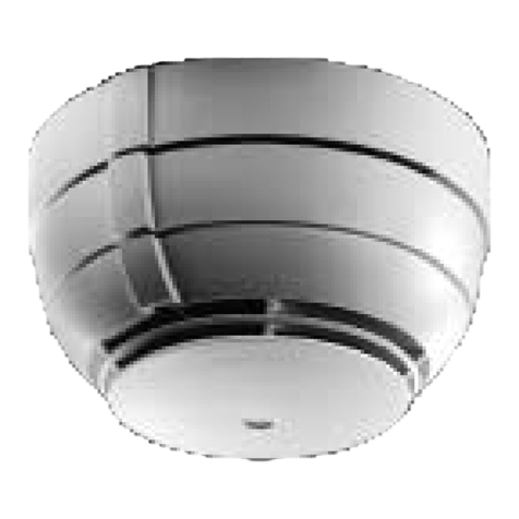
Detector Inspector DI240I User manual

1
Model number: DI240I
Detector Inspector Smoke Alarm User Manual
Model number: DI240I Date: 2020.07.07 REV A
Read All Instructions BeforeInstallation
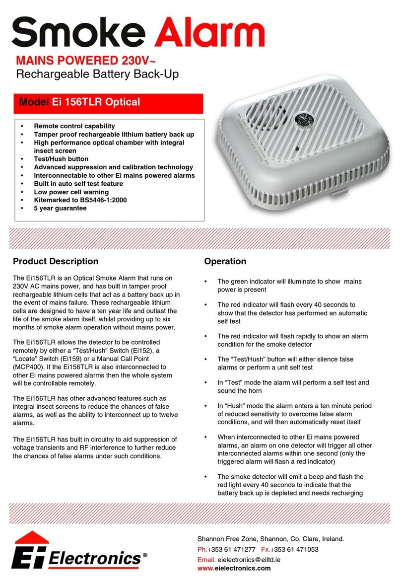
Thank you for buying our smoke alarm. This manual will show you
how to install and operate it.
Please keep this manual in a safe place for future use.
AS3786:2014
DI240I Specifications:
Main Power Source
220-240 V AC/50 Hz
Secondary Power Source
DC 3V battery: Pairdeer CR17450
AC Operating Current
100mA
Interconnecting
Max. 24 alarms (wired 150m maximum) Compatible RF Module DI240WI (not included)
Operating Temperature
0 °C to 40 °C
Ambient Humidity
≤ 93%
Alarm Sensitivity
0.111-0.182dB/m
Alarm Volume
≥ 85dB(A) @ 3m
Sound Pattern
ISO8201(BI 0.5s - pause 0.5s - BI 0.5s - pause 0.5s - BI 0.5s - pause 1.5s, with the
RED LED flashing, repeat this alarm pattern)
Comply with
AS3786:2014
WARNING
•
Only an appropriately qualifiedelectrician can install this alarm.
•
Only use this alarm for the purpose described in these instructions and ensure the installation meets with the correct
wiring rules and regulations.
•
This alarm’s wire leads may present a voltage hazard.
•
Always disconnect AC power before installing or removing.
•
Ensurethe producthas been correctly installed and testedfor safe operationbeforereconnecting to electricity.
•
Do not connect the interconnection wire tothe Live or Neutral terminal.
•
Non-pure sinusoidal power sources are not suitable for this smoke alarm (e.g. derived from square-wave invertors).
•
Avoid exposing this alarm to moisture.
Failure to follow these instructions may result in death or serious injury.
Product Function Description
Function
What the alarm is doing
What you need to know
Standby status
The Red LED flashes every
40 seconds.
The unit is working.
AC power indication
The Green LED continuously
illuminates.
The unit is receiving AC power.
Low battery warning
The unit chirps with Red LED
flashing every 40 seconds.
The battery is too low, replace battery as soon as possible.
Fault warning
The unit chirps between the
Red LED two times flashing.
The unit is faulty. Refer to “Trouble Shooting”.
End-of-life warning
The unit chirps between the
Red LED flashing twice.
After 10 years the unit sends out an end-of-life warning and
will need replacing.
Test function
The Red LED flashes every
second with alarm
sounding until you release
the TEST button.
Test by pressing the TEST button for least 5 secs.
The alarm will sound if all electronic circuitry, horn and
battery are working properly.
Refer to “Trouble Shooting” if the alarm doesn’t sound.
Silence function
The Red LED flashes every
8 seconds.
This smoke alarm has a built-in Silence feature.
If cooking or other non-hazardous sources trigger the alarm,
it can be silenced for 10 mins by pressing the HUSH button
for at least 2 seconds.
After 10 mins the alarm resumes normal operation.
Fire alarm
The Red LED flashes every
second, with alarm sounds.
The alarm sounds when it detects fire.
Interconnection alarm
The alarm sounds without Red
LED flashing.
The unit will enter the interconnection alarm mode when it
receives wire interconnection alarm signals or wireless alarm
signals.
Do Not Disturb
The Red LED flashes every
40 seconds.
The unit will stop audible warnings for approximately 10 hours
from low battery or fault mode when the HUSH button is
pressed.
Pluggable module
(Optional)
Refer to the pluggable module
user manual.
Optional pluggable wireless module.
WARNING
•Ifthe alarm sounds, and itisnotbeing tested,itmeansthe unitdetected smoke. THE SOUND OFTHE ALARM
REQUIRES YOUR IMMEDIATE ATTENTION AND ACTION.
•Before using the Silence function, identify the source of the smoke and make sure you are safe. After a 10 minute
silence, the unit will resume normal operation.
•Do not use an open flame to test your alarm.

2
Model number: DI240I
How to Install Pluggable RFModule to Interconnect (Optional)
Replace the Backup Battery
①Press the‘PUSH’button ② Open the alarm ③Open the battery cover
•
We recommend i
nstalling an alarm in every room with an electrical appliance (i.e. portable heaters orhumidifiers).
•
We recommend i
nstalling analarmin every bedroom.
•
When mounting an alarm on the ceiling, put it at least 300mm from the side wall (see Diagram1).
•
When mounting an alarm on the wall, put it no more than 500mm below the ceiling and at least 300mm from any
corner junction (See Diagram 1).
•
If your bedroom hallway or room is more than 10m long, put a smoke alarm at both ends.
•
For rooms with peaked or cathedral ceilings position alarm between 500mm and 1500mm from the highest point of
the ceiling. (See Diagram 1).
⑥ Finish
⑤Close the battery cover,close
the alarm
④ Replace battery
TRY AVOID THE FOLLOWING LOCATIONS
⚫
Battery type: Pairdeer CR17450
⚫
Turn off the AC power before replacing the battery.
⚫
Always test the alarm after putting in a new battery using the test facility.
Recommended Locations for Alarms
•
Observe & follow all local and national regulations and building codes.
•
We recommend i
nstalling an alarm in all stairways.
•
We recommend i
nstalling an alarm on every level.
Pluggable module
1. In the garage where there are combustible products such as fumes from your car.
2. Places where the temperature can fall below 0℃or go above 40℃.
3. Dusty areas.
4. Where humidity exceeds 93%.
5. Areas infested with insects.
6. Smoke alarms should not be installed within 900mm of:
•A kitchen
•A bathroom containing a bath or shower.
•Forced air supply ducts from heating or cooling systems.
•Ceiling orwhole house ventilating fans, or other high airflow areas.
7. Place the alarm away from fluorescent lights as the electronic “interference”they cause can trigger the alarm
unnecessarily.

3
Model number: DI240I
Diagram C
Screws
Diagram B
Installation Sketch
Wiring Instructions
TERMINAL:
I-Connect : Interconnection
N : Neutral
E-Loop : No wiring
A : Active
CAUTION
•All interconnected smoke alarms must be supplied from the same circuit.
•A common Neutral must be used for Interconnect to function.
•The maximum number of interconnected alarms youcan have is 24.
•The maximum wiring length between the first and last alarm is 150m.
•DO NOT connect the interconnect wires to Live or Neutral.
•Use a minimum of 1.5 mm2 250V insulated wire for all wiring, including interconnectingwiring.
How to Mount Your Alarm
1. Turn off AC power.
2. Pick the location for your alarm.
3. Place the base bracket in the installation position, mark the installation holes of the bracket with a pencil.
4. Drill two installation holes 5 mm in diameter and insert the two plastic plugs into holes using a hammer (See
diagram A).
5. Connect Live, Neutral and Interconnection wires according to the wiring instructions.
6. Attach the base to the plastic plugs and tightly fix the screws into the plastic plugs (See diagram B).
7. Close the alarm (See diagram C).
WARNING: Follow these installation instructions to avoid injury.
Diagram D
Maintenance and Cleaning
This alarm requires periodic cleaning to remove dust, dirt, and debris.
Use a vacuum cleaner with the soft brush, vacuum all sides and covers of smoke alarm device.
Holes
Plastic plugs
Diagram A
Diagram C

4
Model number: DI240I
Trouble Shooting
Problem
Cause and Remedy
The green LED does not
light when plugged into
AC power
Check the AC line is properly connected and the power is turned on.
The Red LED does not
flash every 40s
Ensure battery and the AC power are properly connected.
Smoke alarm does not
sound when tested
Ensure the battery and the AC power are properly connected.
Clean the smoke alarm then take out the battery and turn off the AC power. Wait three
minutes then reinstall the battery and turn the AC power back on.
Low battery warning
Ensure that the battery is properly connected.
Replace with a new battery as per the “Replace Battery” section.
Fault warning
Clean the smoke alarm then take out the battery and turn off the AC power. Wait
three minutes then reinstall the battery and turn the AC power back on.
False alarm
Press the HUSH button to silence it.
Clean your alarm.
Move the alarm to a new location.
The alarm sounds
different
Ensure that the battery is the correct voltage and is not low.
Take out the battery and turn off the AC power. Wait three minutes then reinstall the
battery and turn on the AC power.
The alarm can’t be
interconnected
Check the Live, Neutral, Interconnection wires are properly connected.
Check the interconnected smoke alarms are supplied from the same circuit.
If the problem persists contact the retailer. If it’s out of warranty it will need to be replaced.
Service andWarranty
THREE (3) YEAR WARRANTY Detector Inspector warrants to the original consumer purchaser that
each new smoke alarm is free from defects in material and workmanship under normal use and services for a period
of three (3) years from the date of purchase. Detector Inspector agrees to repair or replace, at its option, any
defective smoke alarm provided it is returned personally or by prepaid delivery with a copy of proof of purchase to
the address below. This warranty does not cover damage resulting from accidents, misuse or abuse or lack of
reasonable care of the product. Our goods come with guarantees that cannot be excluded under the Australian
Consumer Law. You are entitled to a replacement or refund for a major failure and for compensation for any other
reasonably foreseeable loss or damage. You are also entitled to have the goods repaired or replaced if the goods
fail to be of acceptable quality and the failure does not amount to a major failure. Subject to those non-excluded
rights and provisions and the above warranty, Detector Inspector, will not be liable for any injury to persons or
damage to property or for any special direct or indirect or consequential loss or damage whatsoever and whether
as a result of negligence or fault on the part of Detector Inspector or its servants, agents, suppliers and contractors
or otherwise arising out of or resulting from, whether directly or indirectly, the use, installation or maintenance of
the smoke alarm and any warranties or representations are excluded unless given by Detector Inspector in writing.
If this Smoke Alarm is installed for use by others, please leave this document or a copy for the end user.
If your unit fails do not tamper with it, return it immediately for servicing along with adetailedexplanation of problem
to:
Detector Inspector (Manufacturing) Pty Ltd
PO BOX 542, ELSTERNWICK VIC, 3185
1300 134 563
info@detectorinspector.com.au
www.detectorinspector.com.au
Disposal: Always remove batteries before disposal and don’t dispose of this unit with other household
waste. Your local council or retailer can advise you about recycling/disposal options or direct you to an
appropriate electrical equipment waste recycling scheme.

