EST International SIGA-PS Manual

EST INTERNATIONAL
201 CITY CENTRE DRIVE SUITE 500, MISSISSAUGA, ONTARIO, CANADA L5B 2T4
PHONE: (001) 905-270-1711 • FAX: (001) 905-270-9553 • WORLD WIDE WEB: WWW.ESTINTERNATIONAL.COM
U.S. SALES: SARASOTA, FL; PHONE 941-739-4638; FAX 941-727-1214 • CANADA SALES: OWEN SOUND, ON; PHONE 519-376-2430; FAX 519-376-7258
INTERNATIONAL
Issue 5Issue 5
Issue 5Issue 5
Issue 5 Literature Sheet #85001-0269Literature Sheet #85001-0269
Literature Sheet #85001-0269Literature Sheet #85001-0269
Literature Sheet #85001-0269 Page 1 of 4Page 1 of 4
Page 1 of 4Page 1 of 4
Page 1 of 4
Not to be used for installation purposes.Not to be used for installation purposes.
Not to be used for installation purposes.Not to be used for installation purposes.
Not to be used for installation purposes.
EDWARDS SYSTEMSTECHNOLOGYTM
ANALOG ADDRESSABLE INITIATING DEVICES
Intelligent Photoelectric
Smoke Detector
Model SIGA-PS
Note: Some features described here may not be supported by all
control systems. Check your control panel’s Installation and
Operation Guide for details.
Features
!!
!!
!Integralmicroprocessor
!!
!!
!Non-volatilememory
!!
!!
!Automaticmapping device
!!
!!
!Electronicaddressing
!!
!!
!Environmentalcompensation
!!
!!
!Intelligentdetector
!!
!!
!Wide 0.67% to 3.77%/ft. sensitivity range
!!
!!
!Twentypre-alarm sensitivityvalues,set in5% increments¹
!!
!!
!Identification of dirty or defective detectors
!!
!!
!Automaticday/night sensitivityadjustment
!!
!!
!TwinRED/GREEN statusLEDs
!!
!!
!Standard, relay, fault isolator, and audible mounting bases
!!
!!
!Designed and manufactured to ISO 9001 standards
Description
EST’sSignatureSeries Model SIGA-PSIntelligent Photoelectric
SmokeDetector gathers analoginformation from itssmoke sensing
element and converts it into digital signals. The detector’s on-
board microprocessor measures and analyzes these signals. It
comparestheinformation to historicalreadings and timepatterns
to make an alarm decision. Digital filters remove signal patterns
that are not typical of fires. Unwanted alarms are virtually elimi-
nated.
The microprocessor in each detector provides four additional benefits
- Self-diagnostics and History Log, Automatic Device Mapping,
Stand-alone Operation and Fast, Stable Communication.
Self-diagnostics and History Log - Each Signature Series detector
constantlyruns self-checkstoprovide importantmaintenance
information.Theresults oftheself-check are automaticallyupdated
andpermanentlystored in thedetector’s non-volatile memory.
This information is accessible for review any time at the control
panel, PC, or by using the SIGA-PRO Signature Program/Service
Tool.
Theinformationstored in thedetector’s memory includes:
- detector type, serial number, and address
- dateofmanufacture, hoursofoperation, andlast maintenance date²
-current detectorsensitivityand environmentalcompensation
values
- originaldetector sensitivityvaluesupon manufacturing²
- number of recorded alarms and troubles²
- time and date of last alarm¹
- analog signal patterns just before the last alarm¹
- most recent trouble code logged by the detector — 32 possible
trouble codes may be used to diagnose faults.
In the unlikely event that an unwanted alarm does take place, the
control panel’s history file can be called up to help isolate the
problem and prevent it from happening again.
Automatic Device Mapping - The loop controller learns where
each device’s serial number address is installed relative to other
devices on the circuit. The mapping feature provides supervision
of each device’s installed location to prevent a detector from
being reinstalled (after cleaning etc.) in a different location from
where it was originally. The history log for the detector remains
relevant and intact regardless of its new location.
The Signature Series Data Entry Program also uses the mapping
feature.Withinteractive menusandgraphic support,thewired
circuits between each device can be examined. Layout or “as-built”
drawinginformationshowing wire branches(T-taps), device types
and their address are stored on disk for printing hard copy. This
takesthe mysteryout oftheinstallation.Thepreparation of“as-built”
drawingsisfast and efficient.
Device mapping allows the Signature loop controller to discover:
- unexpectedadditionaldevice addresses
- missingdevice addresses
- changes to the wiring in the circuit.
¹EST3V.2only.
2RetrievablewithSIGA-PRO programmingtool.
Application Notes
Available
CHINA
S

EST INTERNATIONAL
Page 2 of 4 Literature Sheet #85001-0269 Issue 5
Stand-alone Operation: A decentralized alarm decision by the
detectorisguaranteed. On-boardintelligencepermits thedetector
to operate in stand-alone mode. If loop controller CPU communi-
cations fail for more than four seconds, all devices on that circuit
go into stand-alone mode. The circuit acts like a conventional alarm
receiving circuit. Each detector on the circuit continues to collect
andanalyzeinformation fromitssurroundings. Thedetectoralarms
if the preset smoke obscuration level is reached. If the detector is
mounted to a relay base, the relay operates. Similarly, if it is
mounted to an audible base, the on-board horn sounds.
Fast Stable Communication: On-board intelligence means less
information needs to be sent between the detector and the loop
controller.Other than regularsupervisory polling response,the
detector only needs to communicate with the loop controller when
it has something new to report. This provides very fast response
time and allows a lower baud rate (speed) to be used for
communication on the loop. The lower baud rate offers several
advantagesincluding:
- less sensitivity to circuit wire characteristics
- less sensitivity to noise glitches on the cable
- less emitted noise from the data wiring
- twisted or shielded wiring is not required.
Electronic Addressing: The loop controller electronically ad-
dresses each detector, saving valuable time during system
commissioning. Setting complicated switches or dials is not
required. Each detector has its own unique serial number stored in
its “on-board memory”. The loop controller identifies each device
on the circuit and assigns a “soft” address to that device’s serial
number. If desired, detectors can be addressed using the SIGA-
PROSignatureProgram/Service Tool.
EnvironmentalCompensation: Detectionsensitivity isvirtually
independentof itsinstalled environmentand itsphysical condition.
Environmentalcompensationmeansthesensing elementadaptsto
long-term changes caused by dirt, humidity, aging etc. It even com-
pensatesfor smallamountsof normalambient smoke.Approximately
sixtimes everyhour thedetectoradjustsandupdates thesensitivity
(%obscuration) baselinefor itssensingelement.Approximately
onceevery hourthis informationis writtento itspermanent memory.
The detector’s “learned” baseline is not lost, even when the detector
is removed for cleaning. Signature Series environmental
compenstion is so reliable that it meets NFPA72 field sensitivity
testing requirements — without the need for external meters.
Thedetector’ssensitivity settingselectedby theinstallerfloats up
or down to remain constant relative to the changing baseline. This
iscalleddifferential sensing.
Sensitivity Range: The SIGA-PS Photoelectric Detector has a
sensitivity range or window of 0.67% to 3.77%. The installer
selects the detector’s ALARM sensitivity level from five available
settingswithin therange.
Pre-Alarm: Thedetector storesoneof 20pre-alarm sensitivityvalues
to alert local personnel prior to the sensor reaching a full evacuation
sensitivity.Sensitivity values canbe set in5% increments.1
Automatic Day/Night Sensitivity Selection: SignatureSeries
detectors may be programmed for different sensitivities during day
and night periods. This allows the detector to be more sensitive
during unoccupied periods when lower ambient background
conditionsareexpected.
Stability:The SIGA-PS detector’ssensitivity remains stablein wind
velocitiesup to 5,000ft/min (25.3 m/sec).Ambient temperature has
very little affect on the detector. The detector may be installed in
roomswith ambient temperaturesup to 120oF(49oC).
Status LEDs: Twin LEDs are visible from any direction. A flashing
GREEN LED shows normal system polling from the loop
controller. A flashing RED LED means the detector is in alarm
state.BothLEDs on steadyshows alarm state -stand-alone mode.
Normal GREEN LED activity is not distracting to building occupants,
but can be quickly spotted by a maintenance technician.
Quality and Reliability: ESTdetectors are manufacturedin North
America to strict international ISO 9001 standards. All electronics
utilize surface mount technology (SMT) for smaller size and greater
immunity to RF noise. A conformal coating is used for humidity
and corrosion resistance. All critical contacts are gold plated.
Installation
SignatureSeriesdetectors mount toNorth American 1-gang
boxes, 3-1/2 inch or 4 inch octagon boxes, and to 4 inch square
electrical boxes 1-1/2 inches (38 mm) deep. They mount to
European BESA and 1-gang boxes with 60.3 mm fixing centers.
Testing & Maintenance
Each detector automatically identifies when it is dirty or defective
andcausesa “dirty detector”message. The detector’ssensitivity
measurement can also be transmitted to the loop controller. A
sensitivity report can be printed to satisfy NFPA sensitivity meas-
urements which must be conducted at the end of the first year and
everytwo years thereafter.
Theuser-friendly maintenance programshows thecurrent state of
eachdetectorand otherpertinentmessages. Singledetectorsmay
be turned off temporarily from the control panel. Availability of
maintenancefeatures is dependenton thefire alarm systemused.
Scheduledmaintenance(Regular or Selected)for proper detector
operation should be planned to meet the requirements of the
Authority Having Jurisdiction (AHJ). Refer to current NFPA 72 and
ULCCAN/ULC536standards.
Compatibility
The SIGA-PS detectors are compatible only with EST’s Signature
LoopController.
¹EST3V.2only.
EST INTERNATIONAL
Issue 5 Literature Sheet #85001-0269 Page 3 of 4
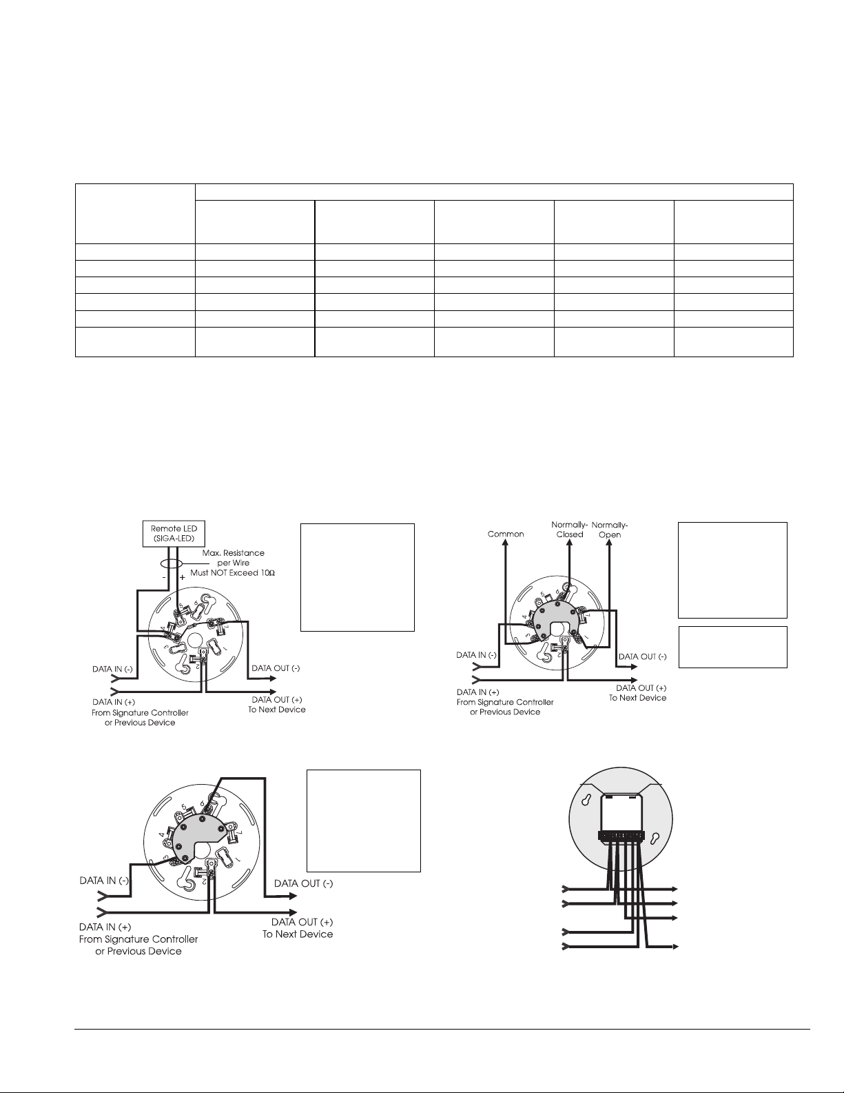
StandardDetector Base,SIGA-SB, SIGA-SB4
Typical Wiring
The detector mounting bases accept #18 AWG (0.75mm2), #16 (1.0mm2), #14 AWG (1.5mm2), and #12 AWG (2.5mm²) wire sizes.
Note: Sizes #16 AWG (1.0mm2) and #18 AWG (0.75mm2) are preferred for ease of installation. See Signature Loop Controller catalog
sheetfor detailed wiringrequirement specifications.
RelayDetector Base,SIGA-RB, SIGA-RB4
Test Fire
Type of Detector
SIGA-IS Ion SIGA-PS Photo
SIGA-HRS and
SIGA-HFS Rate-of
-Rise/Fixed Temp.
SIGA-PHS
Photo/Heat 3D
SIGA-IPHS
Ion/Photo/Heat 4D
Open Wood optimum unsuitable optimum very suitable optimum
Wood Pyrolysis suitable optimum unsuitable optimum optimum
Smouldering Cotton very suitable optimum unsuitable optimum optimum
Poly Urethane Foam very suitable very suitable suitable very suitable optimum
n-Heptane optimum very suitable very suitable optimum optimum
Liquid Fire without
Smoke unsuitable unsuitable optimum very suitable very suitable
IsolatorDetector Base,SIGA-IB, SIGA-IB4
Application
Although photoelectric detectors have a wide range of fire sensing capabilities they are best suited for detecting slow, smoldering fires.
The table below shows six standard test fires used to rate the sensitivity of smoke and heat detectors. The table indicates that no single
sensingelementis suited forall test fires.
EST recommends that this detector be installed according to latest recognized edition of national and local fire alarm codes.
From Power Supply
or Previous Sounder Base
DATA IN (-)
DATA OUT (-)
From Signature Controller
or Previous Device
To Next Sounder Base or
E-O-L Relay
To Next Signature Device
DATA IN (+)
24 VDC IN (+) 24 VDC OUT (+)
24 VDC IN (-) 24 VDC OUT (-)
DATA OUT (+)
DATA (+) IN/OUT
DATA (-) IN
DATA (-) OUT
SIG +
JW1 JW2
SIG -
Jumper JW2
OUT = Steady Tone
IN = Temporal Tone
Jumper JW1
OUT = Low Volume
IN = High Volume
AudibleDetector Base, SIGA-AB4
Term Description
1 Not Used
2 DATA IN/OUT (+)
3 Not Used
4 DATA IN (-)
4 Remote LED (-)
5 Remote LED (+)
6 Not Used
7 DATA OUT (-) CONTACT RATING
1.0 Amp @ 30 VDC
(Pilot Duty)
Term Description
1 Normally Open
2 DATA IN/OUT (+)
3 Common
4 DATA IN (-)
4 Not Used
5 Normally-Closed
6 DATA OUT (-)
Term Description
1 Not Used
2 DATA IN/OUT (+)
3 DATA IN (-)
4 Not Used
5 Not Used
6 DATA OUT (-)
7 Not Used

EST INTERNATIONAL
It is our intention to keep the product information current and accurate. We can not cover specific applications or anticipate all requirements.
All specifications are subject to change without notice. For more information or questions relative to this Specification Sheet, contact EST International.
Printed in Canada
© 1999 EST
Page 4 of 4 Literature Sheet #85001-0269 Issue 5
Accessories
All detector mounting bases have wiring terminals that are
accessible from the “room-side” after mounting the base to the
electrical box. The bases mount to North American 1-gang boxes
and to 3½ inch or 4 inch octagon boxes, 1½ inches (38 mm) deep.
They also mount to European BESA and 1-gang boxes with 60.3
mmfixingcenters. The SIGA-SB4,SIGA-RB4, and SIGA-IB4mount
to North American 4 inch sq. electrical boxes in addition to the
above boxes. They include the SIGA-TS4 Trim Skirt which is used
to cover the “mounting ears” on the base.
Ordering Information
Warnings & Cautions
This detector will not operate without electrical power. As fires
frequentlycause powerinterruption,we suggestyou discussfurther
safeguardswithyour fire protectionspecialist.
Thisdetector will NOTsense fires thatstart inareas where smoke
cannot reach the detector. Smoke from fires in walls, roofs, or on the
opposite side of closed doors may not reach the detector to alarm it.
Catalog Number SIGA-PS
Sensing Element Photoelectric - Light Scattering Principle
Storage &
Operating
Environment
Air Velocity Range: 0 to 5,000 ft/min (0 to 25.39 m/s);
Humidity: 0 to 93% RH, Non-Condensing
Operating Temp: 32ºF to 120ºF (0ºC to 49ºC);
Storage Temp: -4ºF to 140ºF (-20ºCto 60ºC)
Sensitivity Range ULI/ULC - 0.67% to 3.77% obscuration/foot
User Selected
Alarm Sensitivity
Settings
Most Sensitive: 1.0%/ft.; More Sensitive: 2.0%/ft.;
Normal: 2.5%/ft.;
Less Sensitive: 3.0%/ft.; Least Sensitive: 3.5%/ft.
Pre-alarm Sensitivity 5% increments, allowing up to 20 pre-alarmsettings
Operating Voltage 15.2 to 19.95 Vdc (19 Vdc nominal)
Operating Current
Quiescent: 45µA @ 19 V; Alarm: 45µA @ 19 V
Emergency Stand-alone Alarm Mode: 18mA
Pulse Current: 100 µA (100 msec);
During Communication: 9 mA max.
Construction & Finish High Impact Engineering Polymer - White
Compatible
Mounting Bases
SIGA-SB Standard Base, SIGA-RB Relay Base,
SIGA-IB Isolator Base, SIGA-AB Audible Base
LED Operation
On-board Green LED - Flashes when polled;
On-board Red LED - Flashes when in alarm
Both LEDs - Glow steady when in alarm (stand-alone)
Compatible Remote Red LED (model SIGA-LED)
Flashes when in alarm
Compatibility Use With: SIGNATURE Loop Controller
Address Requirements Uses one Device Address
Agency Listings UL, ULC, MEA, CSFM
UL Listed Spacing 30 ft
Catalog
Number Description
Ship Wt.
lbs (kg)
SIGA-PS Intelligent Photoelectric Detector
- UL/ULC Listed .5 (.23)
Accessories
SIGA-SB Detector Mounting Base - Standard
.2 (.09)
SIGA-SB4 4-inch Detector Mounting Base
c/w SIGA-TS4 Trim Skirt
SIGA-RB Detector Mounting Base w/Relay
SIGA-RB4 4-inch Detector Mounting Base w/Relay,
c/w SIGA-TS4 Trim Skirt
SIGA-IB Detector Mounting Base
w/Fault Isolator
SIGA-IB4 4-inch Detector Mounting Base
w/ Fault Isolator, c/w SIGA-TS4 Trim Skirt
SIGA-LED Remote Alarm LED
SIGA-AB4 Audible (Sounder) Base .3 (0.15)
SIGA-TS4 Trim Skirt (supplied with 4-inch bases) .1 (.04)
Specifications
Standard Base SIGA-SB, SIGA-SB4 - This is the basic mounting
base for EST Signature Series detectors. The SIGA-LED Remote
LED is supported by the Standard Base.
Relay Base SIGA-RB, SIGA-RB4 - This base includes a relay.
Normally open or closed operation is selected during installation.
The dry contact is rated for 1 amp (pilot duty) @ 30 Vdc. The relay’s
position is supervised to avoid accidentally jarring it out of position.
The SIGA-RB can be operated as a control relay if programmed to
do so at the control panel (EST3 V.2 only). The relay base does not
supporttheSIGA-LED RemoteLED.
Audible Base SIGA-AB4 - This base is designed for use where
localized or group alarm signaling is required. When the detector
senses an alarm condition, the audible base emits a local alarm
signal. The optional SIGA-CRR Polarity Reversal Relay can be used
for sounding to other audible bases on the same 24 Vdc circuit.
Relay and Audible Bases operate as follows:
- at system power-up or reset, the relay is de-energized
- when a detector is installed in the base with the power
on, the relay energizes for four seconds, then de-energizes
- when a detector is removed from a base with the power on,
the relay is de-energized
- whenthe detectorenters thealarm state,therelayisenergized.
Isolator Base SIGA-IB, SIGA-IB4 - This base includes a built-in line
fault isolator for use on Class A circuits. A detector must be
installed for it to operate. The isolator base does not support the
SIGA-LED Remote LED.
The isolator operates as follows:
- a short on the line causes all isolators to open within 23 msec
- at 10 msec intervals, beginning on one side of the Class A
circuit nearest the loop controller, the isolators close to
provide the next isolator down the line with power
- whenthe isolatornextto theshort closes,reopenswithin 10msec.
The process repeats beginning on the other side of the loop
controller.
Remote LED SIGA-LED - The remote LED connects to the SIGA-SB
or SIGA-SB4 Standard Base only. It features a North American size
1-gang plastic faceplate with a white finish and red alarm LED.
SIGA-TS4 Trim Skirt - Supplied with 4 inch bases, it can also be
ordered separately to use with the other bases to help hide surface
imperfections not covered by the smaller bases.
SIGA-IB
IsolatorBase
SIGA-LED
Remote LED
SIGA-RB
RelayBase
SIGA-SB
StandardBase
SIGA-AB4
Audible Base
This manual suits for next models
1
Table of contents


