SAMUEL JACKSON Argus User manual

!!
Installation!and!Resource!Guide

!
!
!
!
!
!
!
!
!
!
!
!
!
!
!
!
!
!
!
!
!
!
!
!
!
!
!
!
!
!
!
!
!
!
!
!
!
!
!
!
!
!
!

TABLE OF CONTENTS
Argus Installation and Resource Guide
1
1.0 COMPONENTS
1.1 DETECTORS 2
1.2 CONTROL PANEL 3
1.3 POWER CARD 4
1.4 ZONE CARD 6
1.5 ALARM/MONITOR CARD 8
1.6 HORN/STROBE LIGHT 10
2.0 INSTALLATION
2.1 DETECTOR PLACEMENT 11
2.2 INSTALLING DETECTORS 12
2.3 MOUNTING THE PANEL AND SUPPLYING POWER 13
2.4 WIRING ZONE CARDS/DETECTORS 14
2.5 WIRING RELAYS 15
2.6 WIRING HORN/STROBE 16
2.7 TESTING FOR GROUND FAULT 17! !
3.0 START-UP PROCEDURE
3.1 TESTING DETECTORS 18
4.0 OPERATION
4.1 WHAT TO DO IN A SPARK DETECTION SCENARIO 19
5.0 MAINTENANCE
5.1 LENS REPLACEMENT 20
5.2 ROUTINE MAINTENANCE 22
5.3 TROUBLESHOOTING 23
6.0 INSTALLATION GUIDE
6.1 DETECTOR INSTALLATION GUIDE 26
6.2 ELECTRICAL WIRING DIAGRAM 35
7.0 WARRANTY
7.1 WARRANTY 36
!
!

COMPONENTS
Argus Installation and Resource Guide
2
1.0 COMPONENTS
1.1 DETECTORS
The heart of the Argus fire detection is the spark detector. The detector is equipped with
a lens that can see infrared light emitted by extremely small sparks and warn you before
they have a chance to become a fire.
There are two types of detectors, the 343 and 535.
As of 2014 only the 535 detector is available for sale, and all orders for Argus will
include the 535 detector only. Although there are a few changes between the two
detectors, they operate identically. This means that if you choose to replace one of the
old 343 detectors in your gin with a new 535 one, the zone you modified will still work
as before.
The changes between the 343 and 535 detectors that you should be aware of are:
•Mounting dimensions are different. When replacing old detectors, new holes must be
drilled for the mounting brackets.
•The 535 detector has a two-tone LED that indicates whether detector is in an alarm
state (red) or standby (green).
•The End-of-line (EOL) module required for the 343 detector is no longer needed for
the 535. Instead, there is a switch on the 535’s circuit board that should be toggled in
the last detector in a zone. For more information about zone card/detector wiring,
please refer to section 2.4.

COMPONENTS
Argus Installation and Resource Guide
3
1.2 CONTROL PANEL
The control panel houses all the electronics, including the power card, monitor card, zone
cards, and relays. It should be in an accessible location near the gin’s console for easy
access in case of a fire.
The 10-zone panel pictured contains one power card, one monitor card, and room for ten
zone cards.

COMPONENTS
Argus Installation and Resource Guide
4
1.3 POWER CARD
The power card is housed in the top-left slot of the panel and has four indicator lights.
The indicators and adjustments are listed below, some of which are not applicable to
cotton gins. Also included is information on power supply fusing.
•AC Power Indicator (AC Power) on panel door (28 volt bulb): Normally "ON" unless
AC power fails or the bulb fails.
•LED-1 green DC Power Indicator (PWR): Normally "ON" unless fuse F-1 blows (as
long as the battery is connected to the system and fuse F-2 is in the circuit)
•LED-2 green Battery Charged Indicator (CHGD): Not applicable to cotton gin uses.
•LED-3 amber Battery Discharging Indicator (DISCH): Not applicable to cotton gin
uses.
•LED-4 amber Battery Charging Indicator (CHNG): Not applicable to cotton gin uses.
•P-2 Voltage Regulator (Potentiometer): Adjust for 24 volts DC +/- 0.1 volts (measure
across detector output terminals pins 1 & 3) with maximum load on system. Not
applicable to cotton gin uses.
•P-1 Battery Charging Voltage Regulator (Potentiometer): Not applicable to cotton gin
uses.
•SH1 Battery “YES/NO” Indicator: Jumper should be placed on pins towards desired
side.
NOTE: For cotton gin applications, make sure the black jumper is placed on the
pins on the NO side.
Figure: Power Card

COMPONENTS
Argus Installation and Resource Guide
5
Power Supply Fusing:
•F-1 – Battery Charging Fuse (AGC 5 Amperes): This fuse passes both the regulated
and unregulated current when the system goes into battery mode operation. It must
pass current for extinguishers as well as detectors thus it is sized to allow system
operation in event of power disruption. Not applicable to cotton gin uses.
•F-2 – Regulated Power Fuse (GMA 2 Amperes): This fuse controls the regulated 24
volts DC supplied to the circuit boards and detectors. The 2 amperes rating is the
maximum fuse rating for fuses used in this position. Systems with few detectors
and/or zones can use fuses of lesser ratings. Fuses should always be sized to fit the
application or demand current.
•Primary Fuse (GMA 5 Amperes): The primary fuse is located in the AC line
supplying current to the transformer used in the system. The transformer used and the
system configuration or size predicates its size. This fuse passes the entire AC current
demand for the system through a 5 to 1 step-down transformer when a 120 volts AC
line is used. In addition, this fuse must be sized to blow in the event of transformer
failure and/or bridge filter capacitor failure. Typically, the fuse should be a fast blow
5 amperes maximum fuse for maximum power when using a 4 amperes transformer
(120 volts AC to 24 volts DC). The fuse should have a 1 ampere rating when used
with 240 volts AC to 24 volts DC, 4 amperes transformers.

COMPONENTS
Argus Installation and Resource Guide
6
1.4 ZONE CARDS
Each set of detectors is wired to its own zone card located in the control panel. For
information on wiring zone cards, see section 2.4. This section includes a brief overview
of the LED indicators, switches, and fuses located on the card.
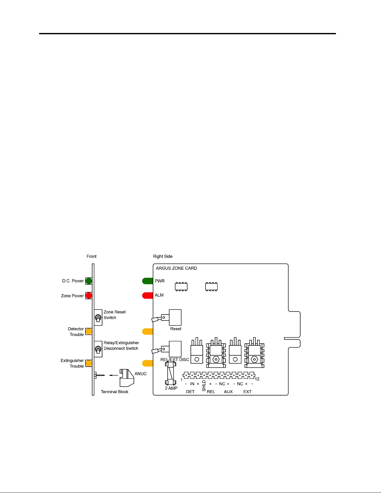
Indicators
•LED #1 – green Power Indicator (PWR): Indicates the presence of 24 volts DC
regulated voltage from the power supply regulator.
•LED #2 – red Alarm Indicator (ALM): Indicates an activation of the alarm circuitry
by the detector.
•LED #3 – amber Detector Trouble Indicator (DET): Indicates trouble in the external
circuits to and from the detector. It will illuminate when the reset switch is operated.
•LED #4 – amber Extinguisher Trouble Indicator (EXT): Indicates trouble in the
extinguisher firing circuit, such as extinguisher disconnect switch being in the open
position, a fuse is blown, open leads, etc.
Switches
•Reset Switch: a normally closed, momentary switch that controls 24 volts DC to the
detectors connected to the zone.
•When operated (moved to the “UP” position), it disconnects the 24 volts DC power
from the detectors, which automatically reset themselves. While operated the amber
indicator will flash and the trouble alert will beep.
Figure: Zone Card

COMPONENTS
Argus Installation and Resource Guide
7
•Extinguisher Disconnect Switch: This switch disconnects the extinguisher and relay
circuits to allow for maintenance. When this switch is in the “UP” position, the
extinguisher amber indicator (EXT) will blink and the trouble alert will beep (unless
silenced) until the switch is returned to the normal “DOWN” position.
Fusing
•The fuse marked F-1 (2 amp) should not be sized greater than 2 amperes.
•Should this fuse blow, the extinguisher and relay power is disconnected and the
amber Extinguisher Trouble Indicator (EXT) will blink.
•Current limiting is provided on the unsupervised relay (terminals 5 and 6) and AUX
relay terminals (8 and 9). The maximum current that will be supplied to these
terminals is 250mA total for the two relays. Current in excess of this amount will shut
down the driving circuit without causing damage to the unit or malfunction of the
alarm circuits.

COMPONENTS
Argus Installation and Resource Guide
8
1.5 ALARM/MONITOR CARD
The Alarm/Monitor card indicates whether the system is working properly or not. If
none of the amber LEDs are lit, then the system should be working properly. This
section goes over the function of each LED and the silence switch.
Indicators
•LED #1 green DC Power Indicator (PWR): Indicates regulated 24 volts DC on card
when illuminated.
•LED #2 amber Alarm Trouble Indicator (ALM): Indicates trouble in the primary
alarm bell circuit.
•LED #3 amber Battery Trouble Indicator (BAT): Indicates battery not in system, SH-
1 on Power Supply Card not in circuit to selected battery, or non-battery operation.
•LED #4 amber Silence Switch Trouble Indicator (SIL): Indicates trouble silence
switch “ON” in 24 v DC circuit on card or ribbon cable.
•LED #5 amber DC Power Trouble Indicator (DC): Indicates trouble in 24 volts DC
circuit on card or on ribbon cable.
•LED #6 amber Ground Fault Trouble Indicator (GDF): Indicates ground fault in
system during installation. This is an installation aid. The system is normally
grounded when operational.
Figure: Alarm/Monitor Card

COMPONENTS
Argus Installation and Resource Guide
9
Silence Switch
•Controls the system trouble beeper. When “UP”, in the silence position, the beeper is
suppressed and only the amber indicator (SIL) and the amber trouble indicating
LED’s will operate. If silence switch is “UP” with no trouble in the system, the
beeper will come on continuously as a reminder that the silence switch needs to be
placed in its normal operating position. This feature also provides an audible
indication to technicians attempting to isolate trouble in the system. When the trouble
is corrected the beeper will emit a continuous tone until the silence switch is returned
to normal.

COMPONENTS
Argus Installation and Resource Guide
10
1.6 HORN/STROBE LIGHT
The horn and strobe combination alerts you when a fire has been detected.
The horn/strobe is wired to the alarm card. It should be placed near the control panel in a
visible location.
For information on wiring the horn/strobe, see section 2.6.

INSTALLATION
Argus Installation and Resource Guide
11
2.0 INSTALLATION
2.1 DETECTOR PLACEMENT
Here is a list of locations that you will want to have your Argus system installed, listed in
order of priority. Keep in mind that the needs of a gin are different from one to the next,
and if you need help choosing locations, contact a Samuel Jackson representative.
•Lint flue – Past all lint cleaners, preferably in round pipe rather than rectangular.
•Gin stands
•Overflow – Right before the separator
•Trash – Before the trash fan
•Seed – Gravity dropper
•Precleaning – Before inclines or separators
•Motes – Before the mote separator/cleaner
•Condenser outlet – Inside the building
Locations to Avoid:
•Immediately after any precleaning equipment
•Near windows
•Near access doors that are opened often
•Near free air gates
Ideally detectors should be installed on access doors to allow for easy maintenance and
periodic cleaning (see 5.2).

COMPONENTS
Argus Installation and Resource Guide
12
2.2 INSTALLING DETECTORS
Here are some general rules to keep in mind when placing detectors in pipe.
•In a horizontal pipe, never put detectors dead bottom center.
•Do not place a detector dead center on the backside of an elbow.
•Typically the detector lens is protruding in the pipe, but spacers can be added if the
lens needs to be recessed out of the pipe.
•Always install detectors in a straight line around a pipe.
•Make sure the detectors are evenly spaced around a pipe.
See the supplemental section at the end of the document for a complete guide to installing
detectors.

INSTALLATION
Argus Installation and Resource Guide
13
2.3 MOUNTING THE PANEL AND SUPPLYING POWER
The control panel houses all the electronics outside of the detectors themselves. When
choosing a location for the panel and providing power to it, keep these things in mind:
•Mount the panel near the console. In case of a fire, you will need to access the panel
to identify the affected zone and access the reset switch. If the panel cannot be close
to the console, it does need to be within eyeshot.
•Power to the panel needs to be dedicated rather than feeding off the power supplied to
another device.
Note: If you have a Moisture Mirror X system in your gin, you have the option of being
able to reset Argus alarms from your Moisture Mirror X with the addition of an Argus
Interface Panel. In this case, the above rules do not necessarily apply. If you have any
questions, please contact a Samuel Jackson representative. For more information, see
Section 6 of the Moisture Mirror X manual.

INSTALLATION
Argus Installation and Resource Guide
14
2.4 WIRING ZONE CARDS/DETECTORS
Wiring zone cards is simple and straightforward. Each new zone card comes with a relay
as well. All that needs to be done is to connect the detectors to the associated zone card.
•Use shielded conduit between detectors and the zone card.
•On the final 535 detector in a zone, toggle the EOL (End-of-Line) switch to
“ON.”
Note: When using the new 535 detectors, it is no longer necessary to use an End-of-
Line module. Instead toggle the EOL switch to “ON” in the last detector in a zone.
Tip: Each zone card comes packaged with and EOL module. It should be removed when
detectors are wired to the card, but in the case that there is a problem with external wiring
or detectors attached to this card, it can be reattached until maintenance is completed and
any issues are solved.
Figure: Wiring for the zone card terminal block
page: 12
1
1
234810 11 12
12
1111
2222
3333

INSTALLATION
Argus Installation and Resource Guide
15
2.5 WIRING RELAYS
Wiring relays involves connecting two wires to the zone card terminal block. Connect
terminal 5 to A1 and connect terminal 6 to A2, according to the figure below.
!
Figure: Alarm relay wiring
•Consult your electrician about tying the relay to equipment that needs to shut
down automatically.
•If a relay needs to be replaced, Samuel Jackson supplies a triple pole double
throw 24V DC relay that is rated to 10 amps.
Note: The resistor between 11 and 12 should be left in place.
page: 12
1
1
234810 11 12
12
1111
2222
3333
A2
A1

INSTALLATION
Argus Installation and Resource Guide
16
Horn Strobe Terminal block
2.6 WIRING HORN/STROBE
Figure: Horn/Strobe circuit board wiring to Alarm/Monitor terminal block
Wiring the Horn/Strobe the Alarm/Monitor card is very simple. There are four wires:
three black wires and one green/yellow grounding wire. Wires 2 and 3 are connected to
the horn, and wires 1 and Ground are connected to the strobe. The wiring inside the
Horn/Strobe is default from the factory. For setup, all that needs to be wired is the
Alarm/Monitor terminal.
Note: The buzzer on the door is also wired into terminals 8 and 9, but this is intentional.
Tip: Alarm/monitor cards come with a resistor attached between terminals 4 and 5,
which work to “fool” the system into thinking a horn is attached. If for some reason the
horn is disconnected, it is useful to keep the resistor. This will prevent the trouble light
from coming on.
INSTALLATION
Argus Installation and Resource Guide
16
2.6 WIRING HORN/STROBE
Figure: Horn/Strobe circuit board wiring to Alarm/Monitor terminal block
Wiring the Horn/Strobe the Alarm/Monitor card is very simple. There are four wires:
three black wires and one green/yellow grounding wire. Wires 2 and 3 are connected to
the horn, and wires 1 and Ground are connected to the strobe. The wiring inside the
Horn/Strobe is default from the factory. For setup, all that needs to be wired is the
Alarm/Monitor terminal.
Note: The buzzer on the door is also wired into terminals 8 and 9, but this is
intentional.
Tip: Alarm/monitor cards come with a resistor attached between terminals 4 and 5,
which work to “fool” the system into thinking a horn is attached. If for some reason the
horn is disconnected, it is useful to keep the resistor. This will prevent the trouble light
from coming on.
1 2 3 4 5 6 7 8 9
HHHHHHHHHHHHHHHGG
Wire 2
Wire 3
Wire 1
Ground
Wire 2
Wire 3
Wire 1
Ground
HHHHHHHHHHHHHHHGG

INSTALLATION
Argus Installation and Resource Guide
17
2.7 TESTING FOR GROUND FAULT
After all detectors have been wired into the control panel and you are performing a final
check of the panel, use this procedure for a ground fault test:
•Monitor Card with Ground Fault Indicator Test Switch:
oDisconnect chassis ground from Terminal #4 on the power card.
oPush the Ground Fault Indicator (GFI) Test Switch on the Alarm Monitor Card.
oRelease the Test Switch and re-connect chassis ground to Terminal #4 on the
Power Card.
•Monitor Card without Ground Fault Indicator Test Switch:
oDisconnect chassis ground from Terminal #4 on Power Card.
oConnect a jumper between Terminal #1 and Terminal #2 on the Alarm Monitor
Card.
oDisconnect the jumper between Terminal #1 and Terminal #2 on Alarm Monitor
Card.
oReconnect the chassis ground to Terminal #4 on the Power Card.
NOTE: If there is a ground in the system, the amber Ground Fault Indicator LED (GDF)
will light on the Alarm Monitor Card. There will be no beeper sound.
If there is not a ground in the system, because there is no trouble signal the amber Ground
Fault Indicator LED (GDF) on the Alarm Monitor Card will not light.

START-UP PROCEDURE
Argus Installation and Resource Guide
18
3.0 START-UP PROCEDURE
3.1 TESTING DETECTORS
•Use a non-LED flashlight or striker to test each detector and assure that each detector
functions properly. If you don’t have an easy access mounting door, then pull off one
sensor to shine the flashlight through that hole.
•Reset the panel after each test to assure that each detector signals the panel properly.
When the detector goes into alarm, the red Alarm Indicator (ALM) on the
corresponding Zone Card should light, and the horn/strobe should come on.
•In the Machine Shutdown relay should trip the stop circuit of the production
machinery intended for stoppage.
•Perform this test after installation of the system and repeat once a year.
Table of contents