DEUTSCHMANN AUTOMATION UNIGATE IC User manual
Instruction Manual
Universal Fieldbus-Gateway
UNIGATE®IC - PROFIBUS
Deutschmann Automation GmbH & Co. KG
www.deutschmann.com | wiki.deutschmann.de

16.5.18 Instruction manual UNIGATE®IC - PROFIBUS DP V. 5.1 3
Deutschmann Automation GmbH & Co. KG
1General introduction . . . . . . . . . . . . . . . . . . . . . . . . 9
2The UNIGATE®IC . . . . . . . . . . . . . . . . . . . . . . . . . 10
2.1 Technical introduction . . . . . . . . . . . . . . . . . . . . . . . . . 10
2.2 Availability . . . . . . . . . . . . . . . . . . . . . . . . . . . . . . . 10
2.3 Firmware . . . . . . . . . . . . . . . . . . . . . . . . . . . . . . . . 10
2.4 The serial standard interface . . . . . . . . . . . . . . . . . . . . . . 10
2.5 The synchronous interface . . . . . . . . . . . . . . . . . . . . . . . 10
2.6 The Debug-interface . . . . . . . . . . . . . . . . . . . . . . . . . . 10
2.7 UNIGATE®IC hardware survey . . . . . . . . . . . . . . . . . . . . 11
3Hardware design. . . . . . . . . . . . . . . . . . . . . . . . . . 12
3.1 Ports . . . . . . . . . . . . . . . . . . . . . . . . . . . . . . . . . . 12
3.2 Pinout . . . . . . . . . . . . . . . . . . . . . . . . . . . . . . . . . 12
3.2.1 -Boot enable . . . . . . . . . . . . . . . . . . . . . . . . . . . . . . 13
3.2.2 Load out (SPI-Master: SS0-) . . . . . . . . . . . . . . . . . . . . . 13
3.2.3 Data out (SPI-Master: SS1-). . . . . . . . . . . . . . . . . . . . . . 13
3.2.4 Data In (SPI: MISO) . . . . . . . . . . . . . . . . . . . . . . . . . . 13
3.2.5 Load In (SPI: MOSI) . . . . . . . . . . . . . . . . . . . . . . . . . . 13
3.2.6 Clock (SPI: SCK) . . . . . . . . . . . . . . . . . . . . . . . . . . . 13
3.2.7 -Reset In . . . . . . . . . . . . . . . . . . . . . . . . . . . . . . . . 13
3.2.8 LED-PB . . . . . . . . . . . . . . . . . . . . . . . . . . . . . . . . 14
3.2.9 -Config Mode . . . . . . . . . . . . . . . . . . . . . . . . . . . . . 14
3.2.10 DbgTX, DbgRx. . . . . . . . . . . . . . . . . . . . . . . . . . . . . 14
3.2.11 TE . . . . . . . . . . . . . . . . . . . . . . . . . . . . . . . . . . . 14
3.2.12 TX, RX . . . . . . . . . . . . . . . . . . . . . . . . . . . . . . . . . 14
3.3 Software . . . . . . . . . . . . . . . . . . . . . . . . . . . . . . . . 14
3.4 Basic line of proceeding . . . . . . . . . . . . . . . . . . . . . . . . 14
3.5 Connection examples . . . . . . . . . . . . . . . . . . . . . . . . . . 15
3.6 Layout examples . . . . . . . . . . . . . . . . . . . . . . . . . . . . 18
3.7 Operation with external PROFIBUS-driver . . . . . . . . . . . . . . . 21
3.8 Termination (PROFIBUS) . . . . . . . . . . . . . . . . . . . . . . . 21
3.9 Handling (mounting the UNIGATE®IC on the carrier board) . . . . . . 21
3.10 Differences between the various versions . . . . . . . . . . . . . . . 22
3.10.1 Standard version. . . . . . . . . . . . . . . . . . . . . . . . . . . . 22
3.10.2 Version "without 485 (PROFIBUS)-driver". . . . . . . . . . . . . . . 22
3.10.3 Version "LWL" . . . . . . . . . . . . . . . . . . . . . . . . . . . . . 22
4The serial interface . . . . . . . . . . . . . . . . . . . . . . . . 23
4.1 Overview . . . . . . . . . . . . . . . . . . . . . . . . . . . . . . . . 23
4.2 Initialization of the serial interface . . . . . . . . . . . . . . . . . . . 23
4.3 Use of the serial interface . . . . . . . . . . . . . . . . . . . . . . . 23
4.4 Further operation modes . . . . . . . . . . . . . . . . . . . . . . . . 23

Deutschmann Automation GmbH & Co. KG
4 Instruction manual UNIGATE®IC - PROFIBUS DP V. 5.1 16.5.18
5Synchronous serial interface . . . . . . . . . . . . . . . . . . . 24
5.1 Shift register operation . . . . . . . . . . . . . . . . . . . . . . . . . 24
5.1.1 Example-Script . . . . . . . . . . . . . . . . . . . . . . . . . . . . 24
5.2 SPI mode . . . . . . . . . . . . . . . . . . . . . . . . . . . . . . . . 25
5.2.1 Example-Script . . . . . . . . . . . . . . . . . . . . . . . . . . . . 25
6The Debug-interface . . . . . . . . . . . . . . . . . . . . . . . . 26
6.1 Overview of the Debug-interface . . . . . . . . . . . . . . . . . . . . 26
6.2 Starting in the Debug-mode . . . . . . . . . . . . . . . . . . . . . . 26
6.3 Communication parameter for the Debug-interface . . . . . . . . . . 26
6.4 Possibilities with the Debug-interface . . . . . . . . . . . . . . . . . 26
6.5 Commands of the Debug-interface . . . . . . . . . . . . . . . . . . 26
7Script and configuration . . . . . . . . . . . . . . . . . . . . . 27
7.1 Overview . . . . . . . . . . . . . . . . . . . . . . . . . . . . . . . . 27
7.2 The configuration mode . . . . . . . . . . . . . . . . . . . . . . . . 27
7.3 Update the script . . . . . . . . . . . . . . . . . . . . . . . . . . . . 27
7.4 Configuration of the UNIGATE®IC . . . . . . . . . . . . . . . . . . . 29
7.4.1 PROFIBUS . . . . . . . . . . . . . . . . . . . . . . . . . . . . . . 29
7.4.2 RS232/RS485/RS422 . . . . . . . . . . . . . . . . . . . . . . . . . 30
8Generating a script . . . . . . . . . . . . . . . . . . . . . . . . 31
8.1 What is a script? . . . . . . . . . . . . . . . . . . . . . . . . . . . . 31
8.2 Memory efficiency of the programs . . . . . . . . . . . . . . . . . . 31
8.3 What can you do with a script device? . . . . . . . . . . . . . . . . . 31
8.4 Independence of buses . . . . . . . . . . . . . . . . . . . . . . . . 31
8.5 Further settings at the Gateway . . . . . . . . . . . . . . . . . . . . 31
8.6 The use of the Protocol Developer . . . . . . . . . . . . . . . . . . . 32
8.7 Accuracies of the baud rates at UNIGATE®IC . . . . . . . . . . . . 32
8.8 Script processing times . . . . . . . . . . . . . . . . . . . . . . . . 33
9PROFIBUS DP . . . . . . . . . . . . . . . . . . . . . . . . . . . 34
9.1 Description of the DPV1- / DPV2-functions . . . . . . . . . . . . . . 34
9.1.1 DPV1 . . . . . . . . . . . . . . . . . . . . . . . . . . . . . . . . . 34
9.1.2 DPV2 . . . . . . . . . . . . . . . . . . . . . . . . . . . . . . . . . 34
9.2 Setting the PROFIBUS-address . . . . . . . . . . . . . . . . . . . . 35
10 Error handling at UNIGATE®IC . . . . . . . . . . . . . . . . . . 37
11 Firmware-update . . . . . . . . . . . . . . . . . . . . . . . . . . 38
11.1 Overview . . . . . . . . . . . . . . . . . . . . . . . . . . . . . . . . 38
11.2 Adjusting the firmware-update-mode . . . . . . . . . . . . . . . . . 38
11.2.1 Adjustment by hardware . . . . . . . . . . . . . . . . . . . . . . . . 38
11.2.2 Adjustment by software . . . . . . . . . . . . . . . . . . . . . . . . 38
11.3 Execution of the firmware-update . . . . . . . . . . . . . . . . . . . 38
11.4 Note on safety . . . . . . . . . . . . . . . . . . . . . . . . . . . . . 38

16.5.18 Instruction manual UNIGATE®IC - PROFIBUS DP V. 5.1 5
Deutschmann Automation GmbH & Co. KG
11.5 Operation mode of the IC . . . . . . . . . . . . . . . . . . . . . . . . 38
12 Technical data . . . . . . . . . . . . . . . . . . . . . . . . . . . 39
12.1 Mechanics of the UNIGATE®IC . . . . . . . . . . . . . . . . . . . . 39
12.1.1 General dimensions of UNIGATE®IC . . . . . . . . . . . . . . . . . 39
12.1.2 Dimensions UNIGATE®IC (PROFIBUS DP only) . . . . . . . . . . 39
12.2 Technical data UNIGATE®IC-PROFIBUS . . . . . . . . . . . . . . . 40
12.2.1 Features of the different versions . . . . . . . . . . . . . . . . . . . 40
13 Accessory . . . . . . . . . . . . . . . . . . . . . . . . . . . . . 41
13.1 Adapter RS232 . . . . . . . . . . . . . . . . . . . . . . . . . . . . . 41
13.2 Adapter RS485 . . . . . . . . . . . . . . . . . . . . . . . . . . . . . 41
13.3 FirmwareDownloadTool (FDT) . . . . . . . . . . . . . . . . . . . . . 41
13.4 Protocol Developer . . . . . . . . . . . . . . . . . . . . . . . . . . . 41
13.5 Developerkit UNIGATE®IC-AB IC . . . . . . . . . . . . . . . . . . . 41
13.5.1 Developerboard UNIGATE®IC-AB . . . . . . . . . . . . . . . . . . 41
13.5.2 Quick start . . . . . . . . . . . . . . . . . . . . . . . . . . . . . . . 42
14 Appendix . . . . . . . . . . . . . . . . . . . . . . . . . . . . . . 43
14.1 Explanations of the abbreviations . . . . . . . . . . . . . . . . . . . 43
14.2 Basis board . . . . . . . . . . . . . . . . . . . . . . . . . . . . . . . 44
14.2.1 Overview basis board PROFIBUS DP. . . . . . . . . . . . . . . . . 44
14.2.2 Connectors of the basis board . . . . . . . . . . . . . . . . . . . . . 48
14.2.2.1 Connector to the external device (RS-interface) . . . . . . . . . . . . . . . 48
14.2.2.2 PROFIBUS DP connector . . . . . . . . . . . . . . . . . . . . . . . . . . 49
14.2.2.3 Power supply of the basis board . . . . . . . . . . . . . . . . . . . . . . . 49
14.2.2.4 Shield terminal lead . . . . . . . . . . . . . . . . . . . . . . . . . . . . . 49
14.2.2.5 Rotary coding switches . . . . . . . . . . . . . . . . . . . . . . . . . . . 49
14.2.2.6 Slide switch (RS485/RS232 interface) . . . . . . . . . . . . . . . . . . . . 49
14.2.2.7 Slide switch (RS485 termination) . . . . . . . . . . . . . . . . . . . . . . 49
14.2.3 Wiring diagram UNIGATE®IC-basis board PROFIBUS DP . . . . . . 50
15 Representation of the data in PROFIBUS DP . . . . . . . . . . 53
15.1 Configuration telegram . . . . . . . . . . . . . . . . . . . . . . . . . 53
15.2 Configuration telegram . . . . . . . . . . . . . . . . . . . . . . . . . 54
15.3 Diagnosis . . . . . . . . . . . . . . . . . . . . . . . . . . . . . . . . 55
15.3.1 Diagnosis in DPV1. . . . . . . . . . . . . . . . . . . . . . . . . . . 57
15.4 Data exchange . . . . . . . . . . . . . . . . . . . . . . . . . . . . . 58
16 Servicing . . . . . . . . . . . . . . . . . . . . . . . . . . . . . . 59
16.1 Returning a device . . . . . . . . . . . . . . . . . . . . . . . . . . . 59
16.2 Downloading PC software . . . . . . . . . . . . . . . . . . . . . . . 59

Deutschmann Automation GmbH & Co. KG
6 Instruction manual UNIGATE®IC - PROFIBUS DP V. 5.1 16.5.18

16.5.18 Instruction manual UNIGATE®IC - PROFIBUS DP V. 5.1 6
Deutschmann Automation GmbH & Co. KG
Disclaimer of liability
We have checked the contents of the document for conformity with the hardware and software
described. Nevertheless, we are unable to preclude the possibility of deviations so that we are
unable to assume warranty for full compliance. The information given in the publication is,
however, reviewed regularly. Necessary amendments are incorporated in the following editions.
We would be pleased to receive any improvement proposals which you may have.
Copyright
Copyright (C) Deutschmann Automation GmbH & Co. KG 1997 – 2018. All rights reserved.
This document may not be passed on nor duplicated, nor may its contents be used or disclosed
unless expressly permitted. Violations of this clause will necessarily lead to compensation in
damages. All rights reserved, in particular rights of granting of patents or registration of
utility-model patents.

Deutschmann Automation GmbH & Co. KG
7 Instruction manual UNIGATE®IC - PROFIBUS DP V. 5.1 16.5.18

16.5.18 Instruction manual UNIGATE®IC - PROFIBUS DP V. 5.1 8
Deutschmann Automation GmbH & Co. KG General introduction
1 General introduction
In the past the integration of a fieldbus connection required an enormous effort from the progress
engineers. On account of the large variety of communication systems it is not enough to compile
the right combination of communication hardware; due to their standards and fundamentals dif-
ferent busses also require the corresponding skills of the engineers.
This does not apply in case of the UNIGATE®IC by Deutschmann Automation any more. All dig-
ital functions, software, stack and driver as well as optocoupler are integrated on a UNIGATE®IC
in correspondence with the standard. In addition to the reduction of the required size, also differ-
ent fieldbusses can easily be integrated.
Through the flexible firmware of UNIGATE®IC no software-changes are required on the
side of the customer!
Since 1997 Deutschmann Automation has experience in the field of fieldbus gateways; this
enormous experience results in the UNIGATE®IC as a consistent sequel of this successful
product line.
Terminology
In the entire document and in all parts of the software that is to be used, the terms Input and Out-
put are used. Input and Output are ambiguous, always depending on the viewpoint. We see the
fieldbus as central interface and as integral component of your device; therefore in all places it is
always referred to data from the viewpoint of the Slave, that is Input data, as data from the Mas-
ter to the Slave - regardless of the used bus.
Representation of numbers
Numbers in decimal format are always represented without prefix and without suffix as well.
hexadecimal numbers are always marked with the prefix 0x.

The UNIGATE® IC Deutschmann Automation GmbH & Co. KG
9 Instruction manual UNIGATE®IC - PROFIBUS DP V. 5.1 16.5.18
2 The UNIGATE®IC
2.1 Technical introduction
The UNIGATE®IC by Deutschmann Automation contains all components that are required for
the communication in a fieldbus in one single module. Therefore a developer does not have to
take care for that detail any more, only a hardware redesign is necessary in order to integrate the
UNIGATE®IC and the required plug connectors.
2.2 Availability
The module is available as PROFIBUS DP. Further fieldbusses are either planned or being
worked on. They will only differ in the connections of the busses. The meaning of the general
pins 1 - 9 as well as 24 and 26 - 32 will remain unchanged also for further fieldbus implementa-
tions.
You can find an up-to-date list for all UNIGATE®ICs under:
http://www.deutschmann.com.
2.3 Firmware
UNIGATE®IC is programmed via scripts. On principle any script, that has been developed for a
UNIGATE®SC, can also be operated on the UNIGATE®IC.
2.4 The serial standard interface
Intelligent devices, that already feature a micro controller or a microprocessor, are generally sup-
plied with a serial asynchronous interface with a TTL-level. It is directly connected with the TTL-
interface of the UNIGATE®IC. For more information on this serial interface see chapter 4 on
page 22.
2.5 The synchronous interface
In addition to the standard interface there is also the possibility of the synchronous input and out-
put. That way for instance digital IOs can be connected through shift register components or also
analog IOs can be connected through a DA-converter with serial in-/output. For synchronous IOs
256 signals at the most can be used (256 bit). Wiring examples can be found in chapter 3.5 on
page 14 and for software examples see chapter 5. This interface can also be used to connect
modules or devices with SPI-interface. It is also possible to build, for instance digital or analo-
gous I/O-modules, with the customer’s device not being equipped with an own controller. The
fieldbus IC is also operable autonomously without that controller.
2.6 The Debug-interface
The UNIGATE®IC features a Debug-interface, which allows to process a script step by step and
also to monitor or manipulate data. This is indispensable for the development of a script. Usually
a script is developed with the software Protocol Developer. For more details take a look at the
instruction manual Protocol Developer.
All interfaces can independently be used at the same time.

16.5.18 Instruction manual UNIGATE®IC - PROFIBUS DP V. 5.1 10
Deutschmann Automation GmbH & Co. KG The UNIGATE® IC
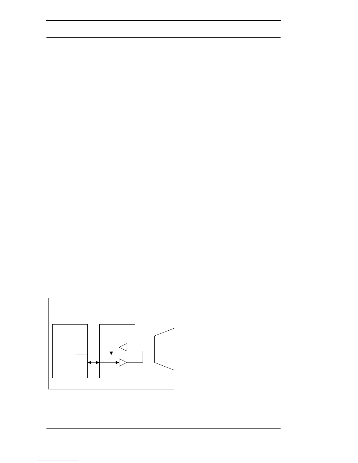
2.7 UNIGATE®IC hardware survey
The hardware of the UNIGATE®IC consists of some few standard components. The picture
below shows the functional structure of the IC.
UART 1 UART 2 SYN.SERIAL
Microcontroller
Flash-ROM
RAM
EEROM
DC
DC
Opto Coupler
Fieldbus-Interface
I
so
l
at
i
o
n
T
E
N
T
X
R
X
R
X
T
X
CLOCK
LOAD
OUT
DATA
OUT
DATA
IN
LOAD
IN

Hardware design Deutschmann Automation GmbH & Co. KG
11 Instruction manual UNIGATE®IC - PROFIBUS DP V. 5.1 16.5.18
3 Hardware design
This chapter gives basic advise, that is required in order to load UNIGATE®IC into your own
hardware designs. In the following all ports of UNIGATE®IC are described in detail.
3.1 Ports
UNIGATE®IC features 32 pins in its layout as a DIL 32 component. Pin 10 -12 and 21 - 23 as
well are not wired due to the electrical isolation. The exact mechanical dimensions can taken
from chapter 12 on page 38.
In the layout boreholes for ALL 32 pins have to be planned.
3.2 Pinout
Pin Technical
specifications
Name Description Remark
15V ± 5% < Typ 170mA
3.3V ± 5% < Typ 170mA
Vcc + 5 V voltage supply
+ 3.3V voltage supply (optionally
at PBL)
see chapter 12.2.1 on page 39
2INLogic -BE boot enable
3OUTDriver Load out
(SS0-)
strobe signal for synchronous,
serial interface
4OUTDriver Data out
(SS1-)
output data for synchronous,
serial interface
5INLogic Data in
(MISO)
input data of the synchronous,
serial interface
internally pulled up with 10 k
6OUTLogic Load in
(MOSI)
input data of the synchronous,
serial interface; alternatively
strobe signal of the output data
7OUTDriver Clock clock pulse signal for synchro-
nous, serial interface
8INReset -Reset in reset-input of the IC internally pulled up with 100 k
9connected to pin 1 Vcc + 5 V voltage supply
10-12 nc nc no pin available
13* according to norm PB-A
TxPB1)
PROFIBUS-signal according to
standard
galvanically isolated
insulation voltage 1000 Vrms
14* according to norm PB-B
RxPB1)
PROFIBUS-signal according to
standard
galvanically isolated
insulation voltage 1000 Vrms
15* according to norm PB-RTS PROFIBUS-signal according to
standard
galvanically isolated
insulation voltage 1000 Vrms
16-18 according to norm nc not connected
19* according to norm PB-GND PROFIBUS-signal according to
standard
galvanically isolated
insulation voltage 1000 Vrms
20* according to norm PB-5V PROFIBUS-signal according to
standard
galvanically isolated
insulation voltage 1000 Vrms
21-23 nc nc no pin
24 connected to pin 32 GND ground supply voltage of the IC
25 OUTTristate LED-PB bus error LED of the PROFIBUS 8 mA, internal series resistor
5V = 1.5 kVR
26 INLogic -Config Mode signal to start the configuration
mode
internally pulled up with 10 k
27 OUTLogic DbgTX serial Debug TX
28 INLogic DbgRX serial Debug RX internally pulled up with 10 k
29 INLogic RX serial data RX internally pulled up with 10 k
30 OUTLogic TX serial data TX

16.5.18 Instruction manual UNIGATE®IC - PROFIBUS DP V. 5.1 12
Deutschmann Automation GmbH & Co. KG Hardware design
The PROFIBUS signals are galvanically isolated. The insulation voltage is 1000 Vrms.
1) Version without 485 (ROFIBUS) - driver (see chapter 3.7 and chapter 3.10.2).
*) The version “LWL“ (without galvanic isolation on the PROFIBUS-side) has the TTL-signals directly avai-
lable at the pins 13, 14 and 15. The pins 19 and 20 are not connected, since for the LWL-version no galva-
nic separated PROFIBUS-voltage is required or it is generated by itself (see chapter 3.10.3).
5V ± 5%, < 250mA VIL VIH
INReset < 0.3V / 5mA >1.95V / 10µA
INLogic < 0.8V / 0,5mA >1.95V / 10µA
VOL VOH
OUTLogic < 0.6V / 1mA >3.8V / 0.1mA
OUTDriver < 0.33V / 4mA >3.8V / 4mA
3.3V ± 5%, < 250mA VIL VIH
INReset < 0.2V / 4mA >1.5V / 10µA
INLogic < 0.5V / 0.4mA >1.5V / 10µA
VOL VOH
OUTLogic < 0.6V / 1mA >2.3V / 0,1mA
OUTDriver < 0.5V / 4mA >2.5V / 4mA
3.2.1 -Boot enable
The IC is started in the firmware update mode with the level GND during the power up process.
See also chapter 11 on page 37.
3.2.2 Load out (SPI-Master: SS0-)
Strobe signal for the synchronous serial interface. With the positive edge at this output data is
taken from the connected shift registers to the physical outputs.
In SPI mode this Pin serves as a low-active Slave-Select-Signal.
3.2.3 Data out (SPI-Master: SS1-)
On this line data is output on the synchronous serial interface. The most significant bit of the data
is output first.
In SPI mode this Pin serves as a low-active Slave-Select-Signal.
3.2.4 Data In (SPI: MISO)
Data is read in on the synchronous serial interface via this signal. The most significant bit of the
data is expected first.
In SPI mode this Pin serves as data transfer from Slave to Master.
3.2.5 Load In (SPI: MOSI)
This pin is the strobe signal for the input data of the synchronous serial interface.
In SPI mode this Pin serves as data transfer Master to Slave.
3.2.6 Clock (SPI: SCK)
This signal is the clock line for the synchronous serial interface. That signal is equally valid for
data input and data output.
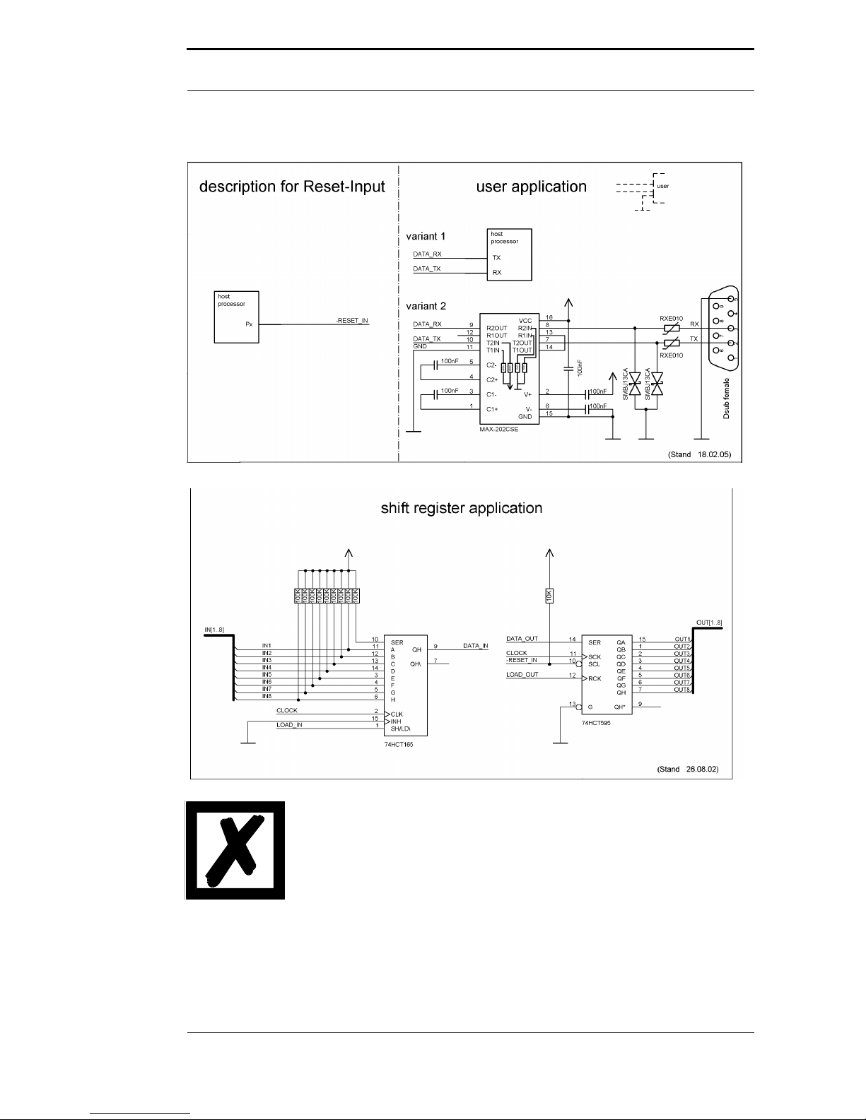
3.2.7 -Reset In
•A reset generator (Max 809) is on board; with it in the normal case the reset input is not
required. In this case the reset input has to be connected with VCC, in order to avoid interfer-
ences (see chapter 3.6).
31 OUTLogic TE transmit enable
32 GND GND ground supply voltage of the IC
Hardware design Deutschmann Automation GmbH & Co. KG
13 Instruction manual UNIGATE®IC - PROFIBUS DP V. 5.1 16.5.18
•If the customer’s application has to initiate a reset of the UNIGATE®IC, then the reset input can
also be connected with a reset output of the customer’s application instead of connecting it with
VCC. Here all specifications of the reset signal, mentioned in chapter 3.2 have to be kept. The
reset-impulse is supposed to last at least 10 ms.
3.2.8 LED-PB
A red LED can be connected to this line. It is controlled by the PROFIBUS ASIC and goes out in
the state „Data Exchange“. (see chapter 3.6)
3.2.9 -Config Mode
If the pin has the level GND, then the IC starts in the configuration mode.
3.2.10 DbgTX, DbgRx
They are transmission line and receive line as well of the IC’s Debug-interface. For the function
description of the Debug-interface see chapter 6.
3.2.11 TE
The Transmit Enable Signal allows the connection of RS485 drivers to the IC’s serial interface.
The signal is set to High whenever the IC sends via the line TX.
3.2.12 TX, RX
Transmission and receive line of the serial interface. This interface is programmable in accor-
dance with the description in chapter 4.
3.3 Software
The software executes script-commands, which in turn control the IC’s hardware and they pro-
cess their complete protocol by software. The script itself can be generated by the company
Deutschmann Automation or with the software Protocol Developer by yourself. For a detailed
description of the script.commands of the Protocol Developer see the instruction manual Proto-
col Developer and the online documentation concerning script-commands.
3.4 Basic line of proceeding
In theory it is enough to replace the RS232-driver that is included in your application by the UNI-
GATE®IC.
.
. .
. .
. .
. .
Customer
Processor
U
A
R
T
Max 232
9-pol DSUB
RS232

16.5.18 Instruction manual UNIGATE®IC - PROFIBUS DP V. 5.1 14
Deutschmann Automation GmbH & Co. KG Hardware design
Your device, which on the whole is supposed to be assembled as shown above, will now be mod-
ified in a way that the PROFIBUS is available at the 9-pol. socket. However, a hardware redesign
is necessary in order to keep the assignment in standard form.
Customer
Processor
U
A
R
T
U
A
R
T
UNIGATE®-IC
.
. .
. .
. .
. .
9-pol-DSUB
Profibus
After the RS232-driver has been replaced by the UNIGATE®IC, the PROFIBUS is available at
the 9-pol. D-sub-socket.
Deutschmann Automation is also offering an appropriate adapter board. With it existing devices
can be adapted without re-design; see chapter 13.
3.5 Connection examples
Here you will find some advise that offers help for a re-design. In the following several versions
are listed, that should make it easier for you to decide.
Version 1: Use as a pure link module for the bus
Microcontroller
UART
UNIGATE
IC
Profibus
U
A
R
T
1
U
A
R
T
2
S
Y
N
S
E
R
N
ot used
N
ot used
.
. .
. .
. .
. .
D-Sub
Profibus
The UNIGATE®IC independently processes the communication with the customer’s device via
the TTL-interface.
Hardware design Deutschmann Automation GmbH & Co. KG
15 Instruction manual UNIGATE®IC - PROFIBUS DP V. 5.1 16.5.18
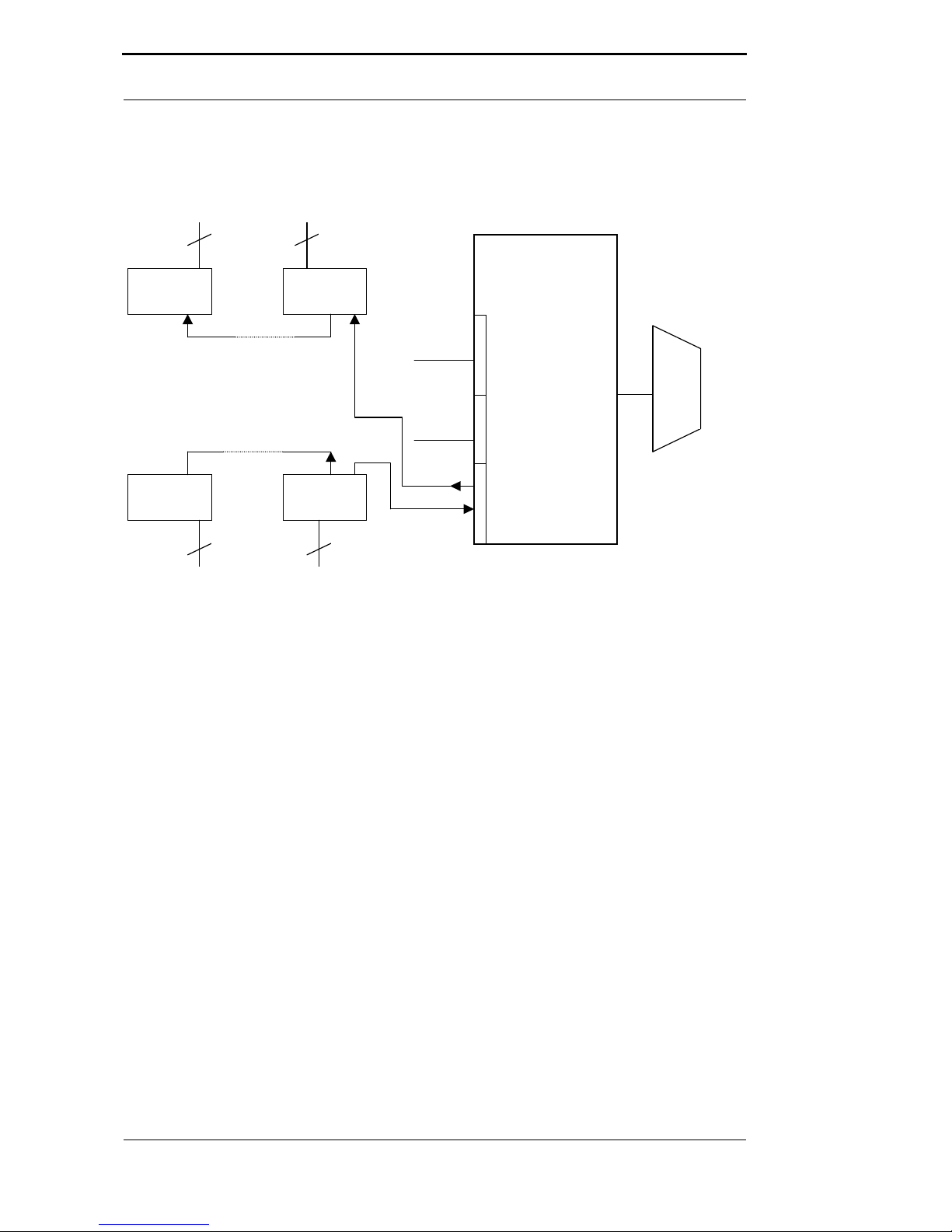
Version 2: Use of UNIGATE®IC for digital or analog I/O-modules
UNIGATE
IC
Profibus
U
A
R
T
1
U
A
R
T
2
S
Y
N
S
E
R
.
. .
. .
. .
. .
D-Sub
Not used
Not used
SR SR
SR SR
8
8
Out N-M Out 1-8
8 8
IN N-M IN 1-8
Here only the synchronous serial interface is used, the asynchronous serial interface is basically
of no account. If you want to program the script in your completed application, then the use of a
connector for the asynchronous interface is recommended. With it you can carry out the ISP-pro-
gramming.
For this operating mode no additional controller is required on your application!
16.5.18 Instruction manual UNIGATE®IC - PROFIBUS DP V. 5.1 16
Deutschmann Automation GmbH & Co. KG Hardware design
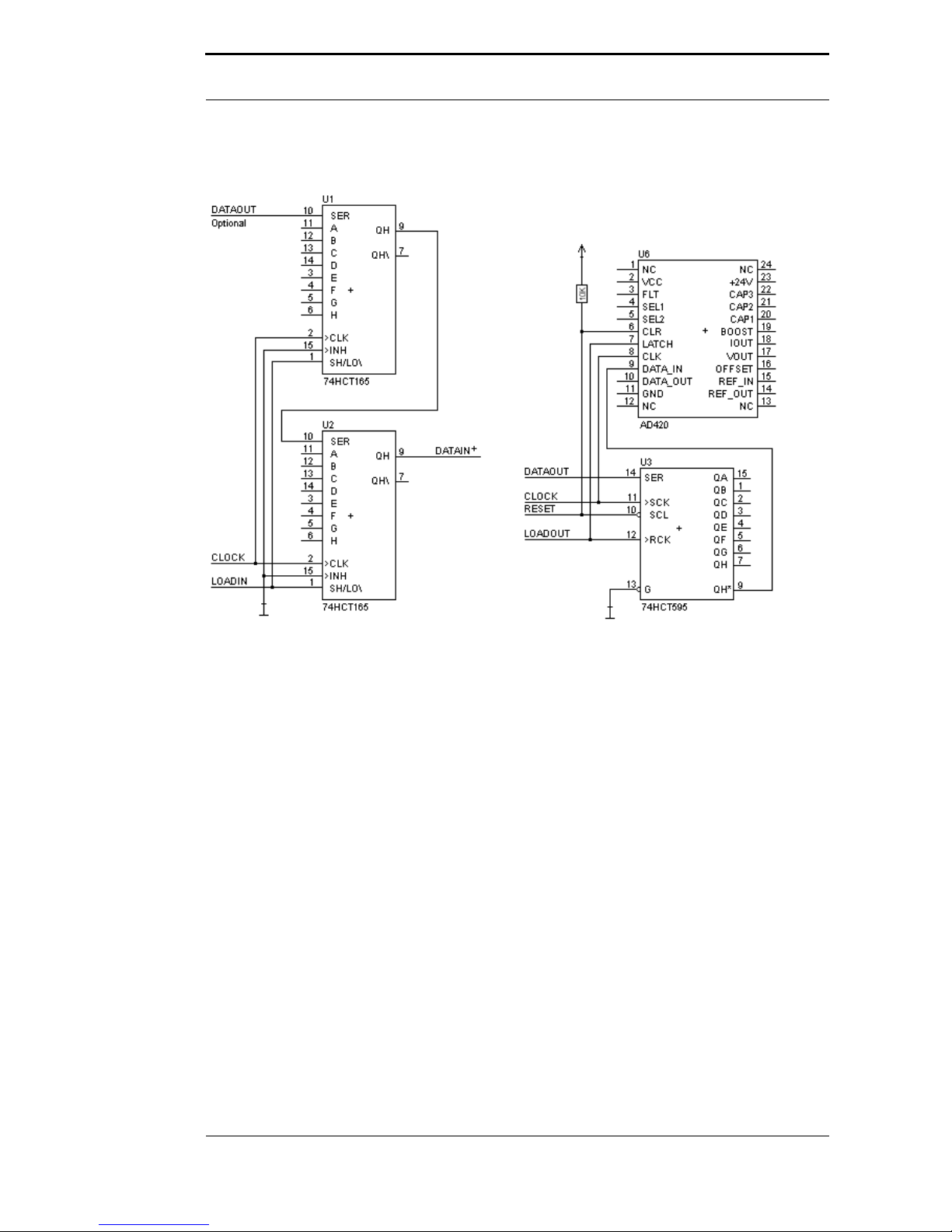
The following circuit diagram is an example for how shift register components can be connected
to the IC.
Version 3: Example for digital I/Os
The serial synchronous and the asynchronous interface as well can be operated by UNIGATE®
IC at the same time. Here the possibility results that an existing application can be extended by
additional digital or analog I/Os.
In chapter 5.2 you find an example for a script, that operates these I/Os.

Hardware design Deutschmann Automation GmbH & Co. KG
17 Instruction manual UNIGATE®IC - PROFIBUS DP V. 5.1 16.5.18
Valid for all versions: A planed plug connection of the serial interface in the application offers the
possibility of an update of the firmware or the software via an external connection.
UNIGATE
IC
Profibus
U
A
R
T
1
U
A
R
T
2
S
Y
N
S
E
R
.
. .
. .
. .
. .
D-Sub
customer
processor UART
connecto
r
connecto
r
IN
Out
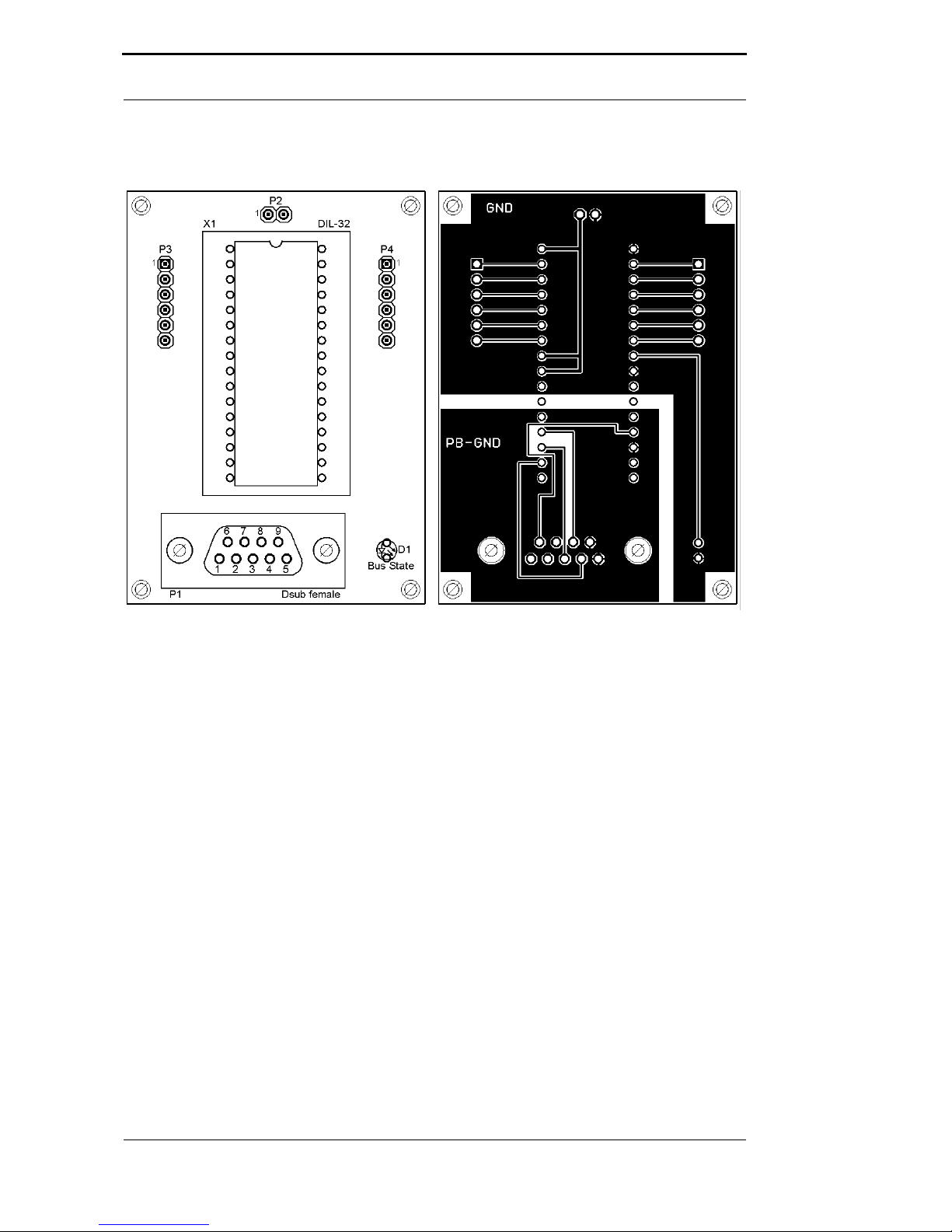
3.6 Layout examples
The connection of the two PROFIBUS-lines (PB+ and PB-) are to be
implemented as short as possible, in order to avoid reflections and with
it disturbances on the PROFIBUS line!
If these stub-lines (PB+ and PB-)are too long, communication problems
may arisewhen operating at higher bus speeds (>1.5 Mbaud). According
to the PROFIBUS Test Specification, the max. allowed total length of all
stub-lines on a bus segment is 80mm at 12 Mbaud. Over a full bu sseg-
ment of 32 nodes this equals 25mm.
16.5.18 Instruction manual UNIGATE®IC - PROFIBUS DP V. 5.1 18
Deutschmann Automation GmbH & Co. KG Hardware design
The 74HCT595 used in this example has an undefined on-position, but
therefor can set the outputs to the tri-state condition via the OutEnable-
Pin 13. If it is more important to have a defined on-position in an applica-
tion, and the OutEnable-pin is not necessary, the 74HCT594 can be used
here.
Hardware design Deutschmann Automation GmbH & Co. KG
19 Instruction manual UNIGATE®IC - PROFIBUS DP V. 5.1 16.5.18
16.5.18 Instruction manual UNIGATE®IC - PROFIBUS DP V. 5.1 20
Deutschmann Automation GmbH & Co. KG Hardware design
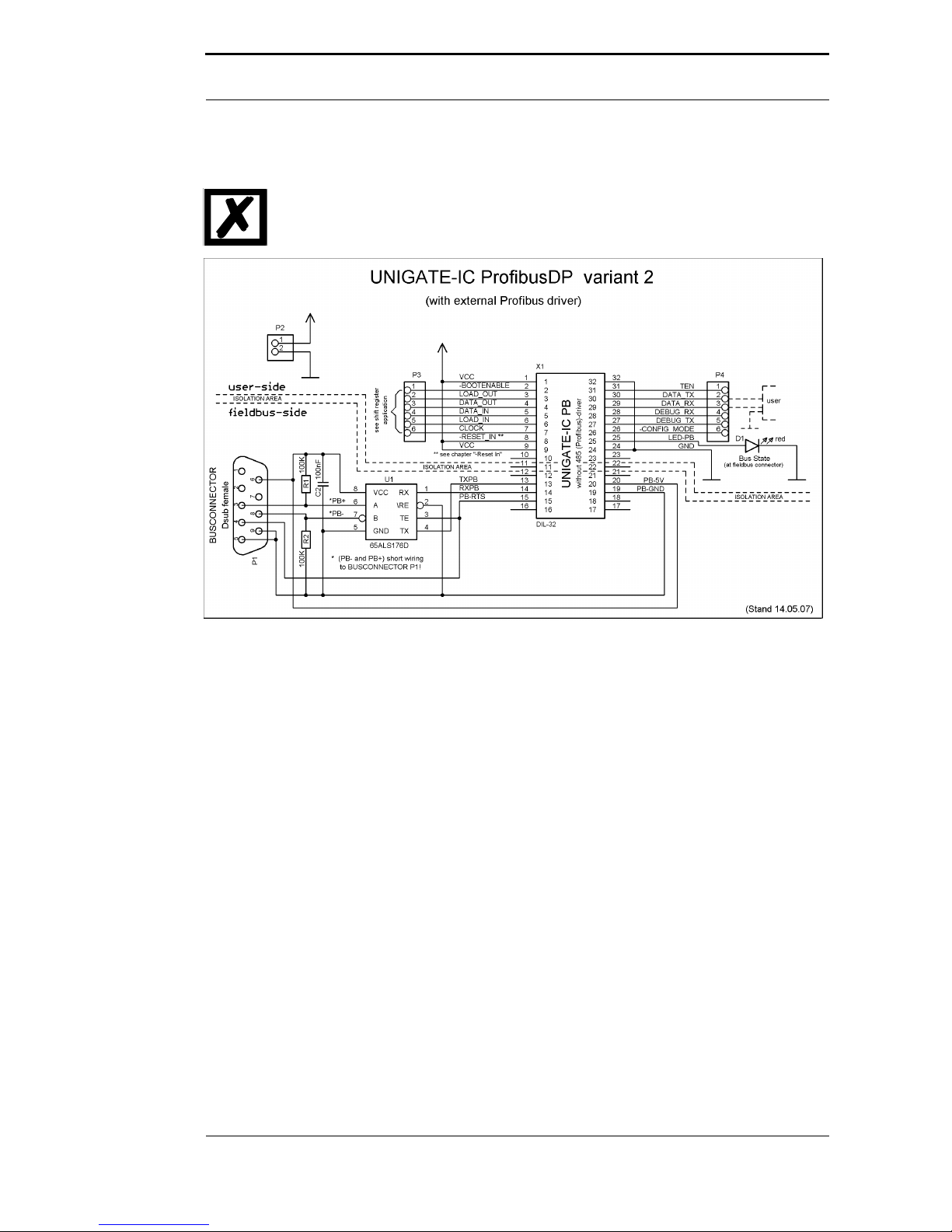
3.7 Operation with external PROFIBUS-driver
Note: Only in connection with IC-version “without 485 (PROFIBUS) - driver“.
3.8 Termination (PROFIBUS)
Generally it is recommended to use a PROFIBUS connector with integrated bus termination. If
this is not possible a switchable terminating resistor (220 R) can be integrated on the carrier
board. In this case furthermore a Pull-Down-resistor (390 R) to PB-GND and a Pull-Up-resistor
(390 R) to PB-5V has to be intergrated.
3.9 Handling (mounting the UNIGATE®IC on the carrier board)
Depending on the application and the expected shock- and vibration-conditions you can choose
from the following possibilities for the UNIGATE®IC’s installation on the carrier board:
•Mounting on a socket in the carrier board. If necessary solder the UNIGATE®IC to 2 or 4 pins
in the socket. Normally the IC can easily be pulled out after the soldering points have been re-
moved.
•Make arrangements for two holes next to the socket in the layout. After the UNIGATE®IC was
plugged in the socket pull an isolated wire over the IC and solder it on the carrier board at the
specified holes.
•Fasten the UNIGATE®IC With a wire or a tie wrap on the socket.
•Manual soldering directly on the carrier board.
•Automatic soldering directly on the carrier board, whereas „selective“ soldering is essential (no
wave soldering)
Other manuals for UNIGATE IC
1
This manual suits for next models
3
Table of contents
Popular Motherboard manuals by other brands


ON Semiconductor
ON Semiconductor AP0101AT user manual

mikroElektronika
mikroElektronika TouchKey click manual

ADLINK Technology
ADLINK Technology CoreModule 740 Reference manual

Chassis Plans
Chassis Plans MTXP-945G Technical reference

Gigabyte
Gigabyte GA-P55-UD3L user manual

Supero
Supero X9DRL-3F user manual