DEWESOFT DS-16xLVDTr Product manual

DS-16xLVDTr
TECHNICAL REFERENCE MANUAL
V1.0
1

TECHNICAL REFERENCE MANUAL
DS-16xLVDTr
Table of contents
1. About this document 3
1.1. Legend 3
1.2. Online versions 4
1.2.1. DS-16xLVDTr technical reference manual 4
1.2.2. DEWESoft® tutorials 4
2. System Overview 5
2.1. Main features 6
3. Specifications 7
3.1. General 7
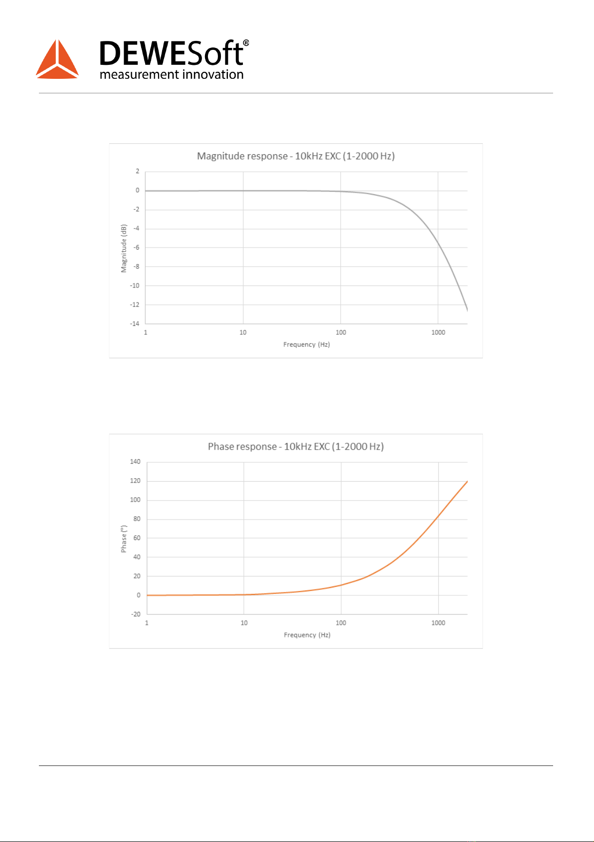
3.2. Output bandwidth - Magnitude and Phase response 8
4. Theory of operation 10
5. SYNC inputs 12
5.1. Sync input to LVDT-EXC transfer function 13
6. Sensor inputs 14
6.1. Pinout 15
6.2. Typical Full Bridge sensor connection 16
6.3. Typical Half Bridge sensor connection 17
7. Adapter outputs 19
7.1. Pinout 20
7.2. Typical connection to DEWESoft amplifier w. DSUB-9 connector 21
8. Safety instructions 22
8.1. General Safety Instructions 22
8.1.1. Environmental Considerations 22
8.1.2. Product End-of-Life Handling 22
8.1.3. General safety and hazard warnings for all Dewesoft systems 23
9. Notice 25
9.1. Warranty Information 25
9.2. Calibration 25
9.3. Support 25
9.4. Service/repair 25
9.5. Restricted Rights 26
9.6. Printing History 26
9.7. Copyright 26
9.8. Trademarks 26
9.9. Documentation version 27
V1.0
2 / 27

TECHNICAL REFERENCE MANUAL
DS-16xLVDTr
1. About this document
This is the Technical Reference Manual for DS-16xLVDTr Version 1.0.0 .
1.1. Legend
The following symbols and formats will be used throughout the document.
Important
Gives you an important information about a subject.
Please read carefully!
Hint
Gives you a hint or provides additional information about a subject.
Example
Gives you an example to a specific subject.
Safety symbols in the manual:
Warning
Calls attention to a procedure, practice, or condition that could cause the body injury or death
Caution
Calls attention to a procedure, practice, or condition that could possibly cause damage to
equipment or permanent loss of data.
V1.0
3 / 27

TECHNICAL REFERENCE MANUAL
DS-16xLVDTr
1.2. Online versions
1.2.1. DS-16xLVDTr technical reference manual
The most recent version of this manual can be downloaded from our homepage:
https://download.dewesoft.com/list/manuals-brochures/hardware-manuals
In the Hardware Manuals section click the download link for the DS-16xLVDTr technical reference
manual .
1.2.2. DEWESoft® tutorials
The DEWESoft® tutorials document, provides basics and additional information and examples for
working with DEWESoft® and certain parts of the program.
The latest version of the DEWESoft® tutorials can be found here:
https://download.dewesoft.com/list/manuals-brochures/software-manuals
In the Software Manuals section click the download link of the DEWESoft X3 tutorials entry.
Important
Read safety instructions first in chapter 8. Safety instructions .
V1.0
4 / 27

TECHNICAL REFERENCE MANUAL
DS-16xLVDTr
2. System Overview
DS-16xLVDTr
Combines 16 channels of LVDT signal conditioners in a 19”-rack housing with 1U height.
LVDT
Strain / Stress
Full Bridge
Half Bridge
DSI Compatible
TEDS Compatible
IP20
-20 °C to +50 °C
V1.0
5 / 27

TECHNICAL REFERENCE MANUAL
DS-16xLVDTr
2.1. Main features
●LVDT SENSOR INTERFACING: DS-16xLVDTr uses a unique ratiometric architecture to eliminate
several of the disadvantages associated with traditional approaches to LVDT interfacing.
DS-16xLVDTr combines 16 channels of DSI-LVDT adapters in a 19”-rack housing with 1U height.
●SYNCHRONISATION: Main advantage of new design is a synchronous excitation signal provided
from external function generator to a BNC front connector (IN connector). When using multiple
DS-LVDTr devices the EXC signal can be daisy-chained from the BNC OUT connector to the BNC
IN connector on the other device.
●CONNECTIVITY: Additionally, there are 16 DSUB-9M (male) connectors on the front panel of
DS-16xLVDTr for the connection to the Dewesoft host amplifier. By each connector is a trimmer
used for phase adjustment. On the back panel are 16 DSUB-9F (female) connectors for the sensor
connection. DS-16xLVDTr supports measurements with full-bridge and half-bridge LVDT sensor
types.
V1.0
6 / 27

TECHNICAL REFERENCE MANUAL
DS-16xLVDTr
3. Specifications
3.1. General
Parameter
Description
Power supply Exc. Voltage
10V – 15V, from EXC+ to EXC- outputs
(SIRIUS STGv2 = 15V supply)
Power consumption per
channel
320mW (15V supply, no load)
800mW (15V supply, 100R load on 3Vrms)
Output voltage max.
500mV for 1000mV/V HB LVDT
Output bandwidth
1kHz (-6dB, 90deg phase)
Gain error
1% of Full Scale
Output TCR
55ppm/K of Full Scale
Sensor supported type
Full Bridge / Half-Bridge LVDT
impedance min. 120R.
SYNC Input Voltage
500mVrms typical recommended
1700mVrms max recommended
Sensor Exc. voltage
3Vrms max (15V supply)
set on SYNC Inputs:
1.76 * Sync Input (Vrms) @ 4kHz
1.70 * Sync Input (Vrms) @ 10kHz
Sensor Exc. frequency
4kHz to 10kHz typical, set on SYNC Inputs
Phase compensation
-50° to +85° @ 4kHz
-75° to +70° @ 10kHz
TEDS
1024-Bit, 1-Wire EEPROM
Operating temperature
-20°C to +50°C
Ingress protection
IP20
Humidity
5% to 85% RH non condensing @ 50°C
Dimensions
444 x 221 x 44 mm (W x D x H)
Weight
2300g
V1.0
7 / 27

TECHNICAL REFERENCE MANUAL
DS-16xLVDTr
3.2. Output bandwidth - Magnitude and Phase response
Typical magnitude response for 4kHz EXC
Typical phase response for 4kHz EXC
V1.0
8 / 27

TECHNICAL REFERENCE MANUAL
DS-16xLVDTr
Typical magnitude response for 10kHz EXC
Typical phase response for 10kHz EXC
V1.0
9 / 27

TECHNICAL REFERENCE MANUAL
DS-16xLVDTr
4. Theory of operation
DS-16xLVDTr Adapter uses a unique ratiometric architecture to eliminate several of the disadvantages
associated with traditional approaches to LVDT interfacing. The benefits of this new circuit are: minimal
adjustments are required; temperature stability is improved; and transducer interchangeability is
improved.
Functional block diagram of a single shannel of DS-16xLVDTr adapter
DS-16xLVDTr adapter SENSE inputs are connected as B-Inputs and adapters IN are connected as
A-Inputs. Phase Lead / Lag circuit will compensate difference of the sensor output in reference to Exc.
and Sense inputs.
V1.0
10 / 27

TECHNICAL REFERENCE MANUAL
DS-16xLVDTr
Output signal level will depend on the phase difference between the sensor output and Sense inputs.
LVDT adapter output sensitivity to input signal phase lead/lag, 1:1 sensor
Two examples are shown for sensor with sensitivity = 0,5. Output signal level is of the Exc. Signal. Sensor
output phase lag is 45⁰. LVDT adapter output is ≈0,35 (≈1Vexc ∙ sensitivity ∙ 0,70).
When phase compensation matches phase lead / lag of sensor output LVDT adapter output will be at its
maximum = 0,5 (=1Vexc ∙ sensitivity ∙ 1,00).
Example: 45⁰ sensor output, no compensation
Example: 45⁰ sensor output, 45⁰ compensation
V1.0
11 / 27

TECHNICAL REFERENCE MANUAL
DS-16xLVDTr
5. SYNC inputs
2x BNC SYNC input connectors
BNC SYNC input pinout
Parameter
Description
Comment
Input connectors
2 x BNC
Parallel, Not isolated
Coupling
AC - High pass
-3dB @ 16Hz (1st order)
Input impedance
1MR
Overvoltage Protection / ESD
36V
Bidirectional TVS
Overcurrent Protection
2.4mA typical
Resettable
Input Bandwidth
4kHz
10kHz
20kHz
Att: 0%
17deg phase relative to input
Att: <2%
45deg phase relative to input
-3dB @ 20kHz (2nd order)
V1.0
12 / 27

TECHNICAL REFERENCE MANUAL
DS-16xLVDTr
5.1. Sync input to LVDT-EXC transfer function
Table of Transfer Coefficients:
Parameter
Output @4kHz (Vrms)
Output @4.8kHz (Vrms)
Output @10kHz (Vrms)
Transfer-K
1.76
1.76
1.7
Sensor LVDT-EXC Output equation:
V DT XC Output (V rms)T ransfer Sync Input (V rms) L−E= −K*
Influence on Noise floor
Noise floor may differ with Sync Input Voltage level. Adjust if required.
V1.0
13 / 27

TECHNICAL REFERENCE MANUAL
DS-16xLVDTr
6. Sensor inputs
LVDT sensor inputs are located on the back side
Parameter
Description
Comment
Connectors
16 x DSUB-9 female
Not isolated
Sensor Probe type
Half Bridge / Full Bridge
Optional: Internal HB
termination on In-
V1.0
14 / 27

TECHNICAL REFERENCE MANUAL
DS-16xLVDTr
6.1. Pinout
Pin Assignment DSUB9-female
1: Sensor supply, excitation +
2: Sensor Output +
3: Sense -
4: Ground
5: Not Connected
6: Sense +
7: Sensor Output -
1.
8: Sensor supply, excitation -
9: Reserved
Important
Optional internal HB completion: Do not connect Sensor Output-. Pin-7 internally terminated as
Half-Bridge. Must specify when ordered!
V1.0
15 / 27

TECHNICAL REFERENCE MANUAL
DS-16xLVDTr
6.2. Typical Full Bridge sensor connection
Note
6-wire connection only shown. 4-wire also possible, connect Sns and Exc signals on adapter side
of connector.
V1.0
16 / 27

TECHNICAL REFERENCE MANUAL
DS-16xLVDTr
6.3. Typical Half Bridge sensor connection
External Half Bridge completion
Optional internal Half Bridge completion
Important
Input - (pin7) shall be connected to half bridge completion resistor divider assembled with
discrete resistors with the following recommended specifications:
●Resistance 1kΩ,
●Tolerance 0.1%,
●Temperature coefficient 15ppm,
●Power 0,125W.
This connection is preferred over the connection IN- to GND (so called “noisy GND”).
V1.0
17 / 27

TECHNICAL REFERENCE MANUAL
DS-16xLVDTr
External Half Bridge completion, DSUB9 solder side view
Example
Example sensor pinout.
V1.0
18 / 27

TECHNICAL REFERENCE MANUAL
DS-16xLVDTr
7. Adapter outputs
DS-16LVDTr adapter outputs are located on the front side
Channels Phase adjustment positions on front side
Parameter
Description
Comment
Connectors
16 x DSUB-9 male
Not isolated
Phase adjustment
18 turn trimmer
2.5mm slotted shaft
V1.0
19 / 27

TECHNICAL REFERENCE MANUAL
DS-16xLVDTr
7.1. Pinout
Pin Assignment DSUB9-male
1: Power supply +
2: Output +
3: Power supply (sns) +
4: Ground
5: Not Connected
6: Power supply (sns) -
7: Ground
8: Power supply -
9: TEDS
V1.0
20 / 27
Table of contents
Other DEWESOFT Adapter manuals
Popular Adapter manuals by other brands

Powerlink
Powerlink PL-H5DN-3070 user guide

IBM
IBM 10/100 EtherJet CardBus Adapter with 56K... Installation and user guide

WEG
WEG MW500 series installation guide

Motorola
Motorola PMLN8397 user guide

Premier Tech Aqua
Premier Tech Aqua TAD-240 Installation guide and owner's manual

TP-Link
TP-Link TL-PA251 user guide