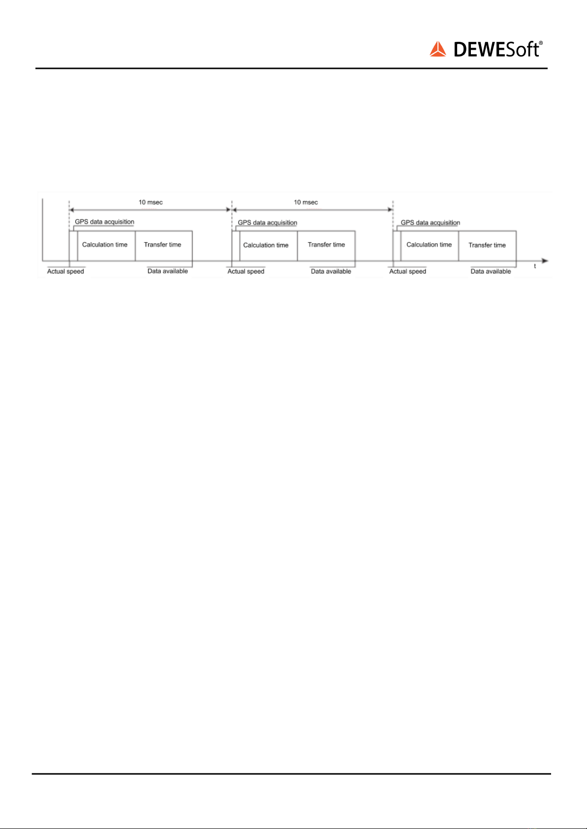
Beside the filter characteristic of the internal algorithm, the latency time on the serial interface is related
to the basic structure of any GPS-based sensor. After acquiring the GPS raw data, the time consuming
calculation to get the position and speed and the data transfer time will delay the data from the
DS-VGPS-HS.
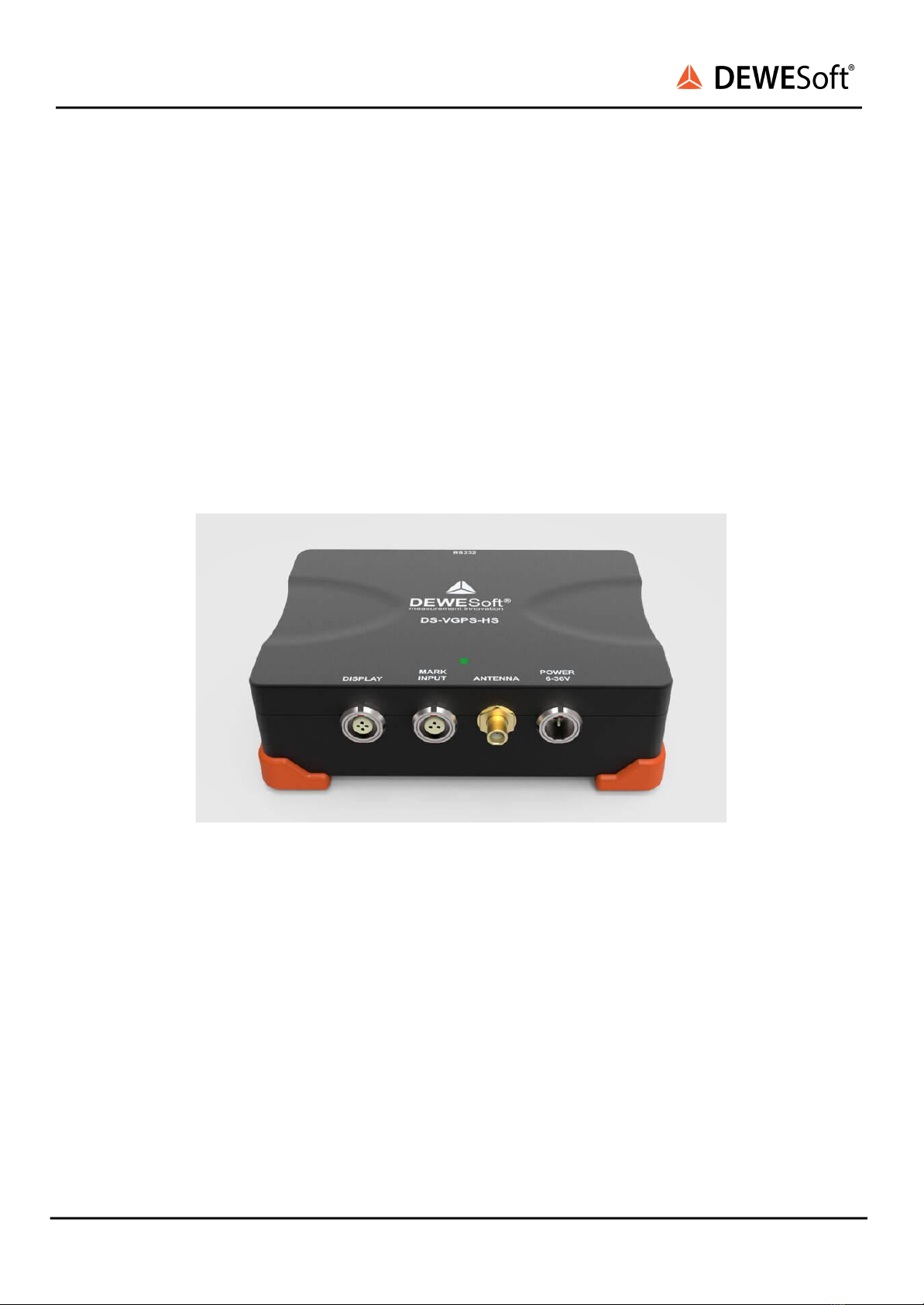
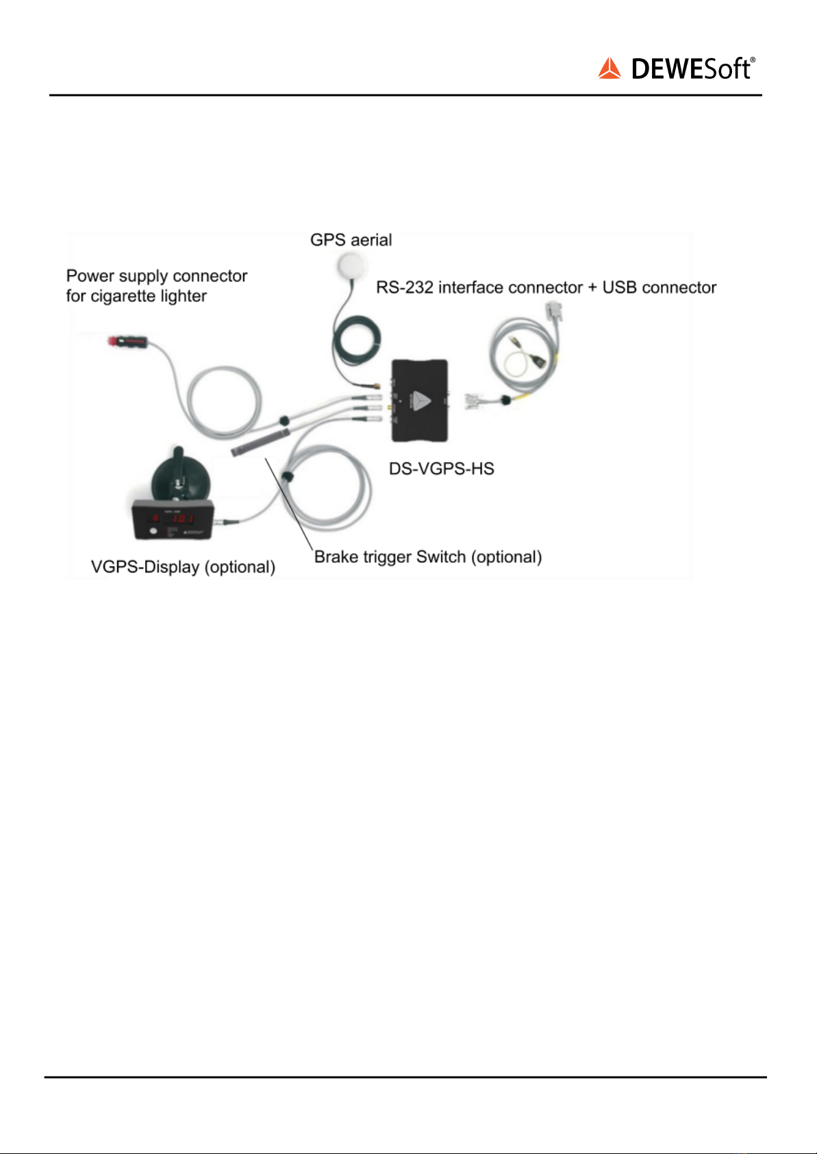
Image 2: Device overview
The time information is also included inside the data stream. By comparing the latency free PPS pulse
on the RS232 interface with the time information inside the data stream, the latency time is completely
eliminated.
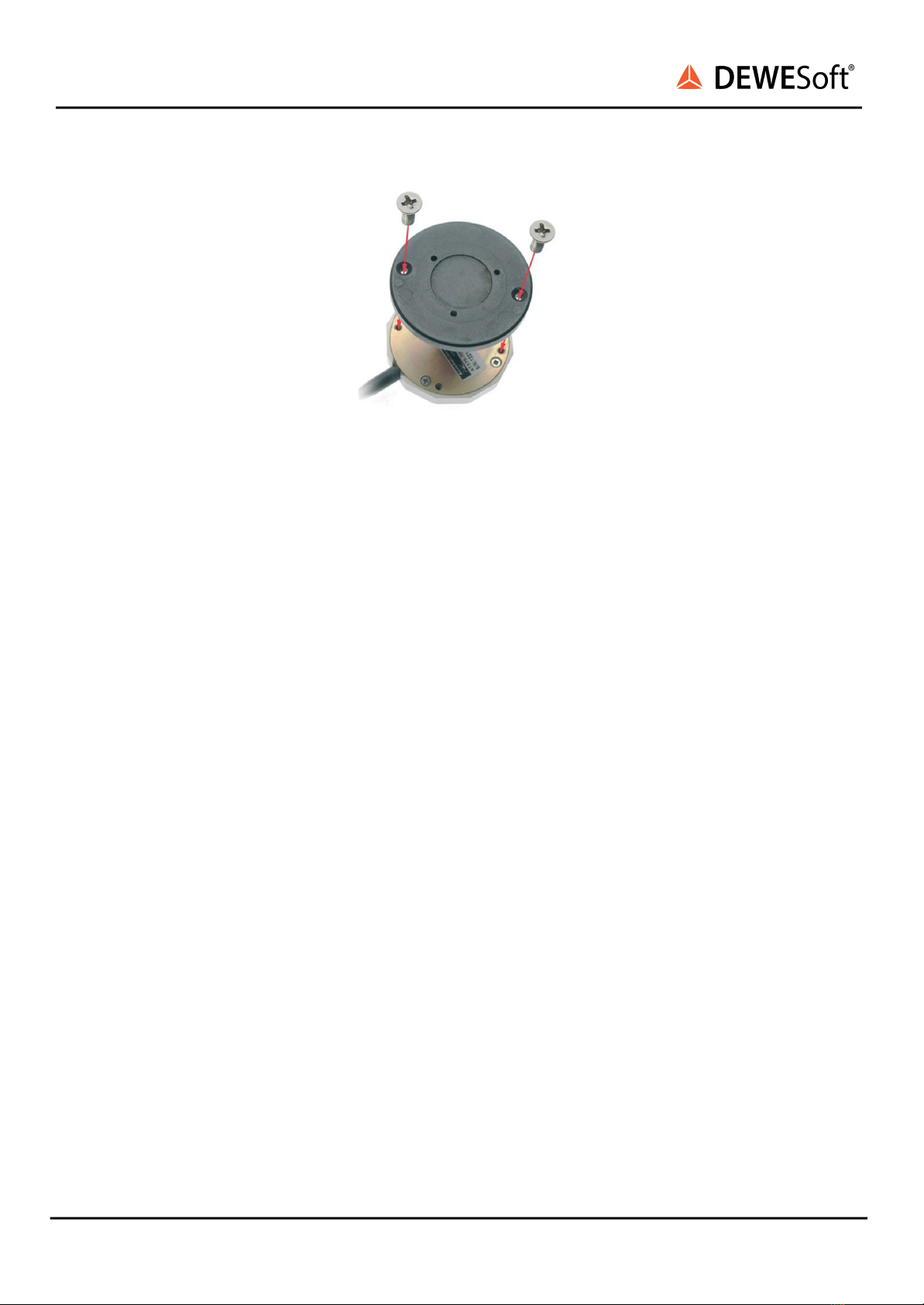
3.5. Mounting the aerial
The aerial supplied with the VGPS is designed to be mounted magnetically on top of the vehicle in a
horizontal plane. If the surface is not metallic, the aerial may be fixed by placing a piece of strong tape
over the top of the aerial. The positioning of the aerial is critical to the correct operation of the VGPS.
Note: For correct operation, the aerial requires a metallic subsurface with a minimal diameter of 15 cm.
This surface doesn’t have to be ferromagnetic.
The aerial picks up the signals from up to 12 satellites which are all in different places in the sky. These
satellites are not necessarily directly overhead, and can often be close to the horizon. Therefore it is best
to mount the aerial in a way that the least amount of metal obscures the view of the sky. On a domed
roof, place the aerial on the top of the dome. On an open car with a roll-over bar, place the aerial
horizontally on the highest point of the roll-over hoop and tape the wire securely to the frame. Although
the VGPS can work with at least three satellites, it's precision increases the more satellites it finds. If one
satellite disappears over the horizon, or behind an object, there are other satellites still in view.