DEWESOFT V21-1 Product manual

DS-VGPS-HSC
TECHNICAL REFERENCE MANUAL
DS-VGPS-HSC V21-1
1

DS-VGPS-HSC
TECHNICAL REFERENCE MANUAL
1. Table of contents
1. Table of contents 2
2. About this document 4
2.1. Legend 4
3. GPS based system for position, speed, and displacement measurement 5
3.1 Features 5
3.1.1 Speed sensor 5
3.1.2 Clock output 5
3.2. Specifications 5
3.3. Device overview 7
3.4. Functionality of the LEDs 8
3.4.1. Power (green) 8
3.4.2. Status (red) 8
3.5. Mounting the aerial 8
3.6. Warm-Up time 9
4. Scope of supply 10
5. Connection 11
5.1. Connector overview 11
5.1.1. Aerial connector 11
5.1.2. MULTI I/O connector (DSUB-9 female) 12
5.1.3. USB connector 12
5.1.4. VGPS – Display connector 13
5.1.5. Mark input connector 13
5.1.6. Power supply connector 13
5.1.7. Sync connector 14
5.1.8. Cable for external power supply 14
5.1.9. Cable for connecting VGPS to VGPS-Display (optional) 15
5.1.10. Cable for connecting VGPS to CAN 16
5.1.11. Output cable velocity and distance 17
5.2. Options 17
5.2.1. Brake trigger switch 17
5.2.2. Digital display 18
6. Installation of the DewesoftX® measurement software 20
6.1 Connecting the DS-VGPS-HSC to the DAQ-System 20
6.1.1. Synchronization to system with Clock and Trigger 20
6.2. Configuration of DewesoftX® for the DS-VGPS-HSC 20
6.2.1. Timing settings 23
6.3. Channel setup 25
6.4. Measurement 26
6.5. Analysis 27
V21-1 2/34

DS-VGPS-HSC
TECHNICAL REFERENCE MANUAL
7. Warranty information 28
7.1. Calibration 28
7.2. Support 28
7.3. Service/repair 28
7.4. Restricted Rights 28
7.5. Printing History 28
7.6. Copyright 29
7.7. Trademarks 29
8. Safety instructions 30
8.1. Safety symbols in the manual 30
8.2. General Safety Instructions 30
8.2.1. Environmental Considerations 30
8.2.2. Product End-of-Life Handling 30
8.2.3. System and Components Recycling 30
8.2.4. General safety and hazard warnings for all Dewesoft systems 31
9. Documentation version history 34
V21-1 3/34
DS-VGPS-HSC
TECHNICAL REFERENCE MANUAL
2. About this document
2.1. Legend
The following symbols and formats will be used throughout the document.
Important
It gives you important information about the subject.
Please read carefully!
Hint
It gives you a hint or provides additional information about a subject.
Example
Gives you an example of a specific subject.
V21-1 4/34
DS-VGPS-HSC
TECHNICAL REFERENCE MANUAL
3. GPS based system for position, speed, and
displacement measurement
3.1 Features
●Synchronized data acquisition combined with real time speed measurement
●Portable and rugged construction
●Insensitivity to road surface (can be used on mud offroad, water, snow, ice,..)
●Mark input for brake trigger switch
3.1.1 Speed sensor
●100 Hz update rate for speed and distance output
●Supports USB and CAN interface
●Supports differential GPS (SBAS) as standard function
●Online signal quality monitoring for standalone applications
●No calibration required
3.1.2 Clock output
●Output clock rate of up to 10 MHz
●One independent output frequency
●PPS accuracy of 100 ns
●Continuous synchronization to absolute GPS time
●Absolute long time stable
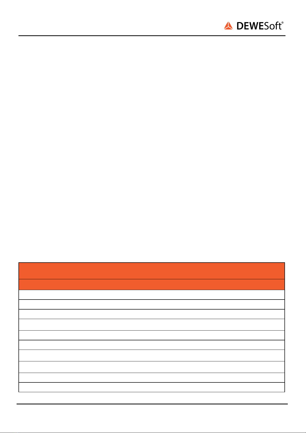
3.2. Specifications
V21-1 5/34
DS-VGPS-HS/HSC
NAVIGATION
Standalone (horizontal positioning)
1.2 m
Standalone (vertical positioning)
1.8 m
SBAS (horizontal positioning)
0.8 m (WAAS, EGNOS 0.3 m)
SBAS (vertical positioning)
1.2 m (WAAS, EGNOS 0.5 m)
Omnistar (horizontal positioning) *
-
Omnistar (vertical positioning) *
-
RTK (horizontal positioning) *
0.02 m
RTK (vertical positioning) *
0.02 m
Velocity accuracy
0.02 m/s
Roll & Pitch accuracy (dynamic)
-

DS-VGPS-HSC
TECHNICAL REFERENCE MANUAL
V21-1 6/34
Heading accuracy (dynamic with GNSS)
-
Slip angle accuracy
-
Range
Unlimited
Hot start time
< 10 s
Output data rate
20/100 Hz
GNSS
Supported navigation systems
GPS L1, L2* GLONASS L1, L2*
Supported SBAS systems
WAAS, EGNOS, MSAS, GAGAN, QZSS
ADDITIONAL FEATURES
PPS output
✓
IRIG B DC output
-
Dual antenna heading
-
RTK positioning
✓
HARDWARE
Interface
RS232 / USB, CAN, Analog, Digital
Operating voltage
9 to 36 V
Power consumption
250 mA @ 12 V
Operating temperatures
0 °C to 60 °C
Environmental protection
not IP rated
Input protection
Polarity & short overvoltage protection
Shock limit
MIL-STD 810 F
Dimensions
115 x 93 x 35 mm
Weight
740 g
INERTIAL SENSORS
Accelerometer
-
Gyroscope
-
Magnetometer
-
Pressure sensor
-
APPLICATIONS
Synchronisation and timing with DewesoftX®
DAQ
✓
Simple positioning
✓
Brake/Acceleration test
✓

DS-VGPS-HSC
TECHNICAL REFERENCE MANUAL
3.3. Device overview
The DS-VGPS-HSC offers a unique combination of a high dynamic GPS based speed sensor and a GPS
synchronized time base generator. This combination allows completely synchronized data acquisition of
multiple systems located inside and outside of moving vehicles.
The sensitivity of the analog speed and displacement output is free programmable. Due to the 100 Hz
update rate the latency time is as low as 9 ms. Using the unique PPS sync technology the latency time
of the digital interfaces (USB or CAN) are corrected online.
Image 1: VGPS HSC inputs and outputs
V21-1 7/34
Vehicle dynamics
-
Lane change
✓
Circle drive
✓
Chassis development
-
Advanced driver assistance systems testing
✓
Comfort testing
-
Pass by Noise
✓
FuSi
✓
Orientation of different object
-

DS-VGPS-HSC
TECHNICAL REFERENCE MANUAL
The base of any GPS receiver is precise time measurement. In addition to the position information a
precise PPS (pulse per second) is generated by the GPS engine. This pulse is used to synchronize 80
MHz oscillators with software PLL (phase locked loop). The result is an ultra stable 80 MHz clock source
which is completely free of drift over time.
The communication to the host is provided over CAN or standard USB interface.
3.4. Functionality of the LEDs
3.4.1. Power (green)
The power LED is solid green when the DS-VGPS-HSC is in normal operation.
3.4.2. Status (red)
3.5. Mounting the aerial
The aerial supplied with the VGPS is designed to be mounted magnetically on top of the vehicle in a
horizontal plane. If the surface is not metallic, the aerial may be fixed by placing a piece of strong tape
over the top of the aerial. The positioning of the aerial is critical to the correct operation of the VGPS.
Note: For correct operation, the aerial requires a metallic subsurface with a minimal diameter of 15 cm.
This surface doesn’t have to be ferromagnetic.
The aerial picks up the signals from up to 12 satellites which are all in different places in the sky. These
satellites are not necessarily directly overhead, and can often be close to the horizon. Therefore it is best
to mount the aerial in a way that the least amount of metal obscures the view of the sky. On a domed
roof, place the aerial on the top of the dome. On an open car with a roll-over bar, place the aerial
horizontally on the highest point of the roll-over hoop and tape the wire securely to the frame. Although
V21-1 8/34
The red status LED indicates current status of
device:
At normal operation - when DS-VGPS-HSC is
locked to the selected time source - it shortly
blinks once a second.
Image 2: LED Normal Operation
When the time source signal is missing (neither
GPS or IRIG time code signal), the device
automatically goes to flying-wheel operation. This
is indicated by inverted blinking.
Image 3: LED Missing Signal

DS-VGPS-HSC
TECHNICAL REFERENCE MANUAL
the VGPS can work with at least three satellites, it's precision increases the more satellites it finds. If one
satellite disappears over the horizon, or behind an object, there are other satellites still in view.
Image 4: GPS antenna
3.6. Warm-Up time
When the VGPS is used for the first time, has been moved more than 200 km or not used for 10 hours
(since last usage), it is recommended to perform a ‘cold start’. To get the best performance from your
VGPS in the future, perform this cold start in an open place with a good all round view to the sky. Allow
the VGPS to map the satellites for at least 20 to 30 minutes. The VGPS builds up the ‘Ephemeris’ data on
each satellite which is stored in a non-volatile memory, and means future satellite tracking is swift and
stable. Once the VGPS has carried out a successful cold start, future satellite lock from power up will
take between 15 seconds and 1 minute. Before going to test in a shady environment with tall objects or
near to trees, allow the VGPS to settle in an open space for 5 to 10 minutes.
V21-1 9/34
DS-VGPS-HSC
TECHNICAL REFERENCE MANUAL
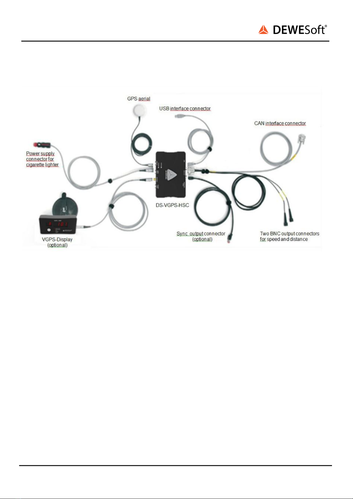
4. Scope of supply
Image 5: Connections
V21-1 10/34
Other manuals for V21-1
4
Table of contents
Other DEWESOFT Car Navigation System manuals


