DextraNet DHC-245 User manual

www.dextranet.com

www.dextranet.com
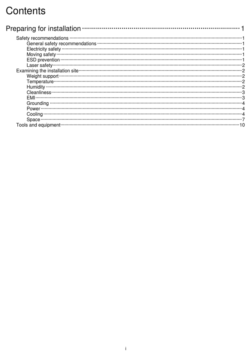
Contents
I. Overview of Dextranet PDSL5M
II. Features of Dextranet PDSL5M
III. Configuration and Specification
1. Network diagram
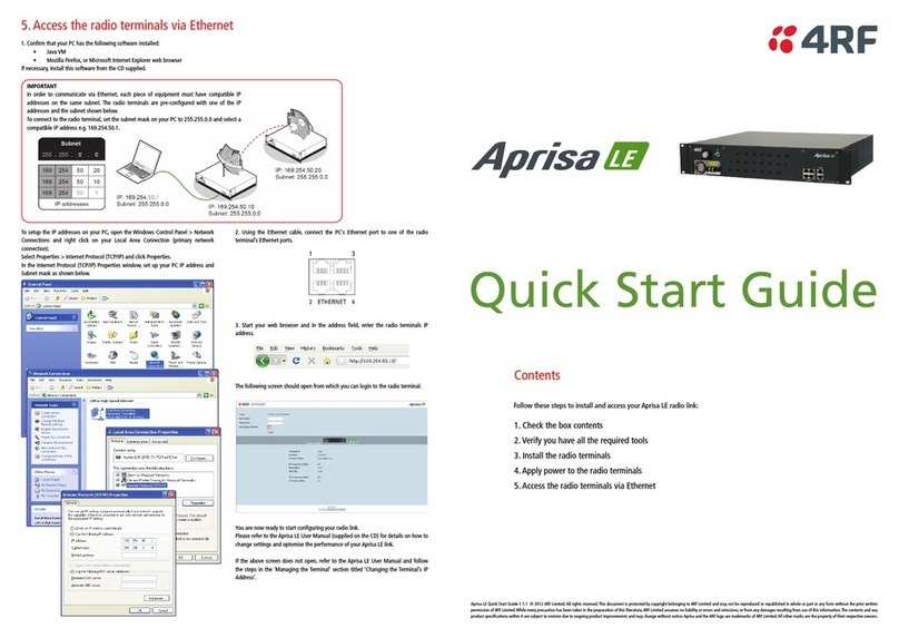
2. Configuration
3. Specification
IV. Installation Procedure
1. Preparation of installation
2. Wiring in MDF room
V. Bridged Environment
1. Definition of filters
2. How to use filters
3. Solution for bridged tabs
VI. Network management function
1. Overview
2. Features
3. How to run DHC-245 management function
4. How to access management function via serial interface
5. How to access management function via web browser

3
www.dextranet.com
I. Overview of Dextranet PDSL 5M
Dextranet PDSL5M is an Internet access equipment to transmit
IEEE802.3 Ethernet packet through 2 wire telephone lines, ensuring
the transmission speed of 5Mbps up to 500m. The equipment
incorporates multiple enhanced technologies such as 5Mbps data
modulation, CSMA/CA for half-duplex data transfer with 1 pair of
telephone lines and line interface technology.
Without wiring additional UTP cables, that is, only with the existing
telephone line, it allows you to enjoy speedy data transmission
(5Mbps) enough to send moving pictures beyond MPEG-2. As such, it
fully meets the requirements of service providers as well as
subscribers, providing a cost-effective way for high speed Internet
service.
Dextranet PDSL 5M includes DHC-245 (central concentration
equipment for 24 subscribers) and DHS-025W (subscriber modem
with two Ethernet interfaces for connecting subscriber PCs and set-top
box).

4
www.dextranet.com
II. Features of Dextranet PDSL 5M
• Port based V-LAN (Virtual LAN)
• IEEE 802.1q tagged V-LAN
• Access security: access control of management entity
Security
• Console port for system configuration and monitoring
• Web based system management interface
• SNMP: MIB-2, RMON supported
• Remote software upgrade by FTP
• RMON statistics: traffic statistics per subscriber
• MAC address limiting per subscriber
System
Management
Function
• Cost-effective solution for hotels and apartments
• Integrated with Ethernet switching function
Cost Effective
• Stable data transmission of 5Mbps up to 500m distance
• No speed degradation according to the distance
Stability
• Subscriber packet classification by V-LAN tagging
Billing function
• Half-duplex communication based on CSMA/CA (Carrier
Sense Multiple Access/Collision Avoidance)
• Both telephony and Internet service available through 1
pair of telephone line
• Data transmission bandwidth: 2~5MHz
• Frame format : IEEE 802.3
Transmission
Protocols

5
www.dextranet.com
III. Configuration and Specification
Telephone line
PBX
SUBSCRIBERMDF
Internet
Distance 500M
Distance 500M
Symmetric 5Mbps
Symmetric 5Mbps
DHC-245
100M Ethernet
Ethernet
100Base-T
DHS-025W
• Central Unit : DHC-245 (Concentrate 24 Subscribers)
• Subscriber Unit : DHS-025W
Distance: 500M
1. Network Diagram
Ethernet
100Base-T

6
www.dextranet.com
①
e
fg
Front View
cPower LED: Indicate power supply
dOPR LED: Not used
eSubscriber Port Link, ACT LED
• Link: Indicates link connectivity between DHC245 and DHS-025W
• ACT: Indicates data transmission(every frame transmission makes
ACT LED turned on 0.5 second )
fRS-232C Port: A serial port to set up the system configuration of
DHC-245 and monitoring the port status
• 57600 bps
• 8 data
• 1 stop bit
gUplink Port: 100Base-T Ethernet Interface
• Auto-negotiation of speed(10/100) & duplex(half/full)
• Link and ACT LED
2. Configuration
c
d

7
www.dextranet.com
Rear View
cPower dCO/PBX Line
(port 1~24)
eSubscriber Line
(port 1~24)
1
25
50 26
Port 1 CO Line
Port 2 CO Line
Port 3 CO Line
Port 4 CO Line
Port 5 CO Line
Port 6 CO Line
Port 7 CO Line
Port 8 CO Line
Port 23 CO Line
Port 24 CO Line
Port 1 Subscriber
Port 2 Subscriber
Port 3 Subscriber
Port 4 Subscriber
Port 5 Subscriber
Port 6 Subscriber
Port 7 Subscriber
Port 8 Subscriber
Port 23 Subscriber
Port 24 Subscriber
1
25
50 26
• Separate connectors for CO/PBX
(Central Office/PBX) line and
subscriber line
• Connector for CO line:
port 1 – pin 1-26 and 24 – pin 24-49,
NC-pin 25-50
• Connector for subscriber
same as that for CO line

8
www.dextranet.com
AC 110/220V, 60HzPower ON/OFF switch
Half-duplex5Mbps
Transmission
Speed
Limits direct layer 2 communication between
subscribers
Port based VLAN
IEEE 802.1q V-LAN
Selective access management
function
Security function
Supports RMON, MIB-2
SNMP, CLI, Web based
management
RFC1157, RFC1623
Network
Management
Support auto-negotiation
Control speed and duplex (10/100Mbps, Half/Full
duplex)
10/100Base-T X 1
Uplink Interface
4.5 Kg
Weight
width X length X height440 X 331 X 48 (mm)
Size
24 subscribers
Subscribers
CPEV (KS) 0.5 mmMax. 500m
Service Distance
Telephone and Internet service over 1 pair of line2 Wire per subscriber(CPEV cable)
Subscriber line
One for Central Office/PBX line , One for
Subscriber line
RJ-21(50-Pin) x 2
Rear
System controlRS-232C x 1 (Console interface)
100Base-T uplink portRJ-45 x 1(Ethernet interface)
Front
Inter
face
NoteSpecificationItem
3. Specification

9
www.dextranet.com
IV. Installation Procedure
1. Preparation for installation
Overall environmental information on the installation location, especially
based on the features of DHC-245 are required.
The information enables you to install the equipment in prompt and accurate
manner, and provides you with easy approach for after-sales service.
Listed below are the information required for environmental survey.
• In-house wiring diagram
• Types and features of subscriber line between MDF and subscriber
(category class and line thickness)
• Space for equipment installation and environmental elements
(ventilation, drainage and power etc.)
• If there is any spare line for subscribers

10
www.dextranet.com
•In-house wiring diagram:
Attenuation may be varied according to the in-house telephone line wiring.
Please check cascaded connections, bridged tabs, open terminations and
the number of telephones and make the diagram.
•Types and features of subscriber lines
(category class and thickness)
Features of subscriber lines determine the amount of signal loss and
interference between subscriber lines. CAT3/4/5 twisted pair cable is
generally recommended for lossless data communication.
However, untwisted cable(e.g., TIV and SH cable) which may result
excessive interference are not recommended. Also bridged tabs especially
with open end point may result severe signal loss.
Rm#4
Rm#3
Rm#1
Rm#2
An example of wiring diagram

11
www.dextranet.com
•Space for equipment installation and environmental
element (ventilation, drainage and power etc.)
It is required to understand the subscriber extension plan, ventilation and
drainage for the installation site. This is to ensure successful equipment
installation and endure the rainy season or hot temperatures. Be mindful
that dust may damage system components if they are installed in such
places.
•If there is any spare line
If there is any spare lines, it is strongly recommended to use spare lines for
subscriber connection. It can reduce the time and efforts to install the
system because it doesn’t require

12
www.dextranet.com
2. Wiring in MDF room
(1) Connecting Subscriber or CO line
(2) Connection to Internet
Connect the uplink port of DHC-245 to router or billing server.
CO/PBX Line Connector Subscriber Line Connector
cConnection to CO/PBX and subscriber line: Connect the line from the
telephone office/ PBX to the CO/PBX line connector, and connect the line
from the subscriber to the subscriber line connector in case of using
telephone line.
dConnection to subscriber line only: Connect the line from the subscriber
to the subscriber line connector in case of using spare line.
CROSSOVER
ETHERNET

13
www.dextranet.com
(3) Connecting numbers of DHC-245s
Connect the Ethernet cable between the Ethernet switch and the uplink port
of DHC-245. Uplink(or anyone) port of Ethernet switch should be connected
to gateway router or billing server.

14
www.dextranet.com
(4) Connecting telephone line
cIf there are any spare lines available
it is allowed to install the equipment by connecting the subscriber line to
DHC-245 subscriber connector if there are spare lines available. Spare
line can prevent the problems that may be caused when voice and data
is transferred over a pair of line simultaneously.
•• ••
CO
MDF
DHC-245
Spare line
Main line
Subscriber Line
Connector

15
www.dextranet.com
dIf there are no spare lines available
When the same line is used for both voice and data signals)
When a pair of telephone line is used for both voice and data signals,
cut the CO line connected to the line distribution panel and connect it to
pins 1 and 26 (incoming CO lines) of the DHC245. Then connect the
subscriber line pins on the line distribution panel to the subscriber line
connector.
1
26
25
50
(1,26)
DHC-245
1
25
2650
CO line
(1,26)
•• ••
Line
Distribution
Panel
X
Subscriber
line
cutting

16
www.dextranet.com
Every end point of communication line should be terminated properly to avoid
signal reflection. And filter should be used in a bridged tap environment to
minimize signal attenuation by blocking unnecessary signal flow to bridged line.
As shown in the above figure, if a line is added on the middle of
communication lines, the data signal flows on both lines. If the line end point is
not terminated properly, the data signal is reflected back from the end point
and makes collision at the bridged point, causing severe signal loss. In order to
solve this problem, a bridge filter should be used to block the reflected wave.
Telephone filter, bridge filter and terminal filter can be used to solve the
problems according to the bridged environment.
V. Bridged Environment
Un-terminated
bridge
Collision
Line
Distribution
Panel
Suggested wiring

17
www.dextranet.com
1. Definitions of filters
A terminal filter is installed at the end of the line, to
reduce reflection of data signal. The filter supports
the telephone filter functions, and reduces
reflected wave through impedance matching.
Terminal filter should be connected to the open
end point where no modem is connected to,
regardless of telephone connection.
A bridge filter is installed between main line and
bridged telephone line. The filter blocks the data
signal only and telephone signal flows the filter
without attenuation.
Terminal filter:
Bridge filter:
This filter is used to prevent data signal
attenuation caused by the telephone. It passes
voice signal only, and blocks data signal.
Telephone filter is used when connecting a
telephone in the middle of the line. Terminal filter
is used when connecting a telephone at the end of
the line.
This filter is not required when no telephone is
connected.
Telephone filter:

18
www.dextranet.com
•There are two telephone filters/terminators in it. The pin number 3 & 4 and
pin number 2 & 5 are used for each telephone.
•For utilization as the telephone filter, connect the line side of RJ-11
connector to the incoming line part (RJ-11 wall jack), and connect the
telephone to the telephone side of filter.
•For utilization as the terminal filter (connecting the filter to the open end
point of the telephone line), connect the line side of RJ-11 connector to the
incoming line part (RJ-11 wall jack), and enable termination function by the
strap inside of the filter.
2. How to use the filters
The included Telephone filter provides the functions of both the telephone filter
and the terminal filter. It would be possible to select the termination function
with the appropriate jumper on the PCB.
Line 1
Line 2
Phone 1
Phone 2
Line
side
Telephone
side

19
www.dextranet.com
3. Solution for bridged tabs
If any bridge tap is found during the installation, take corrective actions as
explained in the following slides.
1) Connecting the telephone at the middle point where the line is bridged:
Use the telephone filter.
2) Connecting the telephone at the end of the line:
Use the terminal filter to prevent reflected waves that may occur at the end of
the line.
Data signal
Telephone signal
Telephone filter DHS-025W
Terminal filter
DHS-025W
Data signal
Telephone signal

20
www.dextranet.com
3) If numbers of telephones are used on the in-house lines:
A bridge filter is recommended to prevent noise coming from the telephone line.
If there are less than 2 telephones to be connected, the telephone filters can be
used. However, if more telephones are connected, the bridge filter is strongly
recommended at the bridged point to prevent data signal attenuation.
4) If no device is installed at the end of bridged line
Use the terminal filter at the end of the line to prevent the reflected wave.
Terminal
filter
Telephone
filter
DHS-025W
Bridge filter
Data signal
Telephone signal
Terminal filter
DHS-025W
Data signal
Telephone signal
Table of contents


