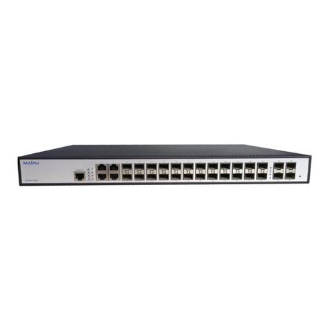
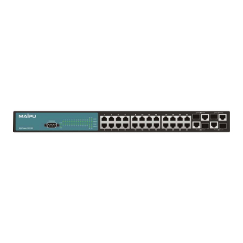
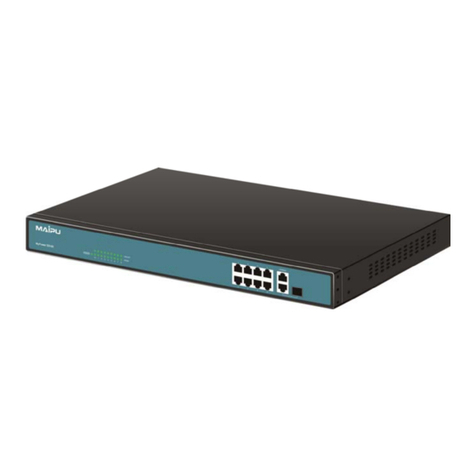
Maipu S2000-8/16 10/100Mbps Ethernet Switch User manual

2011 Maipu Communication Technology Co., Ltd, All Rights Reserved
MyPower S2000 Series Backward Power Feeding
Switch User Manual

2011 Maipu Communication Technology Co., Ltd, All Rights Reserved
2
This manual copyright belongs to Maipu Communication Technology Co., Ltd., without the written
permission of the copyright holder, any unit or individual shall not abstract, reproduce or translate in any
way.
Rights Reserved.
Scheme:
Research data services
* * *
Maipu Communication Technology Co., Ltd
No. 16, Jiuxing Avenue
Technical support hotline:400-886-8669
Fax: (+8628) 85148948
E-mail:support@mail.maipu.com
URL:http://www.maipu.com
Zip code:610041
Version: Edition v1.0 August 2011

2011 Maipu Communication Technology Co., Ltd, All Rights Reserved
3
Content
Chapter 1 Accessing Device .....................................................................7
1.1
Accessing Mode ....................................................................... 7
1.2
Web Configuration.................................................................... 7
1.3
Log in........................................................................................ 7
Chapter 2 Management ............................................................................9
2.1
Password Configuration ........................................................... 9
2.2
System Configuration ............................................................... 9
2.3
System Status ........................................................................ 10
2.4 Restore to Default Configuration .....................................................11
2.5
Firmware Update.....................................................................11
2.6
Reboot Device........................................................................ 12
Chapter 3 Port Configuration ..................................................................14
3.1
Port Configuration .................................................................. 14
3.2
Port Mirror .............................................................................. 15
3.3
Bandwidth Control .................................................................. 15
3.4
Broadcast Suppression .......................................................... 16
3.5
CpuCar and port enable configuration ................................... 16
Chapter 4 VLAN Configuration............................................................18
4.1
VLAN Mode ............................................................................ 18
4.2
VLAN Member........................................................................ 18
4.3
VLAN Fast Configuration ....................................................... 20
Chapter 5 Packet Accounting ..............................................................22
5.1
Packet Accounting.................................................................. 22
Chapter 6 Qos Configuration...............................................................23
6.1
Priority Mode .......................................................................... 23
6.2
Priority Configuration Based on TCP/UDP and IP TOS/DS... 24
6.3
802.1p and Physical Port Priority ........................................... 25
Chapter 7 Packet Security Filtering ....................................................26
7.1
MAC Address Binding ............................................................ 26
7.2
TCP/UDP Filtration................................................................. 26
Chapter 8 Spanning Tree......................................................................28
8.1
STP Bridge ............................................................................. 28
8.2
STP Port ................................................................................. 28
8.3
Loop Detection ....................................................................... 29
2011 Maipu Communication Technology Co., Ltd, All Rights Reserved
4
Chapter 9 Truck .....................................................................................31
9.1
Truck Configuration ................................................................ 31
Chapter 10 DHCP Relay Agent.............................................................32
10.1
DHCP Relay Agent................................................................. 32
10.2
Relay Server........................................................................... 32
10.3
VLAN MAP Relay Agent......................................................... 32
Chapter 11 Backup and Recovery Configuration..............................34
11.1 Configure Backup and Recovery .................................................. 34
Chapter 12 Other Function...................................................................35
12.1
Other functions ....................................................................... 35
Chapter 13 Overtime Exit and Re-log in .............................................36
13.1
Overtime Exit.......................................................................... 36
13.2
Re-log in ................................................................................ 36
Chapter 14 Restore to Default Hardware Configuration.........................37
14.1
Restore to Default Hardware Configuration ........................... 37
Appendix 2 Terms ................................................................................. 38
Appendix 2 Terms ................................................................................. 40
Appendix 3 Cable ................................................................................. 41
RJ-45 Connector ........................................................................... 41
Make Cable ................................................................................... 42

2011 Maipu Communication Technology Co., Ltd, All Rights Reserved
5
Preface
Introduction
This manual introduces series backward power feeding switch in details. This manual can
help users to understand our product and also guide users to install, configure, manage
and maintain it.
Audience
This manual is for the networking professional who has experience working with the
concepts and terminology of the Ethernet and local area networking and is also familiar
with the switch software features.
Conventions
1. General conventions
Convention Description
Black Headings are in black
Times New Roman Normal paragraphs are in Times New Roman
Arial Cautions and notes are in Ariel
2. Command conventions
Convention Description
Boldface The keywords of command lines are in boldface.
Italic Command arguments are in italic
[ ] Items (keywords or arguments) in square brackets [ ] are
optional
{X| Y|…} Alternative items are grouped in braces and separated by
vertical bars. One is selected.
[X| Y|…] Optional alternative items are grouped in square brackets
and separated by vertical bars. One or none is selected.
! A line starting with ! sign is comments.

2011 Maipu Communication Technology Co., Ltd, All Rights Reserved
6
3. Symbols
Symbol Caution Description
Note,
comment, tip, knowhow,
thought
A complementary description
Caution,
warning, danger
Reader must be extremely
careful during the operation
Technical assistance
The Maipu website provides online documents and tools for product and software
updating, manual revising, and technical serving etc.
URL:www.maipu.com
E-mail:support@mail.maipu.com
Service hotline:400-886-8669

2011 Maipu Communication Technology Co., Ltd, All Rights Reserved
7
Chapter 1 Accessing Device
1.1 Accessing Mode
Configure the device through WEB configuration page, including: switch management,
port configuration, and VLAN configuration. Use your web browser (Internet Explorer5.0
or later is recommended) to configure the switch.
1.2 Web Configuration
Each network interface supports WEB management, default administrative IP is
192.168.2.1, mask is 255.255.255.0 and default gateway is 192.168.2.254. PC of the
administrator should connect to the device for administration.
1.3 Log in
Type the IP address http://192.168.2.1 in the location box (PC of the administrator should
connect to the device for administration) and press enter:
Type username in (ID) and password in (Password) before click (OK). Then enter into
configuration page .
Note: Default username is admin and password is admin, which can be modified in
(Authentication Configuration).
The main page as below:

2011 Maipu Communication Technology Co., Ltd, All Rights Reserved
8
The left is index of each function options and right is the description of (
Advanced Features
)
and (
Basic Features
).

2011 Maipu Communication Technology Co., Ltd, All Rights Reserved
9
Chapter 2 Management
2.1 Password Configuration
Click (Authentication Configuration) under(Administrator) on the left
Modify current username and password on this page.
Click (Update) to affirm configuration. Successfully modification will show as following:
Click (Re-login) to login in again using new username and password.
Note: Username and password can only use numbers and letters.
2.2 System Configuration
Click (System IP Configuration) under (Administrator) on the left:

2011 Maipu Communication Technology Co., Ltd, All Rights Reserved
10
Modify (IP Address), (Subnet Mask), (Gateway) and (IP Configure) on this page. IP
address cannot be all 0, all F and multicast address. Click (Update) to affirm configuration
and it needs rebooting the device.
2.3 System Status
System status includes: (MAC Address), (Number of Ports), (Comment) and (System
Version) as following:
Input device name in (Comment) and click(Update) to modify it. Successfully modification
will show device name on the page.
Input password “setmac” in (Set MAC Address) and click(Confirm) to turn to following
pages:

2011 Maipu Communication Technology Co., Ltd, All Rights Reserved
11
Write MAC address in this place and read/write the configuration value of PHY, MAC,
EEPROM.
2.4 Restore to Default Configuration
Restoring to default configuration means to restore to factory status, not including IP
address, username, and password.
Click (Load Default Setting) under (Administrator) on the left to turn to following page.
Click (load). Reboot the device after modification.
Click (Reboot) to reboot device.
2.5 Firmware Update
It supports following update methods:
1. through web browse
Click (Firmware Update) under (Administrator) on the left to turn to following page:

2011 Maipu Communication Technology Co., Ltd, All Rights Reserved
12
Enter password and confirm (the password is the same as the login in password) and then
click (Update) to enter flash to erase the page. Following page will appear after that.
Click (Browse) to select update file before click (Update) to update. It will last about 40
seconds. After successfully update, it will turn to login page
2. through TFTP
After flash erasure, run tftp client in Microsoft command line. Suppose device IP address is
192.168.2.1. Type : c:\tftp -i 192.168.2.1 put filepath\filename.bin and then press enter as
following:
Re-log in the system after update.
Caution: Default update password is admin. If it shows error on the page or the
update period is too long, please re-log in according to the prompt. Make sure the power is on.
2.6Reboot Device
Click (Remote Device) under (Administrator) to turn to following page:

2011 Maipu Communication Technology Co., Ltd, All Rights Reserved
13
Click (Confirm) and reboot device.

2011 Maipu Communication Technology Co., Ltd, All Rights Reserved
14
Chapter 3 Port Configuration
3.1 Port Configuration
On this page, port configuration include: Auto-N-Way, Speed, Duplex,
802.3x/backpressure, Tx Capability and Addr. Learning
Select “configure port” in (Port Configuration) and choose corresponded ports, and then
click(Update) .
(port status) and(port configuration) :
(port status) means the true status of port link negotiation.
Through combination key shift+p can configure PoE Mode at ports, as below, options set
to enable to the electrical port, disable as normal port. PD (Powered device) port means
link up with POE power supply. Normal port means linkup with PoE power supply.
By default, port 1 as normal port from the beginning to end (no configuration) , other ports

2011 Maipu Communication Technology Co., Ltd, All Rights Reserved
15
are PD ports. Only port1 can supply power to hanging down PD (Output 10W power) .
3.2 Port Mirror
System provides port mirror, that is, copy the packets in specific or more ports to
monitoring port for packet analysis and monitor. As following picture, select monitor port in
(Dest Port) and monitored port in(Source Port) .(Monitored Packets) includes: disable,
Rx, Tx and Rx&Tx. Choose needed configuration and click(Update)
Caution: One-to-one port monitor is not supported.
3.3 Bandwidth Control
In this function, user can configure the max sending and receiving rate. The speed
granularity is: Low 32Kbps and High 512Kbps.
Formula: Max sending and receiving rate
=Rate control (0~255) x 32 kbps (low bandwidth)
=Rate control (0~255) x 512 kbps(high bandwidth)
Click (update) to update configuration. Click (LoadDefault) to restore to default
configuration. After that, the speed rate is connecting speed as following:

2011 Maipu Communication Technology Co., Ltd, All Rights Reserved
16
Note: If the connecting speed rate is smaller than the bandwidth control rate, the
connecting speed rate will be bandwidth control rate.
3.4 Broadcast Suppression
As following, select port in (Enable Port) and input 0-63 in threshold which means the max
broadcast number permitting in certain in the port. Port rate 10Mbps equals to 5000us
time unit, and port rate 100Mbps equals to 500us time unit time.
3.5 CpuCar and port enable configuration
CpuCar mainly use to set port about the number of packets per unit time on the CUP,
Enable means global open, selected port means enable CpuCar, rate by default 200pps,
range 150-300, Disable means global shutdown.
Enable port is switch, non-selected port will shutdown.

2011 Maipu Communication Technology Co., Ltd, All Rights Reserved
17

2011 Maipu Communication Technology Co., Ltd, All Rights Reserved
18
Chapter 4 VLAN Configuration
4.1 VLAN Mode
VLAN modes divide into Port Based VLAN and Tag Base VLAN. By default is Port Based
VLAN mode. As below figure:
Click (Change VLAN mode) to shift VLAN mode. On Tag Base VLAN mode page, user
can configure Tag attribution, including Tag, Unmodify and Untag as following:
Note: If the link partner is a network interface card, it probably cannot recognize the
VLAN tag. In this case, it is strongly recommended the network administrator to remove
the VLAN tag of the corresponding port.
4.2 VLAN Member
It can be divided according to VLAN mode:
1. Port Based VLAN member configuration

2011 Maipu Communication Technology Co., Ltd, All Rights Reserved
19
(Port) is uplink port configuration and (Dest PORT) is downlink port configuration.
(LoadDefault) is default configuration. For example: configure e0/1 to be uplink port and
e0/1~16 to be downlink port to make e0/1 transmit packet to e0/2~16 as following:
Click (LoadDefault) to restore to default value, that is, all (Port) contains all (Dest PORT) .
Note: Configured downlink port must contain uplink port, such as (Dest PORT) must
contain e0/1.
2. Tag Base VLAN member configuration
Divide 16 groups of VLAN (1-16) in Tag Base VLAN mode, which cannot delete and

2011 Maipu Communication Technology Co., Ltd, All Rights Reserved
20
create. We suggest user click (Read) to load corresponded VID of configured VLAN and
enter VID (1-4094). Select VLAN member in (Dest PORT) and enter pvid corresponded
VLAN Index No. in (PVID Index) and click (Update) .
When deleting VLAN, click (Delete) of the delete VLAN VID in the drop down menu.
When modifying VLAN, modify the VLAN ID in the drop down menu in front of (Delete) ,
When VLAN Member Port ticks or non-ticks VLAN member port, VID Source port ticks
or non-ticks VLAN selected port, click(Update) .
4.3 VLAN Fast Configuration
Port isolation settings are based on Port Based. (Choice port number) is for uplink port.
For example, uplink port chooses 01, port disable as 02, click (update) configure. Port 1
doesn’t transmit packets to port 2 after configuring, but can transmit to all downlink ports.
VLAN member as below:
Table of contents
Other Maipu Network Router manuals

Maipu
Maipu MP1800 Manual

Maipu
Maipu MP1800X-40 User manual

Maipu
Maipu SM3100-9TC-AC Manual

Maipu
Maipu SM3100-28TC-AC Manual

Maipu
Maipu MP2900-04-AC User manual

Maipu
Maipu MP2800 Series User manual

Maipu
Maipu MP2801 User manual

Maipu
Maipu MP2600C Series User manual

Maipu
Maipu MP7500 User manual

Maipu
Maipu SM3300-28FX User manual