DeZurik ANSI/AWWA C540 User manual


DeZURIK
Instruction and Operating Manual Page 2 © 2022 DeZURIK, Inc.
Instructions
These instructions are for use by personnel who are responsible for the installation, operation and
maintenance of DeZURIK valves, actuators or accessories.
Safety Messages
All safety messages in the instructions are identified by a general warning sign and the signal word CAUTION,
WARNING or DANGER. These messages indicate procedures to avoid injury or death.
Safety label(s) on the product indicate hazards that can cause injury or death. If a safety label becomes difficult
to see or read, or if a label has been removed, please contact DeZURIK for replacement label(s).
Personnel involved in the installation or maintenance of valves should be constantly alert to potential
emission of pipeline material and take appropriate safety precautions. Always wear suitable protection
when dealing with hazardous pipeline materials. Handle valves which have been removed from service
with suitable protection for any potential pipeline material in the valve.
Inspection
Your DeZURIK product has been packaged to provide protection during shipment; however, items can be
damaged in transport. Carefully inspect the unit for damage upon arrival and file a claim with the carrier if
damage is apparent.
Parts
Replaceable wear parts are listed on the assembly drawing. These parts can be stocked to minimize
downtime. Order parts from your local DeZURIK sales representative or directly from DeZURIK. When ordering
parts please provide the following information:
If the valve has a data plate: please include the 7-digit part number with either 4-digit revision number
(example: 9999999R000) or 8-digit serial number (example: S1900001) whichever is applicable. The
data plate will be attached to the valve assembly. Also, include the part name, the assembly drawing
number, the balloon number and the quantity stated on the assembly drawing.
If there isn't any data plate visible on the valve: please include valve model number, part name, and
item number from the assembly drawing. You may contact your local DeZURIK Representative to help
you identify your valve.
DeZURIK Service
DeZURIK service personnel are available to maintain and repair all DeZURIK products. DeZURIK also offers
customized training programs and consultation services. For more information, contact your local DeZURIK
sales representative or visit our website at DeZURIK.com.

DeZURIK
ANSI/AWWA C540 Pneumatic Cylinder for G-Series Actuators
D10295 Page 3 March 2017
Table of Contents
Description - - - - - - - - - - - - - - - - - - - - - - - - - - - - - - - - - - - - - - - - - - - - - - - - -
4
Supply - - - - - - - - - - - - - - - - - - - - - - - - - - - - - - - - - - - - - - - - - - - - - - - - - - - -
4
Required Tools - - - - - - - - - - - - - - - - - - - - - - - - - - - - - - - - - - - - - - - - - - - - - -
4
Lubrication - - - - - - - - - - - - - - - - - - - - - - - - - - - - - - - - - - - - - - - - - - - - - - - - -
4
Adjustment - - - - - - - - - - - - - - - - - - - - - - - - - - - - - - - - - - - - - - - - - - - - - - - - -
4
Disassembly - - - - - - - - - - - - - - - - - - - - - - - - - - - - - - - - - - - - - - - - - - - - - - - -
4
Reassembly - - - - - - - - - - - - - - - - - - - - - - - - - - - - - - - - - - - - - - - - - - - - - - - -
5
DeZURIK
ANSI/AWWA C540 Pneumatic Cylinder for G-Series Actuators
D10295 Page 4 March 2017
Description
The ANSI/AWWA C540 Hydraulic Cylinder for use with G-Series Actuators is intended for water
hydraulic service. This cylinder can be used with Pumpcheck accessories.
Supply
The maximum cylinder supply pressure is 150 psi.
Required Tools
The cylinder is assembled with SAE fasteners. Tools required for adjustment and disassembly include
a set of combination wrenches, a flat-tipped screwdriver and a small hammer.
This cylinder is a pressure vessel. Supply pressure must be disconnected from the
cylinder and the cylinder completely relieved of pressure before disassembling the
cylinder. Failure to release pressure may result in personal injury and/ or damage to
other equipment.
Lubrication
If the cylinder is disassembled, lubricate the cylinder wall, piston seal, sealing rings and ring grooves
using one of these lubricants.
Dow Corning Molykote No. 44 (recommended)
Shell Retinax AM (alternate)
Shell Lithall MDS (alternate)
Adjustment
The set screw in the end of the cylinder is used to limit the cylinder stroke.
1. Turn the set screw in the end of the cylinder counterclockwise about five turns.
2. Close the valve. See Valve Instructions to determine closed position.
3. Turn the set screw clockwise until you feel resistance as it contacts the piston rod.
4. Lock the set screw in place with the nut. Be sure the thread seal is positioned properly.
Disassembly
Follow the steps below to disassemble the cylinder.
Servicing the actuator while the pipeline is under pressure can cause personal
injury or equipment damage. Relieve pipeline pressure before servicing the
actuator.
Accidental operation of power actuator can cause personal injury or equipment
damage. Disconnect and lock out power to actuator before servicing.

DeZURIK
ANSI/AWWA C540 Pneumatic Cylinder for G-Series Actuators
March 2017 Page 5 D10295
Disassembly (continued)
1. Shut off the air supply to the cylinder.
2. Relieve pressure in the cylinder.
3. If the actuator is powered, disconnect and lock out the pneumatic, hydraulic, or electrical power
to prevent accidental operation of the actuator.
4. Disconnect the cylinder tubing.
5. Remove nuts and washers from the tie rods, and remove cylinder cap.
6. Rotate the cylinder tube while pulling it from the piston.
7. Remove the nut on the piston rod.
8. Remove the piston.
9. Remove extension cap from other end of gear box housing.
10. Remove nuts and spring washers from the rack rod.
11. Pull the piston rod, complete with rack rod, from the cylinder head.
12. Take out the four screws and separate the cylinder head from the actuator housing.
13. Remove the seal in the cylinder head.
Reassembly
1. Install the piston rod sealing ring and Teflon backing rings as shown in Figure 1.
Figure 1—Piston Rod Seal Placement
a. Clean the groove in the cylinder head and lubricate all the parts.
b. Insert the seal ring in the groove. Make sure the seal ring lies flat in the groove.
c. Insert the Teflon backing rings. The backing rings are cut with a bevel. Be sure the ends
match and do not overlap.

DeZURIK
ANSI/AWWA C540 Pneumatic Cylinder for G-Series Actuators
D10295 Page 6 March 2017
Reassembly (continued)
2. Attach the cylinder head to the actuator. See Figure 2.
Figure 2—Cylinder Parts Location
3. Carefully install the rack rod and piston rod.
4. Eccentric valves: Install the spacer, spring washers and nuts on the rack rod. See Table B for
spring washer arrangement.
All other valves: Install the jam nuts on the rack rod.
5. Eccentric valves: Tighten the nut until the spring washers are completely compressed, and
then back off until they return to their normal uncompressed shape.
All other valves: Tighten the first nut.
6. Tighten the second nut.
7. Install the extension cap.
8. Put the piston on the piston rod and install the nut.
9. Remove the piston seal and its O-ring. Clean the O-ring, seal and groove. Lubricate the O-ring
and seal and replace. Use new O-ring and seal if necessary.
10. Lubricate the cylinder tube.
11. Carefully slide the cylinder over the piston. The seal and the cylinder must be well lubricated.
12. On 6-inch and larger cylinders, remove one or two of the tie rods.

DeZURIK
ANSI/AWWA C540 Pneumatic Cylinder for G-Series Actuators
March 2017 Page 7 D10295
Reassembly (continued)
13. Start the tube at a 45-degree angle and rotate the tube onto the piston. See Figure 3.
Figure 3—Installing Cylinder Tube
14. Clean the O-ring groove in the cylinder cap.
15. Lubricate and install the O-ring in the cylinder cap. Use a new O-ring if necessary.
16. Assemble the cylinder cap, lock washers and nuts. Tighten the nuts on the tie rods to the torque
specified in Table A.
Table A: Tie Rod Nut Torques
Cylinder Size
Torque
(ft lbs)
(cm/kg)
(Nm)
4”
12
175
16
6” & 8”
16
225
22
10” &12”
20
275
27
17. If the actuator is a powered actuator, reconnect power to the actuator.
DeZURIK
ANSI/AWWA C540 Pneumatic Cylinder for G-Series Actuators
D10295 Page 8 March 2017
Reassembly (continued)
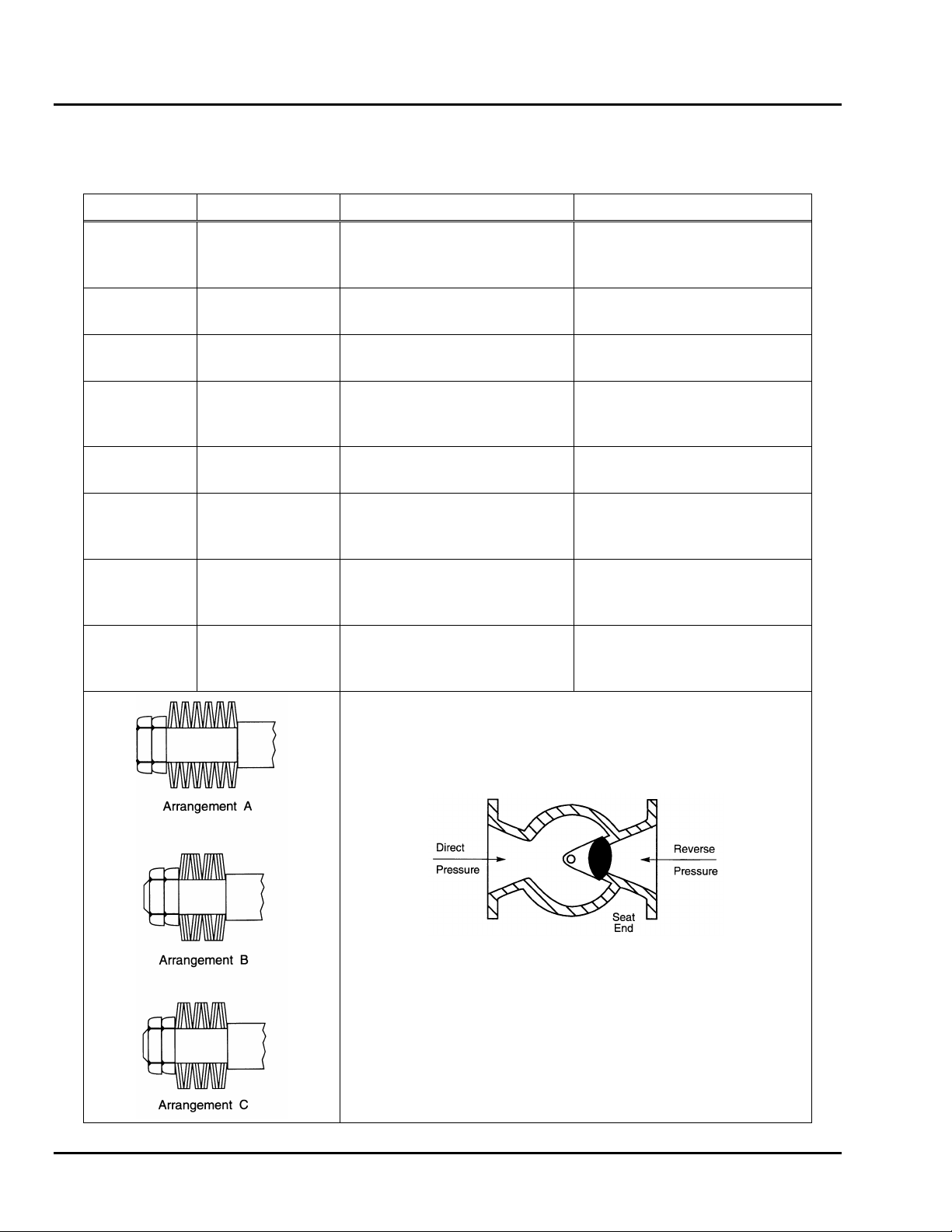
Table B: Rack Rod Spring Washer Arrangement
Valve Size
Actuator Size
Direct Pressure
Reverse Pressure
4
5
6
All
All
All
A
B
B
A
B
B
8
G6
G12
B
A
B
A
10
G6
G12
B
A
B
B
12
G6
G12
G16
B
B
A
B
B
A
14
G12
G16
B
A
B
A
16
18
20
All
All
All
B
B
B
B
B
B
24
G16-C8
G16-C10
G16-C12
B
B
B
C
B
C
30
G16-C8
G16-C10
G16-C12
C
B
B
C
B
C
Reverse Pressure: When the higher-pressure is at the seat end.
Direct Pressure: When the higher-pressure is opposite the seat.

Limited Warranty
DeZURIK, Inc. (“Seller”) manufactured products, auxiliaries and parts for a period of twenty-four (24) months from date of shipment from
Seller’s factory, are warranted to the original purchaser only against defective workmanship and material, but only if properly stored, installed,
operated, and serviced in accordance with Seller’s recommendations and instructions.
For items proven to be defective within the warranty period, your exclusive remedy under this limited warranty is repair or replacement of
the defective item, at Seller’s option, FCA Incoterms 2020 Seller’s facility with removal, transportation, and installation at your cost.
Products or parts manufactured by others but furnished by Seller are not covered by this limited warranty. Seller will provide repair or
replacement for other’s products or parts only to the extent provided in and honored by the original manufacturer’s warranty to Seller, in
each case subject to the limitations contained in the original manufacturer’s warranty.
No claim for transportation, labor, or special or consequential damages or any other loss, cost or damage is being provided in this limited
warranty. You shall be solely responsible for determining suitability for use and in no event shall Seller be liable in this respect.
This limited warranty does not warrant that any Seller product or part is resistant to corrosion, erosion, abrasion or other sources of failure,
nor does Seller warrant a minimum length of service.
Your failure to give written notice to us of any alleged defect under this warranty within twenty (20) days of its discovery, or attempts by
someone other than Seller or its authorized representatives to remedy the alleged defects therein, or failure to return product or parts for
repair or replacement as herein provided, or failure to store, install, or operate said products and parts according to the recommendations
and instructions furnished by Seller shall be a waiver by you of all rights under this limited warranty.
This limited warranty is voided by any misuse, modification, abuse or alteration of Seller’s product, accident, fire, flood or other Act of God,
or your failure to pay entire contract price when due.
The foregoing limited warranty shall be null and void if, after shipment from our factory, the item is modified in any way or a component of
another manufacturer, such as but not limited to, an actuator is attached to the item by anyone other than a Seller factory authorized service
personnel.
All orders accepted shall be deemed accepted subject to this limited warranty, which shall be exclusive of any other or previous Warranty,
and this shall be the only effective guarantee or warranty binding on Seller, despite anything to the contrary contained in the purchase order
or represented by any agent or employee of Seller in writing or otherwise, notwithstanding, including but not limited to implied warranties.
THE FOREGOING REPAIR AND REPLACEMENT LIMITED WARRANTY IS IN LIEU OF ALL OTHER WARRANTIES, OBLIGATIONS AND
LIABILITIES, INCLUDING ALL WARRANTIES OF FITNESS FOR A PARTICULAR PURPOSE OR OF MERCHANTABILITY OR
OTHERWISE, EXPRESSED OR IMPLIED IN FACT OR BY LAW, AND STATE SELLER’S ENTIRE AND EXCLUSIVE LIABILITY AND YOUR
EXCLUSIVE REMEDY FOR ANY CLAIM IN CONNECTION WITH THE SALE AND FURNISHING OF SERVICES, GOODS OR PARTS,
THEIR DESIGN, SUITABILITY FOR USE, INSTALLATION OR OPERATIONS.
Disclaimer
Metric fasteners should not be used with ASME Class 150/300 bolt holes and flange bolt patterns. If you use metric fasteners with ASME
Class 150/300 bolt holes and flange bolt patterns, it may lead to product failure, injury, and loss of life. DeZURIK Inc. disclaims all liability
associated with the use of metric fasteners with ASME Class 150/300 bolt holes and flange patterns, including but not limited to personal
injury, loss of life, loss of product, production time, equipment, property damage, lost profits, consequential damages of any kind and
environment damage and/or cleanup. Use of metric fasteners with ASME Class 150/300 bolt holes and flange bolt patterns is a misuse that
voids all warranties and contractual assurances. If you use metric fasteners with ASME Class 150/300 bolt holes and flange bolt patterns,
you do so at your sole risk and any liability associated with such use shall not be the responsibility of DeZURIK, Inc. In addition to the
foregoing, DeZURIK’s Manufacturer’s Conditions apply.
Limitation of Liability
IN NO EVENT SHALL SELLER BE LIABLE FOR ANY DIRECT, INDIRECT, SPECIAL, PUNITIVE, OR CONSEQUENTIAL DAMAGES
WHATSOEVER, AND SELLER’S LIABILITY, UNDER NO CIRCUMSTANCES, WILL EXCEED THE CONTRACT PRICE FOR THE GOODS
AND/OR SERVICES FOR WHICH LIABILITY IS CLAIMED. ANY ACTION FOR BREACH OF CONTRACT BY YOU, OTHER THAN RIGHTS
RESPECTING OUR LIMITED WARRANTY DESCRIBED ABOVE, MUST BE COMMENCED WITHIN 12 MONTHS AFTER THE DATE OF
SALE. Sales and Service
For information about our worldwide locations, approvals, certifications and local representative:
250 Riverside Ave. N., Sartell, MN 56377 ● Phone: 320-259-2000 ● Fax: 320-259-2227
DeZURIK, Inc. reserves the right to incorporate our latest design and material changes without notice or obligation.
Design features, materials of construction and dimensional data, as described in this manual, are provided for your information only
and should not be relied upon unless confirmed in writing by DeZURIK, Inc. Certified drawings are available upon request.
Printed in U.S.A.
October 2021
Other manuals for ANSI/AWWA C540
1
Table of contents


