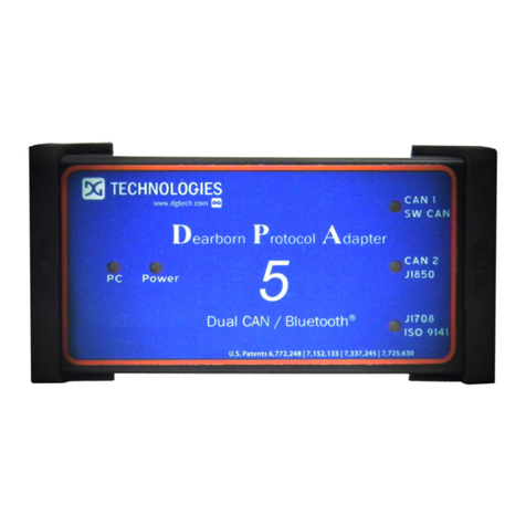
DG Technologies DPA XL User manual

Page | 2
The DPA XL has a very robust set of features, capabilities and functions including cybersecurity
enhancements by CyberTech from DG Technologies and is protected by CyberGuard inside. It is
also useful for vehicle ECU development, general design, hardware-in-the-loop simulation and
anywhere bi-directional communications with a vehicle network are required.
Permission is granted to copy any or all portions of this manual, provided that such copies are
for use with DPA XL product and that “© 2022 DG Technologies.”, (herein referred to as
“Dearborn Group”, “DG Technologies”, or “DG”), remains on all copies.
The accompanying software, provided for use with the DPA XL, is also copyrighted. Permission is
granted to copy this software for back-up purposes only.
I M P O R T A N T
To ensure your success with this product, it is essential that you read this document carefully
before using the hardware.
Damage caused by misuse of the hardware is not covered under product warranty. When using
this manual, please remember the following:
This manual may be changed, in whole or in part, without notice. DG assumes no responsibility
for any damage resulting from the use of this hardware or software. Specifications presented
herein are provided for illustration purposes only and may not accurately represent the latest
revisions of hardware, software or cabling. No license is granted, by implication or otherwise,
for any patents or other rights of DG or of any third party.
DG® logo is a registered trademark of DG Technologies, Inc. Other products that may be
referenced in this manual are trademarks of their respective manufacturers.

Page | 3
1Contents
1 Introduction............................................................................................5
1.1 Component Software Compatibility ................................................................................ 5
1.2 Standards and Protocols Supported ................................................................................ 6
1.3 DPA XL Hardware Specifications ...................................................................................... 6
1.4 System Requirements ...................................................................................................... 7
1.5 Power Connector.............................................................................................................. 7
1.5.1 Powering the Hardware............................................................................................ 7
1.5.2 Vehicle Network Connection .................................................................................... 7
1.6 DPA XL Configuration Utility ............................................................................................ 8
1.7 Setting Up Your Heavy-Duty OEM Diagnostic Applications............................................. 9
1.7.1 Compliant Application .............................................................................................. 9
1.7.2 General Setup for RP1210 OEM Application ............................................................ 9
1.7.3 Allison DOC.............................................................................................................. 10
1.7.4 Bendix ACom Diagnostics ....................................................................................... 10
1.7.5 Caterpillar Electronic Technician (CAT ET).............................................................. 10
1.7.6 Cummins INSITE...................................................................................................... 11
1.7.7 Detroit Diesel Diagnostic Link/Diagnostic Link ....................................................... 11
1.7.8 Dana Diagnostic Tool .............................................................................................. 12
1.7.9 DDEC Reports.......................................................................................................... 12
1.7.10 Eaton ServiceRanger ............................................................................................... 12
1.7.11 Freightliner ServiceLink........................................................................................... 13
1.7.12 Meritor-WABCO Toolbox........................................................................................ 13
1.7.13 Volvo/Mack Software ............................................................................................. 13
1.7.14 Navistar/International Software............................................................................. 15
1.8 General Setup for J2534 OEM Application..................................................................... 17
2Hardware Details...............................................................................18
2.1 DB-25.............................................................................................................................. 18
2.2 Auxiliary Power .............................................................................................................. 18
2.3 USB ................................................................................................................................. 18
2.4 12V DC............................................................................................................................ 18
2.5 Status Indicators............................................................................................................. 18

Page | 4
3Software Download and Installation................................................20
3.1 Software Requirements ................................................................................................. 20
3.2 Installing the DPA XL Software....................................................................................... 20
4Hardware Connection to the PC.......................................................23
4.1 Connect Cables to Tool .................................................................................................. 24
4.2 Connect Tool to Computer............................................................................................. 24
4.3 Connect Tool to Vehicle ................................................................................................. 24
4.4 Power Warning............................................................................................................... 24
5Included Software Applications.......................................................24
5.1 DG Update...................................................................................................................... 24
5.1.1 DG Update –Internet Connection Required .......................................................... 25
5.1.2 DG Update –Main Update Screen.......................................................................... 25
5.1.3 Successful Connect –Update Available.................................................................. 26
5.1.4 Advanced Settings–Setting Default Time Check for Updates................................. 26
5.2 AVT Software.................................................................................................................. 27
5.2.1 AVT Startup............................................................................................................. 27
5.2.2 AVT MD/HD Application ......................................................................................... 29
5.3 DPA XL Firmware Update............................................................................................... 34
5.3.1 Launch the DPA XL Firmware Update Programs Manually .................................... 34
Appendix A. Technical Support and Return Merchandise.................35
Appendix B. Warranty Information and Limitation Statements.........36
Appendix C. FCC and Certification Industry Canada.........................37
Appendix D. List of Acronyms Used in Document.............................39

Page | 5
1 Introduction
How it works: The DPA XL is used to connect vehicle networks to personal computers (PCs).
This allows programs written for the PC to retrieve pertinent information such as fault codes,
component information, as well as perform bi-directional communications for component level
diagnostics, tests, and component reprogramming.
The DPA XL communicates with the PC using either a USB cable or via Bluetooth (Class I or Class
II), and comes standard with the latest Technology and Maintenance Council (TMC)
Recommended Practice (RP) RP1210-compliant drivers, as well as Society of Automotive
Engineers (SAE) J2534-compliant drivers.
1.1 Component Software Compatibility
The adapter you have purchased is provided with the latest Technology and Maintenance
Council (TMC) RP1210/SAE J2534 compliant interface and has been tested with the following
OEM and component applications:
❑Allison DOC™
❑Bendix® ACOM
❑Caterpillar® Electronic Technician
❑Cummins® Insite™
❑Cummins PowerSpec
❑Dana Diagnostic Tool™
❑Detroit Diesel Diagnostic Link™
❑Detroit Diesel Reprogramming
Station™
❑Eaton ServiceRanger
❑Freightliner ServiceLink
❑GM GDS2
❑International® InTune
❑International® Master Diagnostics
❑International® NETS
❑International® Auto Upgrade (AU)
❑Isuzu IDSS II
❑Volvo Mack VCADS/PTT
❑Meritor-WABCO Toolbox
❑Navistar® Diamond Logic Builder
❑Navistar® HeRo
❑Navistar® NavKal
❑Navistar® NED
❑Navistar® ServiceMaxx
❑Paccar® Davie4
❑Vansco VMMS
❑ZF-Meritor TransSoft
Any application claiming RP1210/J2534 compliance should work if the application and
adapter both support the same protocol(s) and operating system(s).

Page | 6
1.2 Standards and Protocols Supported
The adapter you have purchased provides more protocol and standards support than any other
commercially available diagnostic adapter.
❑TMC RP1210 API
❑SAE J2534 API
❑SAE J1939
❑Single Wire CAN
❑Dual Wire CAN
❑CAN (ISO11898)
❑ISO15765
❑FT CAN
❑CAN FD
❑IESCAN - CAN@500k/J2284/GMLAN
❑SAE J1708
❑J1850 VPW (GM Class II)
❑J1850 PWM
❑ISO9141
❑ISO9141-2
❑ISO14230
❑GMLAN (HSCAN, SWCAN)
❑GMUART (SAE J2740)
1.3 DPA XL Hardware Specifications
Feature
Data
Dimensions
6.625 x 4.375 x 1.312 inches
Voltage Requirements
9 –32 Volts DC
Current Requirements
250mA maximum through voltage range
Operating Temperature Range
-40 to +85C
Wired PC Communications Type
USB Version 1.1 or Higher
Wired Connection
USB Cable (up to 15 feet)
Wireless Connection
Bluetooth (DPA XL is equipped with Class 1 radio)
Vehicle-Side Connector
DB25 Female
PC-Side Connector
Standard B-Type USB Jack
Auxiliary Power Jack
12 Volt DC
PC Device Drivers
TMC RP1210 Compliant Driver
SAE J2534 and SAE J2534-2 Passthru Drivers

Page | 7
1.4 System Requirements
We recommend a computer compatible with the latest version of the TMC RP1208 (PC
Selection Guidelines for Service Tool Applications).
Item
Requirement
PC
IBM-Compatible
Processor
1GHz or Faster
RAM
4GB
USB Port
USB Version 1.1 or Higher
Operating
System
Windows 10 & 11 (32-bit or
64-bit)
1.5 Power Connector
TheDPA XL has 3 possible sources of power:
oPower jack (12V DC)
oDB-25 connector powered by vehicle. Vehicle cable 9 PIN Deutsch Cable (P/N DG-295-10811) or 16
PIN J1962 OBDII Cable (P/N 295-DGT-1000717) cable attached to the vehicle
oUSB connection to host PC
There are limited uses for the 12V DC power jack. It may be used for the following:
oBenchtop programming
oUsage with a SAE J1939 Breakout box
WARNING
The DPA XL should NOT be powered via the 12V DC power jack and DB-25
(Deutsch or OBD-II cable) simultaneously.
Connecting to multiple power sources may cause damage to the hardware.
1.5.1 Powering the Hardware
Once a power source has been connected, the POWER LED should light green. Depending on the
vehicle, the key may need to be turned to turn the key to the on position before data link
traffic and / or power is supplied through the diagnostic connector.
1.5.2 Vehicle Network Connection
The vehicle network connection can be made by using the supplied vehicle cable or by a custom
cable to the hardware’s DB-25 (female) connector.

Page | 8
1.6 DPA XL Configuration Utility
The DPA XL tool comes with support for many protocols (see Standards and Protocols
Supported). The DPA XL Configuration Utility will tell you what protocols, API versions, and
Product Version are supported. You can also use the DPA XL Configuration Utility to get the
current firmware version. Utility can be found in:
Start ➔DGTech DPA XL ➔DPA XL Config Utility
Figure 1 DPA XL Configuration Utility
A Logging Configuration box will be listed with a number of selections. Select the Logging Type
and Logging Method you are going to use. Then select the OK button to confirm the selection.
Figure 2 DPA XL Configuration Utility –Select Logging Configuration

Page | 9
1.7 Setting Up Your Heavy-Duty OEM Diagnostic Applications
1.7.1 Compliant Application
The DPA XL works with all RP1210 compliant applications that support SAE J1708/J1587,
CAN/SAE J1939/ISO15765, SAE J1850 VPW (GM Class II), ISO9141, ISO14230, SWCAN, FTCAN
and SAE J1850 PWM protocols along with many others. This section shows how to configure
the most common RP1210-compliant diagnostic applications to work with the DPA XL.
1.7.2 General Setup for RP1210 OEM Application
The following examples show how to select the DPA XL tool you will be using. Selecting an
RP1210 adapter, commonly referred to as a Vehicle Datalink Adapter (VDA) varies widely from
different OEM applications; however, the terminology remains similar. The following table
helps to introduce you to the terminology and helps you to make the correct selections the first
time.
You must set up every application (in their own individual way) to use the DPA XL.
Not all OEM applications save the adapter configuration. Some applications make the
user select the adapter to be used every time the application is opened.
If You See These Terms
Select This
Vendor
API
DLL
Manufacturer
Adapter Manufacturer
DG Technologies DPA XL
DGDPAXL
Device Name
Adapter Name
The description of the tool can vary widely depending upon what part of
the vendor ini file that the application is displaying. In general look for
the tool name “DPA XL” that you will be using followed by the
connection type you plan on using.
•DPA XL, USB
Device Number
DeviceID
1 = DPA XL
Protocol
(Depends on Application)
Most Commonly Encountered:
•SAE J1708 (SAE J1708/SAE J1587)
•SAE J1939
•ISO15765
•CAN

Page | 10
1.7.3 Allison DOC
NOTE: Steps are for version 2020.1.0 (Build 08/21/2020); other versions vary slightly.
1. Start program
2. Click F4 - Connect
3. Select the Correct Transmission Type
4. Uncheck Smart Connect
5. Click Connect
6. Set Translator Device to DPA5 Multi-Application, USB
7. Select protocol of SAE J1939, CAN, SAE J1708 or SAE J1850
8. Click Advanced Setup
9. Select Vendor of DGDPAXL
10. Select Protocol of SAE J1939, CAN, SAE J1708 or SAE J1850
11. Select Devise Name of DPA XL
12. Device may be grayed-out on some selections
13. Select Channel of Auto, 1, 2, 3, or 4. Channel may not appear with some selections
14. Click OK
1.7.4 Bendix ACom Diagnostics
NOTE: Steps are for version 6.16; other versions vary slightly.
1. Start program
2. In Starter for ACom Diagnostics 6.16 window, click on PC/check mark/Truck icon located
bottom, middle-right
3. In Communications devise settings window [RP1210 tab] Available hardware interfaces
–select DPA XL (DPA XL)
4. Select green circle with check mark
5. Highlight ECU (if known) and select Start with ECU
6. If ECU not known, select Detect ECU
7. Follow on-screen instructions
1.7.5 Caterpillar Electronic Technician (CAT ET)
1. Start Program
2. Click Utilities ➔Preferences ➔Modify from the menu bar
3. Click on Communications tab (it could already be selected)
4. Select RP1210 Compliant Device
5. Click Advanced
6. Select Device Name
7. Click OK
8. Check Enable Dual Data Link Service
9. Click OK

Page | 11
Additional CAT ET Configuration Notes:
a. Enable Dual Data Link. This checkbox should be checked in most cases. However,
on some older SAE J1708 (ATA) only vehicles, ET will not work with this checkbox
checked. If ET does not connect, try un-checking, or checking this button.
b. The DPA product line does not support the CAT Data Link (CDL) protocol that is still
common among certain CAT off-highway vehicles and industrial stationary
equipment. CDL is a proprietary protocol and there are no generic adapters on the
market that support this protocol.
oTo find out if your vehicle/equipment is CDL or a standard protocol (SAE
J1708/ATA, SAE J1939), you should look at the diagnostic connector for that
equipment in the service manual.
1.7.6 Cummins INSITE
NOTE: Steps are for version 8.6.196 / DP; other versions vary slightly.
PowerSpec Version 5.5 or newer is required to use the DPA XL. Older versions of PowerSpec
were not completely RP1210-compliant.
1. Start Program
2. Locate text box bottom, middle, click on down arrow
3. Click on Add New…
4. Click Next | RP1210 Adapters (Next)
5. Select Vendor:
a. DG Technologies DPA XL
6. Select Adapter
a. DPA XL
7. Select Protocol:
a. Auto Detect (or choose protocol for your engine)
8. Click Datalink Adapter Connection Test (must be connected to data link), verify
successful connection.
9. Click OK | Next | Next | Save selection
1.7.7 Detroit Diesel Diagnostic Link/Diagnostic Link
NOTE: Steps are for version 8.12SP2; other versions vary slightly.
There are several ways to select the adapter:
1.7.7.1 From Inside DDDL
1. From Desktop click on SID Configure icon
2. Highlight DPA XL
3. Select OK

Page | 12
1.7.7.2 Desktop Detroit Diesel Electronic Tool Suite
1. Select Detroit Diesel Electronic Tool Suite icon from desktop.
2. Select Configure
3. Select DG DPA XL, select OK button
4. Select Refresh
5. Click on highlighted DDDL 7 or DDDL 6 item
1.7.7.3 Diagnostic Link (version 6.50) Icon on Your Desktop
1. Select Diagnostic Link icon from desktop
2. Select Look at active and inactive faults
3. To change the adapter, select Tools | Options | Interface
4. Select Device Name from Local Communication Interface drop-down list.
5. Select OK
1.7.8 Dana Diagnostic Tool
1. Start program
2. Under Adapter Selection, choose DG Technologies DPA XL: DPA XL
3. Select Connect J1708 or Connect J1939 or Connect PLC as appropriate for your
controller
1.7.9 DDEC Reports
1. Start program
2. Select Tools | Set Connection interface | DPA XL
3. Select OK
1.7.10 Eaton ServiceRanger
1. Start Program
2. Click Go To tab
3. Select Settings
4. Under Communication Adapter choose DPA XL
5. Under J1587 Connection choose DG DPA XL USB; Protocol=J1708; Speed=9600
6. Under J1939 Connection choose DG DPA XL USB; Protocol=J1939; Channel=1;
Speed=Auto
7. If connecting via Bluetooth, Select the DG DPA XL # [Bluetooth ID] Bluetooth) for both
the SAE J1708 and SAE J1939 device.
8. Click Apply

Page | 13
1.7.11 Freightliner ServiceLink
NOTE: Including Cascadia Model –Dual CAN Channels Start program
1. From the top menu bar, choose Admin
2. Click on Show All Devices.
3. Vendor = DG Technologies DPA XL
4. J1708 Device = Select Device Name
5. J1939 Device = Select Device Name
6. CAN Device
7. Click Configure
8. Select Device Name
9. Click Save Settings
1.7.12 Meritor-WABCO Toolbox
1. Start Program
2. Select Utilities
3. Select Adapter Selection
4. Select Vendor: DG Technologies DPA XL
5. Select Protocol: J1939 or J1708
6. Select Adapter: DPA XL
7. Select OK, then select X (top right) to close the Utilities Menu
8. Select Toolbox
9. Click System Setup; then select Adapter Selection
10. Verify selections are correct, select OK
11. Click on the Truck icon to start communication
1.7.13 Volvo/Mack Software
1.7.13.1 Volvo/Mack Premium Tech Tool (PPT) –Ver 2.X
1. Start Program
2. Select Settings from the PTT menu
3. Go to the Communication Unit tab:
4. Highlight DG Technologies DPA XL Application USB or DG Technologies DPA XL USB.
5. Verify radio button in default column is selected
6. Select Configuration…
7. Click on Advanced Settings, then select the down arrow on the right side of the text box
8. Highlight and click selection
9. Select the OK button
10. Verify DG DPA XL (SA) USB (or (MA) USB) is listed underneath Device Description:
11. Select the OK button
•Wait a few minutes to establish connection. If connection doesn't occur, re-boot the
PC.
•Do not select Connect immediately after PTT opens. Reading product data.... will
appear after a little bit of time while the connection is being established.

Page | 14
1.7.13.2 Volvo/Mack Premium Tech Tool (PPT) –Ver 1.X
1. Start Program
2. Select Settings from the PTT menu
3. Go to the Communication Unit configuration tab:
•It is here that you select the settings for each adapter that you may use. For
example, if you have an RP1210A adapter, it is here that you select which adapter,
port, and protocol.
•NOTE: This identifies the settings for each adapter. It does not select which adapter
the PTT application will use to communicate with the vehicle.
4. Go to the Comm unit selection tab:
•It is here that you identify which adapter is to be used by the PTT application to
communicate with the vehicle. You may have to change this selection depending
upon the vehicle.
•For example, if you typically use an 88890020 adapter in direct mode, when you
need to communicate with an older vehicle you will need to change to RP1210A
adapter or the 9998555 adapters, depending upon the vehicle.
1.7.13.3 Volvo/Mack VCADS –From Initial VCADS Setup
1. When prompted to configure a Communication Unit select RP1210A adapter
2. When prompted for the adapter, select Device Name
3. Select USB for the Port
4. Select J1708 for the protocol
5. When prompted for the Electrical Systems
a. Click Volvo Trucks –VERSION2 and select RP1210A Adapter
b. Click Volvo Trucks –Vehicle electronics ‘98 and select RP1210A Adapter
c. Click Mack Trucks –V-MAC I/II/III, ITC and select RP1210A Adapter
d. Click Volvo Trucks –V-MAC IV and select RP1210A Adapter
6. Continue with installation
1.7.13.4 Volvo/Mack VCADS –From Inside VCADS
1. Start Program
2. Click the Tools menu and choose Options
3. Select the Comm. Unit Configuration tab
4. Select RP1210A Adapter and then select Device Name
5. Select the correct Port (USB or Bluetooth)
6. Select J1708 for the protocol
7. Go to the Comm. Unit Selection tab:
a. Click Volvo Trucks –VERSION2 and select RP1210A Adapter
b. Click Volvo Trucks –Vehicle electronics ‘98 and select RP1210A Adapter
c. Click Mack Trucks –V-MAC I/II/III, ITC and select RP1210A Adapter
d. Click Volvo Trucks –V-MAC IV and select RP1210A Adapter
8. Click OK

Page | 15
1.7.14 Navistar/International Software
1.7.14.1 International Truck and Engine –Master Diagnostics
1. Start program
2. Choose File ➔MD Settings➔COM Device ➔Window with general VDA selection
3. Select Dearborn Group DPA XL ➔Window with specific port select your tools Device
Name.
1.7.14.2 Navistar Hydraulic ABS
1. Start program
2. Choose File ➔Hydraulic ABS Settings ➔COM Device ➔Window with general VDA
selection
3. Select Dearborn Group DPA XL ➔Window with specific port select your tools Device
Name
1.7.14.3 Navistar IPC
1. Start program
2. Choose File ➔Settings ➔COM Device ➔Window with general VDA selection
3. Select Dearborn Group DPA XL ➔Window with specific port select your tools Device
Name
1.7.14.4 Service Assistant
1. Start program
2. Press third button from the top along the left side (has an icon that looks like a
miniature interface cable)
a. A window comes up that says Communication Device Selection and has two drop
down boxes
b. Select Dearborn Group DPA XL ➔Select your tools Device Name
1.7.14.5 Navistar Diamond Logic Builder (DLB)
1. Select Diamond Logic Builder icon from desktop
2. Enter username/password; select OK
3. Choose Tools➔Select Com Link ➔Listing of adapters
4. Select DG Technologies DPA XL ➔DPA XL ➔SAE J1939 protocol
5. Choose Tools ➔Active Com Link or select F6

Page | 16
1.7.14.6 Navistar NavKal
1. Select NavKal icon from desktop
2. Enter username and password (if required)
3. Select Connection ➔Select COM Link ➔DG Technologies DPA XL ➔DPA XL ➔select
J1708 or J1939 depending on engine type
4. "Searching for Engine" appears
5. Select engine type when prompted and click OK button
1.7.14.7 Navistar HeRo
1. Select HeRo icon from the desktop
2. Enter username and password (if required)
3. Select Connection ➔Select COM Link ➔DG Technologies DPA XL ➔DPA XL ➔select
J1708 or J1939 depending on engine type
4. Select Connect & Scan button
1.7.14.8 Navistar Engine Diagnostics
1. Select NED icon from the desktop
2. Enter username and password (if required)
3. Select Connection ➔Select COM Link ➔DG Technologies DPA XL ➔DPA XL ➔select
J1939
4. Select Connection | Activate Com Link or F6 if connection has not started
1.7.14.9 Navistar ServiceMaxx J1939 or ServiceMaxx J1707
1. Select ServiceMaxx icon from desktop
2. Enter username and password (if required)
3. Select Tools ➔Select COM Link ➔DG Technologies DPA XL ➔select your tools Device
Name ➔select J1939 or J1708 depending on engine type.
4. "Searching for Engine" appears
5. Select engine type when prompted and click OK button

Page | 17
1.8 General Setup for J2534 OEM Application
Setting up and reflashing of a component using a J2534-compliant OEM is out of the scope of
this manual. For more information, select https://www.dgtech.com/oem-service-websites/ .
In general, there will be a screen that will appear at some point that allows a user to select a
J2534-compliant Vendor and Device for the reflashing event. When you see this type of screen,
choose DG Technologies and/or the DPA XL.
Figure 3 Example of General Motors TIS2Web - J2534 Application VDA Selection Screen

Page | 18
2Hardware Details
The following figure shows the external features of the DPA XL:
Figure 4 DPA XL Front & Side Views
2.1 DB-25
This is the connector where the 9 PIN Deutsch Cable (P/N DG-295-10811) or 16 PIN J1962 OBDII
Cable (P/N 295-DGT-1000717) connects and powers the DPA XL from the vehicle connection.
2.2 Auxiliary Power
This is an external power port required for some older Hyundai/Kia vehicles and is provided per
the SAE J2534 specification.
2.3 USB
USB cable connection. Allows connection of the DPA XL to the PC.
2.4 12V DC
This is the external 12-volt Power Connector. Not used when the 9 PIN Deutsch Cable (P/N DG-
295-10811) or 16 PIN J1962 OBDII Cable (P/N 295-DGT-1000717) is used.
2.5 Status Indicators
The DPA XL has three status LEDs that indicate activity of the following functions:
•PC Connection –Indicates that the DPA XL has established a connection to the PC, and if
the link is active.
•Vehicle Connection –Indicates that the vehicle network connection is established /
active.
•Power –Indicates that the DPA XL is connected to a power supply (plug through a vehicle
connection or by the USB cable), and whether the unit is operating properly.

Page | 19
•Cyberguard –Red, white and blue light sequence on power up indicates CyberGuard
protection is enabled.
DPA XL Back Label:
LED Name
LED State
Description
PC Connection
Off
PC has not initialized communication with DPA XL via
the USB or Bluetooth data link.
Vehicle Connection
On Solid Red
PC has initialized communication with DPA XL via the
USB or Bluetooth data link. No bus activity.
On Alternating
Red / Green
Communications activity on the PC DPA XL connection
via USB or Bluetooth data link.
Off
No vehicle network protocol channel has been
initialized for use.
Power
On Solid Red
One or more vehicle network protocol channels have
been initialized for use. No bus activity.
On Alternating
Red / Green
There is activity on one or more vehicle network
protocol channels.
Yellow
Unit not configured correctly. Contact Customer
Support
Off
No power supplied to the DPA XL unit.
Bootloader
Missing
Power Light
On Solid Green
Unit is powered either via the vehicle connector or
the external power jack. Unit is operating properly.
Power Light
On Solid Red
Unit is powered either via the vehicle connector or the
external power jack. Unit is not operating properly.
Contact Technical Support.
All LEDs Off
If unit is properly powered up to a known, good power
supply, the unit must be serviced. Contact Customer
Support.
Bootloader
New SW Image Needed
All LEDs Blue
A Firmware Update is needed.
Bootloader Reflash in
Progress
All LEDs Blink
A Firmware Update is running.
Bootloader Manual Reboot
Needed
All LEDs Green
The user must power cycle the unit. This should not
normally happen.

Page | 20
3Software Download and Installation
Only the Windows 10 & 11 operating system is supported by the DPA XL.
The installation for the DPA XL includes files that are specific to this tool (found at
https://www.dgtech.com/downloads/). Most of the utility programs that DG distributes can be
used by multiple DG tools and are distributed via DG Tech Utilities install, which is included with
the DPA XL software installation.
3.1 Software Requirements
The following software requirements need to be met before the DPA XL software can be
loaded:
•Microsoft Visual C++ 2015 Update 3 Redistributable Package
•Microsoft NET Framework 3.5 (Web download)
•Microsoft NET Framework 4.5.2 Web
•DG Tech Utilities
3.2 Installing the DPA XL Software
1. Download the latest install from https://www.dgtech.com/downloads/
2. Launch the installation program
3. If required software is not present, a screen similar to the one below will be displayed.
All required software installations must take place before the installation can be run.
Please install required software by selecting Install.
Other manuals for DPA XL
1
Table of contents
Other DG Technologies Adapter manuals

